!
"
#"#
$ % %#
&
''' (
© 2010, IJARCS All Rights Reserved 437
A Computerized Behavioral Study of Series Energy Controller for Energy Flow
Control
Neetu Mittal* and Dr. Abhijit Kulshrestha
Jodhpur National University Jodhpur, Rajasthan, India
Dr. Rachana Gupta
Hindu Girls College Sonepat, Haryana, India
Vijay Kumar Tayal
National Institute of Technology Kurukshetra Haryana, India
Abstract: The Flexible Alternating-Current Transmission Systems, incorporating a wide range of possibilities for better utilization.
Improvement of voltage and current limits on the power electronics devices leads to a fast development in the last decade. Solid state power electronic devices or Flexible Alternating-Current Transmission Systems technologies has brought an scope for electric utilities to operate their bulk power flow network close to their thermal limits while maintaining and/or improving network security or reliability. High-power electronic devices can provide unprecedented control over electricity flow in transmission networks. Flexible Alternating-Current Transmission Systems devices responds quickly enough to changing network conditions to provide real-time power flow control, which is essential when large numbers of power transactions occur in a fully deregulated electric industry. In this paper a MATLAB / SIMULINK model of 3-phase series controller has been developed for quick power flow control between two Areas connected by 100 km transmission line. The effect of TCSC controller firing angle variation on power flow is also studied.
Keywords: Firing angle, System flexibility, Flexible AC Transmission System, Thyristor Controlled Series Capacitor (TCSC), Power system
stability, Power Flow,Simulink.
I. INTRODUCTION
Flexible AC Transmission System is a concept proposed by Hingorani (1) that involves the application of high power electronic controllers in AC transmission networks. Flexible AC Transmission System is not a particular controller but a group of controllers (2) which enable fast and reliable control of power flows and voltages. Flexible AC Transmission system (FACTS) controllers can balance the power flow and thereby use the existing system network most efficiently. Because of their fast response, FACTS controllers can also improve the stability of an electrical power system by helping critically disturbed generators to give away the excess energy gained through the acceleration during fault. [3, 4]
The Flexible AC Transmission System Technology has already proved itself to be superior over the switched capacitor or reactor blocks due to fast response time and extended range of operation. (5) The Flexible AC Transmission System devices employ control circuitry for controlling the conduction range of power converters so as to control either the DC bus voltage and/or controlling the reactive power fed to the power system. One of the promising series Flexible AC Transmission System devices is the thyristor controlled series capacitor (TCSC) (6). It is able to control the power flow, provide damping to the inter-area and local mode oscillations, and improve transient stability.
The thyristor controlled series capacitor (TCSC) is a second generation Flexible AC Transmission System controller which controls the effective line reactance by connecting a variable reactance in series with the line.(7,8) The variable reactance is obtained using a fixed capacitor
and a thyristor controlled reactor combination with mechanically switched capacitor sections in series. Use of series compensation is usually a preferable alternative .Use of TCSC reduces the Sub synchronous Resonance due to adverse torsional interaction with generator- turbine shafts. The TCSC is useful for increasing power flow capability of lines as compared to shunt compensators as the rating required for series compensators are significantly smaller (9-11).
II. TCSC IN POWER TRANSMISSION SYSTEM
for a particular (large) disturbance or sequence of disturbances if, following the disturbance(s) it reaches an
acceptable steady state operating condition.One of the main
[image:2.612.65.247.201.340.2]functions of TSCS is in the voltage increment on the transmission line whenever there is a disturbance happened [14]. TCSC has the capability to provide a continuous variable capacitor by controlling the firing angle delay of the thyristor [15] and able in mitigating the sub synchronous resonance that induced by the generator. Another advantage of using TCSC at the transmission line is the thyristor switching is allowed for unlimited number of operations. The basic circuit of TCSC is shown in Fig. 1 with resistances have been neglected (16-18).
Fig. 1 Basic Module of TCSC
Thyristor Controlled Series Capacitor (TCSC) is the
combination of series capacitor with the Thyristor Controlled Reactors (TCR)connected in parallel. The TCSC consists of a capacitor C connected in a parallel thyristor-controlled inductor L. The firing angle ( ) of the thyristors is controlled
to adjust the TCSC reactance ( XTCSC ) in response to system
parameter variations. TCSC operates such that the TCSC is seen by the circuit as, virtually, having an increased reactance beyond the original reactance of the of TCSC capacitor, i.e., the TCSC is seen as controllable equivalent reactance. A TCSC can provide continuous control of power on the ac line over a wide range. The Thyristor controlled series compensator, can control the line impedance through the introduction of a thyristor controlled capacitor in series with the transmission line [19]. TCSC is an effective and economical means of solving problems of transient stability, dynamic stability, steady state stability and voltage stability in long transmission lines. Many relevant benefits can be achieved by flexibly and quickly adjusting the reactance of the TCSC, examples are better utilization of transmission capability, fault current limitation, power oscillation damping, control over sub synchronous resonance (SSR), efficient power flow control, and transient stability improvement [20].
There exists a relationship between firing angle ( ) and the
TCSC reactance (XTCSC ).This relationship is described by
the following equation .
Where
= - = conduction angle of TCSC controller
XC = Nominal Reactance of the fixed
Capacitor
XP = Reactance of Inductor L
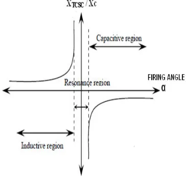
The relationship between firing angle ( ) and the TCSC reactance is a unique valued function therefore TCSC is modeled as a variable capacitive reactance. The TCSC is used in capacitive zone (21-23) .Fig. 2 shows the variation of XTCSC / Xc as a function of firing angle( ).
There is a value of the firing angle which causes steady state resonance. The device can be controlled in the capacitive or inductive zone, avoiding steady state resonance. For the inductive region, which is not used in steady state, acceptable values of the firing angle are
between 900 and maxL, where maxL < Res, with the
resonant value of the firing angle being determined by the ratio Xc/ XL.The capacitive region is limited by 1800 and
minC.TCSC allows the fundamental capacitive reactance to
be smoothly controlled over a wide range. The TCSC controller can be designed to control the power flow, to increase the transfer limits or to improve the transient stability (24-26). The TCSC controller can provide a very fast action to increase the synchronization power through quick changing of the equivalent capacitive reactance to the full compensation in the first few cycles after a fault, hence subsequent oscillations are damped. TCSC controller provides variable impedance, which is required for the compensation.
Fig. 2 XTCSC / Xc Vs FIRING ANGLE ( )CURVE
[image:2.612.349.531.396.574.2]© 2010, IJARCS All Rights Reserved 439 and the voltage drop becomes higher, the contribution of
series compensation increases and therefore system voltage will be regulated as desired.
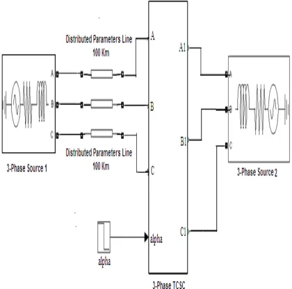
III. ENERGY SYSTEM DESIGN
[image:3.612.68.278.166.374.2]Considering a energy system as shown in the Fig.3 having two 3- Phase Sources connected with a 100 Km Transmission line.
Fig. 3 Power System connected with Series Controller
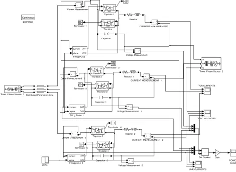
A 3-Phase series controller (TCSC) is placed in one of the parallel lines. The detailed MATLAB model developed of above system is shown in Fig. 4.
IV. MATLAB SIMULATION
The energy system shown in Fig. 4 is studied through the
computer simulation using the MATLAB/Simulink
software.
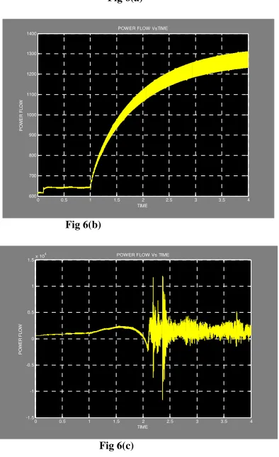
Fig.5 (a)-5(c), Fig.6 (a)-6(c) shows the TCSC reactance and Power flow when the TCSC firing is started at t = 0.1 sec., firing pulse generator is synchronized to current as the current has lesser harmonics. A 90 degree shift is then given so that it becomes synchronized with the capacitor voltage. The firing angle is varied from 160 to 150 degrees [Fig 5(a), Fig.6 (a)]. The firing angle is further varied from 1500 to
1400 [Fig 5(b), Fig.6 (b)] and1400 to 1300 [Fig 5(c),
Fig.6(c)].
It has been observed from Fig. 5 (a) that a variation of
firing angle from 1600 to 1500 leads to an increase in TCSC
reactance and thus increases power flow [Fig 6(a)]. This
shows the power flow control capabilities of TCSC.
From Fig 5(b) a further reduction of delay angle
from1500 to 1400 at one second causes an increase in
effective capacitive reactance but with decrease in power flow [Fig 6(b)]. This is due to the fact that for the firing
angle between 1500 to 1400 TCSC reactance may reaches in
Resonance region (Fig.2) which causes large value of TCSC reactance.
From Fig.5 (c) a further reduction of delay angle from
1400 to 1300 causes further increase in the TCSC reactance
Figure. 4 Matlab /Simulink model
Fig 5(a)
Fig 5(b)
[image:4.612.73.277.445.719.2]Fig 5(c )
Fig. 5 TCSC Reactance Vs Time when Firing Angle is varied from (a) 1600
to 1500
(b) 1500
to 1400
(c) 1400
to 1300
Firing pulse 2
Terminator 2
Terminator 4
powergui Continuous
alpha Voltage Measurement 2
v +
-Voltage Measurement 1
v + -Voltage Measurement v + -Thyristor 5 g m a k Thyristor 4 g m a k Thyristor 3 g m a k Thyristor 2 g m a k Thyristor 1 g m a k Thyristor g m a k
Three -Phase Source 2
A B C
Three -Phase Source 1
A B C Terminator 5 Terminator 3 Terminator 1 TCSC VOLTAGES TCR CURRENTS
Reactor 2 Reactor 1
Reactor LINE CURRENTS Gain K -current alpha Out1 Out2
Firing Pulse 1
current alpha Out1 Out2 Firing Pulse current alpha Out1 Out2 Dot Product Distributed Parameters Line
Current Measurement 2
i +
-Current Measurement 1
i + -Current Measurement i + -Capacitor 1
Capacitor 2 Capacitor
CURRENT MEASUREMENT 2
i +
-CURRENT MEASUREMENT 1
i + -CURRENT MEASUREMENT i + -POWER FLOW
0 0.5 1 1.5 2 2.5 3 3.5 4
10 11 12 13 14 15 16 17 TIME T C S C R E A C T A N C E
TCSC REACTANCE Vs TIME
0 0.5 1 1.5 2 2.5 3 3.5 4
10 20 30 40 50 60 70 80 90 100 TIME T C S C R E A C T A N C E
TCSC REACTANCE Vs TIME
0 0.5 1 1.5 2 2.5 3 3.5 4
-1 0 1 2 3 4 5 6x 10
5 TIME T C S C R E A C T A N C E
TCSC REACTANCE Vs TIME
615 620 625 630 635 640 645 P O W E R F L O W
[image:4.612.325.538.613.742.2]© 2010, IJARCS All Rights Reserved 441
Fig 6(a)
Fig 6(b)
Fig 6(c)
Fig. 6 Power Flow Vs Time when Firing Angle is
varied from (a) 1600
to 1500
(b) 1500
to 1400
(c) 1400
to 1300
V. CONCLUSION
The above MATLAB simulation results shows that for power flow enhancement through the existing transmission lines, TCSC controller is an effective technique. The reactance of the TCSC controller is a function of its thyristor firing angle. It has been shown through simulations that the device has to be controlled either in the capacitive or inductive zone and avoiding resonance region.
VI. REFERENCES
[1] N.G.Hingorani and L Gyugyi. Understanding FlexibleAC Transmission System concepts and technology of Flexible AC transmission systems. IEEE Press, NewYork.
[2] Varma Rajiv k, “Elements of FACTS controllers “,IEEE Transmission & Distribution Conference & Exposition,pp.1-6,2010. [3] Brian.K.Johnson, “How FACTS Controllers Function In an AC
Transmission System”, IEEE Power Engineering Review 2003. [4] Patel R. N., Improvement of power system
transient stability by coordinated operation of fast valving and breaking resistor, doctoral diss.,I.I.T. Delhi, India, Nov. [5] L. Angquist, “Dynamic Performance of TCSC Schemes”, CIGRE. [6] P.kundur.Power system stability and control. McGraw-Hill, New
York etc, 1994
[7] Wang, Y.Zhu, W, Mohler, R.R.Spee, R.,”Variable-struture control of flexible AC transmission systems”.IEEE Proc.of 31st
Conference on Decision and Control.1992, Vol.4, pp.3544-3549.
[8] K.R.Padiyar, K.Uma Rao,”Discrete control of TCSC for stability improvement in power systems,”IEEE on control Applications, 1995. [9] S.H Kim, J.U.Lim, and S.Moon, “Enhancement of Power System
Security Level through the Power Control of UPFC,’ IEEE Con, pp. 38-43, 2000.
[10] Abido,M.A,“Pole placement technique for PSS and TCSC based stabilizer design using simulated annealing, “Electrical power & energy Systems, Vol.20, 1998.
[11] K.R.Padiyar, Power System Dynamics Stability and Control, BS Publications, 2nd Edition, Hyderabad, India, 2002.
[12] G.Radman, R.S.Raje, “Dynamic model for power systems with multiple FACTS Controller,” Electrical Power system Research vol.78, issue 3, Pages361-371, 2008.
[13] Niclo,G.,Ceresoli,B.,Pincella,C.,Marukulam,Bortoni,G.,Presesti,P.,Go mez,r.,:Systems Studies for possibleapplications of facts devices on the enel transmission network”, Athens Power Tech. APT93, Proceeding on joint International Power Conferences Vol.1, pp.507-513.
[14] Wang, H.F, “Phillips-Heffron model of power systems installed with STATCOM and applications” Generation,Transmissionand Distribution IEEE ProceedingsVolume146, Issue 5, Pages: 521-527, 1999
[15] IEEE std 1159-1995 on Power Quality “IEEE Recommended Practice for Monitoring Electric Power Quality”. [16] Lei X., Li X., Povh D., A nonlinear control for
coordinating TCSC and generator excitation to enhance the transient stability of long transmission systems, Electric Power Research, 2001, Vol. 59, pp. 103 - 109.
[17] Zhang B. M., Ding Q. F., The development of FACTS and its control, APSCOM – 97, Hong Kong, Nov.1997, pp 48 – 53.
[18] R.M.Mathur and R.K.Varma.Thyristor-based Flexible AC Transmission System controllers for electrical transmission systems. IEEE Press, Piscataway, 2002.
[19] Y.H.Song Flexible AC Transmission System.The Institution of Electrical Engineers, London, 1999.
[20] Wang, H.F,“Modeling multiple FACTS devices into multi-machine power systems and applications” Electrical power & Energy systems, vol.25, pp.227-237, 2003.
[21] D.Shen and P.W.Lehn, “Modeling, Analysis, and Control of a Current Source inverter-based STATCOM”IEEE Transactions on Power Delivery, Vol.17, No.1, pp.248- 253, 2002
[22] A.M.Kulkarni, K.R.Padiyar, “Damping of power swings using series facts controllers,” Electrical Power and Energy systems, vol.21, pp. 475-495, 1999.
[23] N.Tambey, M.L.Kothari, “Damping of power system oscillations with UPFC,”IEE Proc.Trans. Distrib.Vol. 150, March 2003.
[24] S.H Kim, J.U.Lim, and S.Moon, “Enhancement of Power System Security Level through the Power Control of UPFC,’ IEEE Con, pp. 38-43, 2000.
[25] K.K.Sen, “Static Synchronous Series Compensator: Theory, Modeling and Application,” IEEE Trans on Power Delivery, 13 (1), pp. 241-246, 1998.
[26] N.Tambey, M.L.Kothari, “UPFC based Damping Controllers for Damping Low Frequency oscillations in a Power System,” IEE Proc. Trans. Distrib. Vol. 84, June 2003.
[27] M. A. Abido, “Analysis and assessment of STATCOM-based damping stabilizers for power system stability enhancement”, Electrical Power system Research vol.73, pp. 177-185, 2005. [28] B.Friedland, Advanmced Control System Design,Englewood Cliffs
,NJ;Prentice-Hall.
[29] N.Mimithulananthan, C.A.canizares, J.Reeve and G.J.Rogers, “Comparison of PSS, SVC, and STATCOM Controllers for Damping Power system Oscillations,” IEEE Transactions on Power Systems, Vol.18, No. 2, May 2003,pp. 786-792
[30] Yao Zhang ,Lili Dong ,Zhiqiang Goa,”Load frequency control for Multiple-Area Power Systems”, 2009 American control conference Hyatt Regency Riverfront , St. Louis ,MO, USA June 10-12,2009.
0 0.5 1 1.5 2 2.5 3 3.5 4
600 700 800 900 1000 1100 1200 1300 1400
TIME
P
O
W
E
R
F
L
O
W
POWER FLOW VsTIME
0 0.5 1 1.5 2 2.5 3 3.5 4
-1.5 -1 -0.5 0 0.5 1 1.5x 10
4
TIME
P
O
W
E
R
F
L
O
W
[image:5.612.77.274.57.380.2]