364
Finite Element Analysis of Stepped Bar using Matlab
and Ansys
Dhiraj. W. Ghatole
1, Pragati Rathi
2, Santosh Bhagyawant
3, Patil Ganesh
4Department of Mechanical Engineering 1,2,3,4, Sanmati College of Engineering College, Washim
[email protected] 1,[email protected]2,[email protected] [email protected] 4
Abstract-Through the numerical analysis technique called the finite element method, the deflection of stepped bars or beams can be accurately determined. This method is sensitive to the effect of the stress concentration. stepped bar is involved in many engineering application. These stepped bar systems suffer from the occurrence of deflection and stresses due to axial loading. These stresses and deflections have been examined to avoid possible resulting failure. This paper explains the application of finite element method for the analysis of a stepped bar subjected to an axial load. The element configurations that are studied range from one dimensional to three dimensional type and various mesh configurations. The Finite Element analysis results are compared with exact analytical solution and numerical solution of the stepped bar and this shows the elemental behavior of the stepped bar. . The methods employed in this study were analytical equations and finite element analysis. MATLAB® was used to transform analytical equations into graphs and at the same time to verify the finite element simulation of ANSYS®
Index Terms- Finite Element Analysis (FEA), Finite Element Method(FEM), Numerical Method (NM),Stepped Bar, ANSYS
1. INTRODUCTION
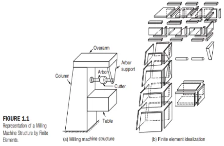
The basic idea in the finite element method is to find the solution of a complicated problem by replacing it by a simpler one. Since the actual problem is replaced by a simpler one in finding the solution, we will be able to find only an approximate solution rather than the exact solution. The existing mathematical tools will not be sufficient to find the exact solution (and sometimes, even an approximate solution) of most of the practical problems. Thus, in the absence of any other convenient method to find even the approximate solution of a given problem, we have to prefer the finite element method. Moreover, in the finite element method, it will often be possible to improve or refine the approximate solution by spending more computational effort. In the finite element method, the solution region is considered as built up of many small, interconnected subregions called finite elements. As an example of how a finite element model might be used to represent a complex geometrical shape, consider the milling machine structure shown in Figure 1.1(a). Since it is very difficult to find the exact response (like stresses and displacements) of the machine under any specified cutting (loading) condition, this structure is approximated as composed of several pieces as shown in Figure 1.1(b) in the finite element method. In each piece or element, a convenient approximate solution is assumed and the conditions of overall equilibrium of the structure are derived. The satisfaction of these conditions will yield an approximate solution for the displacements and stresses
Figure 1:Representation of a Milling Machine Structure by Finite Element
365 pressure or velocity distribution if it is a fluid
mechanics problem. In eigenvalue problems also, time will not appear explicitly. They may be considered as extensions of equilibrium problems in which critical values of certain parameters are to be determined in addition to the corresponding steady-state configurations. In these problems, we need to find the natural frequencies or buckling loads and mode shapes if it is a solid mechanics or structures problem, stability of laminar flows if it is a fluid mechanics problem, and resonance characteristics if it is an electrical circuit problem. The propagation or transient problems are time-dependent problems. This type of problem arises, for example, whenever we are analysis of stepped bar using FEM and MATLAB and found result obtained by FEM and MATLAB were matched. ANSYS 11.0 Workbench result for the same problem was also close to the values obtained with an error of just around 1% which was acceptable.
MATLAB is extensively used for scientific & research purposes, so GulabPamnaniat. at al.[5] has carried out Beam analysis in MATLAB. It is accurate & also has a number of built in functions which makes it versatile and they conclude that MATLAB is a quick and efficient way of analyzing the beam design and also can be use to solve beam design problems faster and errorless.
ANSYS Workbench software is a very useful tool in a various kinds of constructional elements or set if those elements design for analysis and demonstrates by L. A. Dobrzanski at. al.[6] .Via this software, problems connected with material deformation as well as distribution of stresses occurring in it can be analyzed. Finite Element Method (FEM) is a numerical technique for finding approximate solutions to boundary value problems for partial differential equations. It is also referred to as finite element analysis (FEA). FEM subdivides a large problem into smaller, simpler, parts, called finite elements [2].
Cantilever beam of different materials and dimensions is considered for the dynamic analysis of free vibration at no load condition as well as comparison between materials by Rishi Raj at.al.[7]. The modelling, simulation and analysis of cantilever beam is done by using ANSYS & MATLAB and theoretically by finite element method (FEM) for the evaluation of natural frequency and mode shape. By using Lagrange’s equation, the formulation of
equation motion for the beam is derived, through which stiffness and mass matrix is obtained.
3. TOOLS FOR ANALYTICAL SOLUTION
FOR STEPPED BAR
3.1 Introduction to MATLAB
MATLAB integrates mathematicalcomputing, visualization, and a powerful language to provide a flexible environment for technical computing. The open architecture makes it easy to use MATLAB and its companion products to explore data, create algorithms, and create custom tools that provide early insights and competitive advantages.
Mat lab (Matrix laboratory) is an interactive software system for numerical computations and graphics. As the name suggests, Mat lab is especially designed for matrix computations: solving systems of linear equations, computing Eigen values and eigenvectors, factoring matrices, and so forth. In addition, it has a (computer-aided engineering, or CAE) developer that is headquartered south of Pittsburgh in Canonsburg, Pennsylvania, United States. ANSYS offers a comprehensive range of engineering simulation solution sets providing access to virtually any field of engineering simulation that a design process requires. The tools in ANSYS put a virtual product through a rigorous testing procedure such as crashing a car into a brick wall before it becomes a physical object. The ANSYS Workbench platform is the framework upon which the industry’s broadest and deepest suite of advanced engineering simulation technology is built. With bi-directional CAD connectivity, powerful highly-automated meshing, a project-level update mechanism, pervasive parameter management and integrated optimization tools, the ANSYS Workbench platform delivers unprecedented productivity, enabling Simulation Driven Product Development.
4. Procedure to Solve Analytical Solution of Stepped Bar
4.1
Define Problem
Define Problem
366 stepped bar shown in fig below. Predict the nodal
displacement at U2 & U3.
A1 = 2400 mm2, A2 = 1200 mm2, A3 = 600 mm2. L1 = 800 mm, L2 = 600 mm, L3 = 400 mm.
E1 = 83 × 103 MPa, E2 = 10 × 103 MPa, E3 = 200 × 103
Mpa
Figure. No.2 – Stepped bar.
4.2 . Analytical Solution
The force is applied on the stepped bar as shown in figure due to that the displacement or deformation of the nodes are occurs. These deformation can be calculated byusing the following analytical formula,
Where,
P = Axial force in N. l = Length of the step in mm.
A = Cross sectional area of bar in mm2. E = Modulus of elasticity in N/mm2. C. Solution
1. Displacement of node 2
Displacement of node 3
Node 1 & Node 4 are fixed so there is no any displacement
i.e. dl1 = dl4 =
5. RESULT & DISCUSSION
Problem no. 01
Three concentric rings of different materials are joined together as shown in fig. 6.1. Determine the displacement at the free end.
Figure. No.3 – Concentrated Ringd.
Solution: This physical system can be represented by a finite element model as shown in fig 6.2. There are 3 elements in this case, but each is represented by the same nodes.
Figure No.4 : Nodes The element connectivity table is as shown:
Find the displacement and element stresses for the given Figure No.5
Fig.ure No.5: Composite Stepped Bar Table : 6.3 : Properties of Elements
Steel Aluminium Brass
Area (mm2)
400 350 350
367
Solution-Formation of element stiffness matrix K1=(A1×E1)÷L1=
Formation of global force matrix-
[F]=[
Assembly of global stiffness nodal displacement- [K]×{ }={ }
Apply boundary conditions- u1=0 and u4=0
Erase first and fourth row and first and fourth column.
[ boundary conditions. The results obtained from MATLAB and solving the problem using FEM were nearly same but result obtained by ANSYS workbench are very close to the value obtained by FEM and MATLAB which is acceptable.
This process of solving the problems would result in saving a lot of time, and avoiding common errors that usually occur in manual calculations. However, writing MATLAB codes for solving higher order equations is difficult..
REFERENCES
[1] GopichandAllaka, Manikanta Kati, B. Srikanth, SkRashed& D Neehaar, (March -April 2013), “Modal Analysis Of A Stepped Bar Using Matlab&Ansys”, International Journal of Engineering Research and Applications (IJERA) ISSN: 2248-9622, Vol. 3, Issue 2, pp. 504-509. [2] Tirupathi R. Chandrupatla, “Introduction to Finite
Elements in Engineering”, 3rd edition, pp. 1-50. [3] MATLAB Guide to Finite Elements. An
Interactive Approach, by Peter I. Kattan, pp. 11-44, 109-136.
[4] Engineering programming in MATLAB: A Primer, by Mark A. Austin, Institute for System Research, University of Maryland, College Park, Maryland 20742, U.S.A. (February, 2000), pp. 41-64. [5] GulabPamnani, Dageshwar Singh Rajput, Nikhil
368 Point Load & UDL)”, Advance Physics Letter,
ISSN:2349-1108, Vol. 1, Issue 2, pp. 27-36. [6] L. A. Dobrzanski, A. Pusz, A. J. Nowak, M.
Gorniak,(Sep.-Oct. 2010), “Application of FEM for solving various issues in material engineering”, JAMME, Journal of Achievements in Materials and Manufacturing Engineering, Vol. 42, Issues 1-2, pp. 134-141.