2366
Static and Harmonic Analysis of Truck Chassis with
Tuned Mass Damper under Class-B Road Conditions
Mahendra varma.M1, Lakshmana kishore.T2
P.G student, Mechanical Engineering1, Assistant Professor, Department of Mechanical Engineering2
1,2
JNTUK University College of Engineering, Vizianagaram-535003, Andhra Pradesh, India Email: [email protected]1, [email protected]2
Abstract-Chassis is major vital component in a vehicle structure. The main theme of this project involves static structural and harmonic analysis to investigate the key characteristics of a truck chassis .The static response includes identification of failure zone location and high stress concentration area and also determines the deformation of the truck chassis. Finite element analysis (FEA) is used to determine the dynamic response parameters of truck chassis such as the natural frequencies and mode shapes. Numerical analysis was done to validate with the FEA models. Design modification of the chassis model was done by placing tune mass damper to optimize the vibrations of the truck chassis and to reduce the chances of failure. The main area which is to be analyzed in the existing truck chassis model was the structural resonance at 53 Hz, experienced during the combine bending and torsion modes. Modifications of existing design of chassis to shift natural frequencies were proposed by placing tune mass damper which is a combination of spring mass damper system which carrying 3% of mass of the entire chassis mass in order to reduce the amplitude in turn to increase the frequency which leads to reduce the effect of vibration of chassis under good road conditions.
Index Terms-Heavy Truck Chassis, Tuned Mass Damper, Inertia Loads
1. INTRODUCTION
Vehicle truck Chassis frame is a key noted element which acts as base for all components like Body, Engine, Transmission system, Axles, wheels, Suspension system. The chassis frame acts as housing for components which are placed on it which are responsible for impact loads from the suspension and gravitational loads.
The truck chassis frame has two side rails and several cross beams of different thickness. The side rails are designed as C type beams; however crossed beams are attached to side rails by braces with bolts and nuts. The chassis mainly classified according to type of frames
• Laddered frame chassis
• Space frame chassis
• Backbone chassis
• Tube design chassis
• Monocoque chassis
In India, two types of trucks which are used in the market those are mining trucks and normal market purpose trucks are used different type of operations.
2.PROBLEM IDENTIFICATION
When vehicle moving on the road, the vehicle truck chassis frame is subjects to the dynamic forces which are induced by the Bumps, Potholes, Roughness of the road and the impact loads which are due to suspension effect from the road irregularities. The vehicle truck chassis leads to vibrate in such various dynamic excitations. If any of the excitation frequencies value occurs simultaneously match with the natural
Frequencies value of the mining truck vehicle chassis, so resonance events occurs and the chassis will undergo unwanted huge Oscillations that may leads to deflection and Failure. In this analysis, the factor that affects the heavy truck chassis is necessary to minimize these problems. Chassis failure is related to several factors such as the poor quality of roads on which vehicles are driven, vehicle speed, etc. Then, stress analysis is done to identify the dynamic nature and displacements of the chassis which is important to determine the failure zone and the location having the highest stress due to random vibrations that were considered as the critical location which may responsible for failure of chassis
3. OBJECTIVE OF THE WORK
3.1. Static analysis
• To determine Von Misses stresses
• To determine Maximum principal stresses
• To determine Normal and Shear stresses
• To determine maximum deflection
3.2. Modal analysis
• Modal analysis was done to know the mode shapes of the vehicle truck chassis for the class of first six natural frequencies and also deformation of chassis
• In order to obtain the resonance and frequency for the chassis by plotting the amplitude vs. frequency graph
3.4. Simulation of road profile
• To analyze displacement profile, stress and deformation of chassis frame
vehicle truck chassis frame moving on the
• Material properties: The selected material properties are taken from ansys library material considered as structural steel.
• Meshing: meshing operation is done in ANSYS for geometry which is imported from CATIAV5 where the entire geometry is divided in to small elements.
• Boundary conditions: The loads are applied on the side rails of the chassis and supports were given according to the position.
• Solve: the solution is obtained from t given conditions as input in ANSYS such as static structural, dynamic analysis and harmonic response.
• Post processing: the results taken for analysis.
5 .CHASSIS AND SUSPENSION MODEL The heavy vehicle truck chassis TATA LPT truck taken and those specifications are shown in the followings tables.
Table-1Material properties of heavy vehicle frame 6 Ground clearance 7 Capacity(GVW)
Table-2 Specifications of heavy vehicle chassis frame Material amplitude vs. frequency graph.
displacement profile, stress and deformation of chassis frame when the properties are taken from ansys library. The
structural steel. Meshing: meshing operation is done in
which is imported from CATIAV5 where the entire geometry is divided in to small elements.
ons: The loads are applied on the side rails of the chassis and supports were given according to the position. Solve: the solution is obtained from the given conditions as input in ANSYS such as static structural, dynamic analysis and
Post processing: the results taken for
CHASSIS AND SUSPENSION MODEL The heavy vehicle truck chassis TATA LPT 3718tc
of heavy vehicle chassis frame
5.1. Calculation for chassis frame:
Truck Model =TATA LPT 3718 Max Capacity of Truck
=37 ton (Kerb Weight+ Payload) =37000kg =37000*10= 370000N Truck with capacity of 1.25%
=370000*1.25N =462500N Total load concentrating on the chassis =462500N
The parts of chassis are made of ‘C’ channels with 285mm*65mm*7mm. Truck chassis having two beams. So the load impinging on each side rail of the total load impinging on the chassis
Load impinging on the each frame = (total load impinging on the chassis/2)
= (462500/2) =231250N/Beam
5.2. Loading calculations:
Continuous Beam with uniformly distributed load chosen for this analysis. Load impinging
span of beam 231250 N. Length of the Beam is 9760 mm.
Uniformly Distributed Load is 231250/9760 =23.69N/mm.
418 842 317 1582 2872 2633 1182
Fig.1.Total load acting on the beam
6. STATIC MODEL:
In this, geometrical modeling of chassis and its various components has been carried out
V5 software. Each and every dimensions of chassis
on the chassis frame
‘C’ channels with 285mm*65mm*7mm. Truck chassis having two on each side rail is half on the chassis frame. on the each frame = (total load
= (462500/2) =231250N/Beam
Beam with uniformly distributed load is impinging on the full span of beam 231250 N. Length of the Beam is 9760
Uniformly Distributed Load is 231250/9760
2872 2633 1182
Total load acting on the beam
this, geometrical modeling of chassis and its various components has been carried out in CATIA V5 software. Each and every dimensions of chassis frame taken from reference (Tata LPT 3718tc
7. MESHEDMODEL:
The method used for meshing is tetrahedrons and finer meshing is applied at certain portion. The number Nodes is 161878 and number of elements is 8807 This will approaches result outcome precise and possible.
Fig.3. Meshed model of chassis frame
8. LOAD DISTRIBUTION
The load which is impinging on the chassis frame is considered as uniform distributed load which is obtained from total load divided by throughout length of the chassis frame. The total load impacted
area of chassis frame is 231250N/beam. Total boundary conditions which are front two and last two cross member are fixed and force on side rail beam of chassis considered as 23.69N/mm.
Fig.4.Load distribution of chassis frame
The method used for meshing is tetrahedrons and finer meshing is applied at certain portion. The number of is 161878 and number of elements is 88070. This will approaches result outcome precise and
nging on the chassis frame is considered as uniform distributed load which is by throughout length The total load impacted on upper beam. Total six front two and last two force on side rail beam of
oad distribution of chassis frame
9. STRESS
The result of study shows that maximum von miss stress on entire vehicle truck chassis frame is shown in below figure, which is at rear of the chassis frame and near the rear wheel axle.
Fig.5.Stress distribution of chassis
10. DEFORMATION OF CHASSIS
The result of this study shows that deformation of vehicle truck chassis frame is 1.39mm which is shown in below figure and also critical location was identified.
Fig.6.Displacement pattern in terms of maximum weight load
The result of study shows that maximum von miss stress on entire vehicle truck chassis frame is shown in at rear of the chassis frame and
Stress distribution of chassis
DEFORMATION OF CHASSIS:
The result of this study shows that deformation of vehicle truck chassis frame is 1.39mm which is shown in below figure and also critical location was
11. MODAL ANALYSIS:
The modal analysis is the basic technique used for analysis of dynamic character. Mode shapes and natural frequencies were examined through this approach. The key characteristics of
the structure can be figured out through this analysis and the actual vibration response under this frequency range can be predicted. The outcome
analysis considered as reference input value for harmonic analysis.
In this paper Modal analysis is performed on vehicle truck chassis and the natural Frequencies been found out, the first eight natural frequencies listed in the following Table 3.
Mode No Frequency(Hz) Deformation
1 53.001 0.003316
2 66.947 0.0074191
3 106.76 0.015422
4 119.08 0.0086682
5 121.41 0.00929
6 129.04 0.0080685
7 133.74 0.003636
8 146.33 0.0081813
Table-3Shows that the deformation of chassis at Natural frequencies
12. MODE SHAPES
Fig.7.Mode1-natural frequency53.001 Hz
is the basic technique used for Mode shapes and natural frequencies were examined through this characteristics of every mode of d out through this analysis response under this frequency outcome of modal analysis considered as reference input value for
Modal analysis is performed on the Frequencies have natural frequencies are
Deformation(mm)
0.003316
0.0074191
0.015422
0.0086682
0.00929
0.0080685
0.003636 0.0081813
the deformation of chassis at
natural frequency53.001 Hz
Fig.8. Mode2-Natural frequency 66.947Hz
Fig.9.Mode3-Natural frequency 106.976Hz
Fig.10.Mode 4-natural frequency
Natural frequency 66.947Hz
Natural frequency 106.976Hz
13. DESIGN MODIFICATION OF CHASSIS:
Fig.11.Design modification of chassis
Tuned mass damper is combination of spring and damper system. From the modal analysis
that at the frequency 53 Hz chassis ampli very high so it is essential to reduce the ampli we need to introduce tuned mass damper at that particular frequency mode the amplit
decreases which was shown fig.10.
14. TUNED MASS DAMPER:
Tune mass damper is a vibration absorber system which is widely used for controlling unwanted vibration in mechanical engineering system. scenario TMD theory and its principle adopted to minimize vibrations of structure. mass damper device is a combination of mass, damping and spring is effective and stable structural vibration control device generally attached to primary vibration system for suppressing unwanted
When the basic structure is subject external disturbances the fundamental
basic structure resonance with the natural frequency of the TMD is tuned. So that huge amount of
energy is transmitted to TMD and then dissipated the damping. Tuned mass damper is
primary structure and its natural frequency is tuned to be very near to the dominant mode of
structure, considerable reduction in the dyna responses of primary structures. A number of approaches are available currently which can be used for control vibration. Broadly classified as active, passive and hybrid methodologies, each
its advantages and inherent drawbacks. One of these control measures is the TMD - the tuned mass
DESIGN MODIFICATION OF CHASSIS:
Design modification of chassis
is combination of spring and rom the modal analysis we observed frequency 53 Hz chassis amplitude was essential to reduce the amplitude so we need to introduce tuned mass damper at that ular frequency mode the amplitude value
Tune mass damper is a vibration absorber system which is widely used for controlling unwanted vibration in mechanical engineering system. Present theory and its principle have been vibrations of structure. Tuned mass damper device is a combination of mass, damping and spring is effective and stable structural vibration control device generally attached to primary vibration system for suppressing unwanted vibrations. structure is subjects to unwanted fundamental mode of the with the natural frequency of that huge amount of vibrating energy is transmitted to TMD and then dissipated by is placed on a and its natural frequency is tuned to to the dominant mode of the primary
which effectively attenuates the vibration energy at resonance.
14.1. Tuned mass damper design
Mass of Chassis Mb=850 Kg
Mass of Tune Mass Damper Mt= (3to 5%) Of Mass of Beam
Mt=0.03 X 850
Finally Mass Of Tune Mass Damper Is 25.5kg. Tuned Frequency Is 53 Hz.
=
Therefore Final K= 2824953 N/m. Mass ratio µ= =0.03.
15.1. Frequency Vs amplitude graph
In order to get vibration response at different l of the chassis harmonic analysis is carried out. Harmonic analysis is done in the frequency range of 0Hz to 200Hz at solution intervals of 200 vibration at different location is measured in terms of frequency and amplitude.
Fig.12. frequency @ 53Hz Vs Ampli
15.2. Frequency Vs amplitude graph (modified chassis)
From harmonic analysis of existing chassis the amplitude value is very high which is obtained at 53Hz frequency. Design modification chassis by placing tune mass damper, the amplitude response was decreased which is shown in below Fig.
s the vibration energy at
Tune Mass Damper Mt= (3to 5%) Of Mass of
Finally Mass Of Tune Mass Damper Is 25.5kg.
order to get vibration response at different location armonic analysis is carried out.
existing chassis the tude value is very high which is obtained at esign modification chassis by tude response was
Fig.13. Frequency @53Hz Vs Ampli
16. LOADS DUE TO ROADS PROFILE:
The excessive vibrations of chassis and suspension occur as the vehicle experiencing through
profiles
A Two degree freedom suspension Quarter
model is effectively used to study the dynamic response between vehicle and road roughness The equations for 2DOF vehicle model are derived from the Newton’s 2ndlaw of motion. In
mass (Ms) and it is attached to unsprung mass (Mus free to move vertically with respect to the sprung mass. The tire is modeled as spring of stiffness (Kus and dampers of damping coefficients (Cu suspensions between the sprung mass and
sprung masses are modeled as linear spring of stiffness (Ks) respectively, and linear damper with damping equations governing the motion of the sprung and un sprung masses against excitations cause
roughness (h) as follows
Sprung mass: equations are simulated in the Simulink of MATLAB software using different blocks. The Simulink environment is used to modelling, simulating and
Amplitude
LOADS DUE TO ROADS PROFILE:
and suspension ing through uneven road
Quarter vehicle to study the dynamic road roughness profile. vehicle model are derived law of motion. In which sprung sprung mass (Mus) vertically with respect to the sprung eled as spring of stiffness (Kus) pers of damping coefficients (Cu) the suspensions between the sprung mass and the
un-s linear un-spring of un-stiffneun-sun-s per with damping equations governing the motion of the sprung and un-sprung masses against excitations caused by the road equations are simulated in the Simulink of MATLAB software using different blocks. The Simulink , simulating and
analysis of dynamic systems and supports non linear and linear systems. In this environment, we able to simulate and execute a system by blocks and use the results for different purposes. The output of the above system is the vertical acceleration of sprung mass, which can be used to obtain the dynamic force.
Fig.14. Quarter vehicle model
The boundary conditions are applied to the position of the connection between the spring elements and chassis. Also, the unsprung mass of the truck has been distributed on the plates, between the spring elements. In addition, the displacement of the truck in the directions of the axial and the lateral axis at the mentioned boundaries should be constra
the spring of the vehicle truck is linear. Also, because the truck does not rotate around the perpendicular axis of its body (yaw), the truck rotation, the motion of the longitudinal and lateral directions should be constrained. Now, by considering the mentioned boundaries, road roughness, considered as random load, can be applied to the truck.
17.PARAMETERS VALUES OF 2DOF SYSTEMS
Table-4vehicle parameters for 2DOF suspension model
Parameter Symbol
Description
MS
Sprung mass of the vehicle body
Stiffness of the tire
Cs use the results for different purposes. The output of the above system is the vertical acceleration of sprung sed to obtain the dynamic force.
Quarter vehicle model
The boundary conditions are applied to the position of elements and the chassis. Also, the unsprung mass of the truck has been distributed on the plates, between the spring elements. In addition, the displacement of the truck in the directions of the axial and the lateral axis at the mentioned boundaries should be constrained because truck is linear. Also, because the truck does not rotate around the perpendicular axis of its body (yaw), the truck rotation, the motion of the longitudinal and lateral directions should be ering the mentioned boundaries, road roughness, considered as random
PARAMETERS VALUES OF 2DOF SYSTEMS
2372 A random road of class-B is developed in time bound
with parameters listed in the below table using
MATLAB/SIMULINK
SNO Parameter
Random Road Profile Of Type-B
(ISO-8606)
1 Variance 4*10-3
2 Velocity(m/s) 60
3
α (Depends on type of road surface)
0.127
Table-5 Parameters of Random profile road CLASSB
18. SIMULATION OF DIFFERENT ROAD CLASSES
Table-6 Parameters of Random profile road CLASSB
Fig.15.Simulation of quarter vehicle model in the SIMULINK environment of MATLAB software
19. RESULTS AND DISCUSSION
19.1. Static analysis
S NO
Parameter Theoretical
FEM Analysis
1 DEFORMATION (mm)
1.69 1.39
2 MAX STRESS (Mpa)
340 330
Table-7 The maximum stress on the chassis and deformation
19.2.Harmonic analysis
Fig.16. Frequency Vs amplitude graph for chassis with Tuned mass damper and chassis without Tuned
mass damper
In harmonic frequency response analysis of chassis without and with TMD is shown in Fig.15, for the input is given in the frequency range 0-200 Hz. The response was computed at frequencies observed as peak values obtained.
From the graph, we observed that frequency vs. amplitude positions of chassis with tune mass damper and chassis without tune mass damper. from harmonic analysis we were creating artificial frequency range from 0 – 200 Hz. in that range truck chassis has highest amplitude value at 53 Hz so we need minimize that frequency by placing tune mass damper setup at that particular frequency, after placing TMD, amplitude value decreased this shows that our chassis is safe. Then there is a reduction in amplitude of considerable percentage at resonance condition due to installation of Tuned Mass Damper.
-5.00E-02 0.00E+00 5.00E-02 1.00E-01 1.50E-01 2.00E-01
0 50 100 150
without
with Road
class
@ ABCDE Roughnes
s Variance
FGBABCDED,
= A
Power spectral density
I JKL /E
Class B(good
4 4 0.12
20. DYNAMIC ANALYSIS
Dynamic analysis is used to determine von misses’ stress and displacement profile of chassis with respect to time factor.
20.1. Stress and deformation
Fig.17. The location of critical stress of chassis in CLASS-B road
Dynamic force obtained by the quarter vehicle model used to simulate uneven road in CLASS
condition. In this case force is applied at front axle then with time (l/v) where l is distance between two axles, v is the speed of the vehicle.
In this case maximum stress and deformation generated on the chassis in ISO road CLA
470 Mpa and 20.22mm. The location of critical stress and the zones of failure were identified.
Fig.18.The Displacement of chassis under road profile
is used to determine von stress and displacement profile of chassis
The location of critical stress of chassis in
Dynamic force obtained by the quarter vehicle model used to simulate uneven road in CLASS –B road n this case force is applied at front axle and then with time (l/v) where l is distance between two
In this case maximum stress and deformation generated on the chassis in ISO road CLASS –B was he location of critical stress and the zones of failure were identified.
of chassis under CLASS B
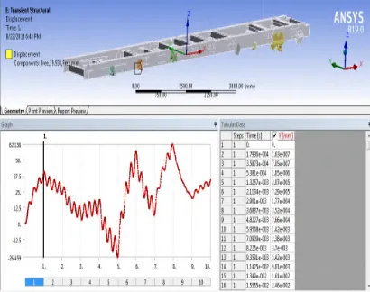
20.2. Displacement profile
The displacement profile of chassis under class b road condition which is shown in below figure
Fig.19. Displacement profile of chassis frame in CLASS-B road
21. CONCLUSION
The study aim is to analysis a heavy vehicle chassis structure using numerical method of FEM. this regard, different elements of the chassis and weld connections are modeled in CATIA and then entered into ANSYS software and were meshed. Afterwards, static and dynamic forces such as weight force and forces caused by road roughness were examined and applied to the model. Road roughness was also simulated based on the ISO 8606and the dynamic forces applied to the chassis frame were extracted using simulation of a quarter-vehicle model during a motion of constant speed and by introducing tune mass damper the amplitude of chassis decreases with Considerable limit in turn to reduce
effects and the displacement of chassis observed.
REFERENCES
[1].P.L. Menezes, Kishore, S.V. Kailas, M.R. Lovell, Role of surface texture, roughness, and hardness on friction during unidirectional sliding, Tribol. Lett. 41(2011) 1–15.
[2]. I. Etsion, State of the art in laser surface texturing, J. Tribol.-Trans. ASME 127 (2005) 248–253.
[3].Y. Liu, T. Waters, M. Brennan, A comparison of semi-active damping control strategies for vibration isolation of harmonicdistur Journal of Sound and Vibration 280 (2005) 21 [4].Mohamed M. ElMadany&Zuhair, S. Abduljabbar,
“Linear Quadratic Gaussian Control of a Quarter The displacement profile of chassis under class b road
figure
Displacement profile of chassis frame in
The study aim is to analysis a heavy vehicle truck chassis structure using numerical method of FEM. In of the chassis and weld ons are modeled in CATIA and then entered into ANSYS software and were meshed. Afterwards, static and dynamic forces such as weight force and forces caused by road roughness were examined and applied to the model. Road roughness was also the ISO 8606and the dynamic forces applied to the chassis frame were extracted vehicle model during a motion of constant speed and by introducing tune mass damper the amplitude of chassis decreases with turn to reduce the vibration and the displacement of chassis profile were
[1].P.L. Menezes, Kishore, S.V. Kailas, M.R. Lovell, Role of surface texture, roughness, and hardness on friction during unidirectional sliding, Tribol.
[2]. I. Etsion, State of the art in laser surface Trans. ASME 127 (2005)
Quarter-2374 Car Suspension”, Aug, 2010, Vehicle System
Dynamics, 32:6, 479-497
[5].G.Verros& Papadimitriou, Design optimization of Quarter-car Models with Passive and Semi-active Suspensions under Random Excitation, Journal of Vibration and Control, January 2005, 11:581-606.
[6].D. Karnopp, M.J. Crosby, System for controlling the transmission of energy between spaced members, United States Patent, 1974.
[7].Hongyi Li, Honghai Liu1, Chris Hilton and Steve HandNon-fragile H-infinity control for half-vehicle active suspension systems with actuator uncertainties”, Journal of Vibration and Control,2012, 19(4) 560-574.