Volume 11, Special Issue I, May 2020
International Journal of Advanced Research in Computer Science
CONFERENCE PAPER
Available Online at www.ijarcs.info
2nd International Conference on
Advances in Computing & Information Technology (IACIT-2020) Date: 29-30 April 2020
Organized by School of Computing and Information Technology Reva University, Bengaluru, India
ISSN No. 0976-5697
SMART BLIND STICK PRO
Taraniya.I1,Bhaskar Reddy P.V2,Varshini Chaithra3,Yeddula Divyasri4,Nalam Lakshmi Raviteja5 [1],[3],[4],[5] III B.Tech,School of Computing and Information Technology, REVA University,Bengaluru.
[2]
Professor, School of Computing and Information Technology, REVA University,Bengaluru. [email protected], [email protected], [email protected],
[email protected], [email protected]
Abstract-Planet consists of several people one of whom is visually disabled people. Currently, the World Health Organization estimates that 76 million visually disabled individuals are still alive in the world. As a normal human being able to leave his or her life alone, however visually disabled people are dependent on him or her to fulfil the basic needs. This society becomes increasingly evolving, a range of new technologies have been developed that enable blind people to sustain their lives without being dependent but it still has its pitfalls. So we are suggesting a workaround in this to introduce a highly innovative and inexpensive smart blind stick to the visually disabled.In this paper we use ultrasonic sensors for detecting obstacles, global positioning systems (GPS) and global system for mobile communication (GSM) modules for tracking positions and sends a message to the configured number. The thermistor that helps sense the ambient heat temperature and IR sensor to identify the potholes when driving, The individual buzzer is accomplished to get acquainted with the unit. When a person heads towards an obstacle, the buzzer resounds. The main point of view of this program is to guide the visually impaired to their service.
Keywords— Arduino Uno micro-controller, ultrasonic sensor, infrared sensor, GPS module, GSM module, thermistor, buzzer.
I. INTRODUCTION
Blindness is a condition that cannot be seen due to injury, illness, or congenital condition. Globally, 285 million people with visual disabilities are trying to lead their lives in this country. These people feel uncomfortable during the maneuver. Visually disabled people are taking external assistance to complete their routines or move around.[12] Safety is more important to every living being. Health is a big factor when it comes to a blind person. There are many existing devices, such as smart blind caps, smart blind shoes, smart blind cloves.voice base navigation system using ultrasonic sensors[7].There are many smart canes along with android smartphone assistance to aid the blind person[6]. Each of these has its drawbacks. Compared to all of these designs, a smart blind walking stick could be more reliable and self-reliant to a visually impaired person. Keeping all of these in mind, we designed a smart blind stick pro. This system is fitted with sensors, GPS and GSM units[1], a thermistor, a buzzer, and a microcontroller. It guides a person to identify an obstacle[10], a pothole, and a fire on his or her path. It keeps track of their location and sends the message back to the specified number. Sensors can be used to record information about the existence of
obstacles in a route. Such kinds of active sensors can track and sense obstacles from far and close.in this case Ultrasonic sensors is used. This therefore defines a exact estimate of the distance between the blind and the
obstruction. In the field of obstacle detection.four different types of active sensors may be used: infrared,laser, ultrasonic, in addition to radar sensors. Ultrasonic sensor is
used to detect the obstacles. It measures the distance between the object and the stick.RF transmitter and receiver are added to recognize the stick when it is far from the client [1]..potholes on their way using an ultrasonic sensor. LDR sensor is used to sense the light intensity of the surroundings and LED is illuminated correspondingly. The moisture sensor is used to spot the moisture in the environment. Usage of an ultrasonic tracker to detect the
potholes. The light intensity of the surroundings is measured by the LDR sensor and the LED is illuminated
2nd International Conference on that the GPS receiver is useful for knowing the subject's
current position and nearby landmarks. Some solutions are already on the market such as: UltraCanne, Isonic, Teletact and others. These devices aid people who are blind by gathering information from sensors and then communicating feedback by vibration or sound to the consumer. They cannot sense obstructions that are obscured but very dangerous to the blind, such as ramps, pits, etc. As a result, instruction is required to help the user identify the signals and to respond to them in real-time. Through our research, we have sought to overcome some of the disadvantages:
We have built stick to sense obstacles and to be able to recognize and alert them.
The preparation of our company is not as costly as the preparation of other products. Our instruction is just a definition of the stick part and the usage position.
II. LITERATURE SURVEY
Various groundbreaking tools have been developed around the world to find a way for people with visual disabilities. During the construction of a visually handicapped navigation system, the primary emphasis was on obstacle identification, staircase identification, water detection, potholes detection and location monitoring, etc.
A)Smart assistance navigation system for visually impaired individuals[1]:
This proposed paper elucidates how the device helps the blind person to detect the obstacle. Ultrasonic sensor is used to detect the obstacles. It measures the distance between the object and the stick. Buzzer is used to caution the insight person. RF transmitter and receiver are added to recognize the stick when it is far from the client. GPS and GSM module is used to provide an alert message to his/her guardian in case of any emergency[1].
Disadvantages:
i. No detection of potholes.
ii. Surrounding temperature or fire on his/her way is not notified.
iii. One ultrasonic sensor is used.
B)Smart Cane for Assisting Visually Impaired People[2]:
This paper relies on developing a maneuver system that guides an inside person to detect any hurdles and potholes on their way using an ultrasonic sensor. LDR sensor is used to sense the light intensity of the surroundings and LED is illuminated correspondingly[2]. The moisture sensor is used to spot the moisture I the environment and GSM is added to send the message in an emergency to the number which is configured to the system.
Disadvantage:
i. No temperature sensor is used to detect the surrounding temperature.
ii. Buzzer is not used to alert the person.
C)Navigation gadget for visually impaired[3]:
This paper reveals the nature of the headset navigation devices to help them find their way through the city, enabling the inner person to navigate by voice control to reach their destination[3]. Path obstacle detection is conducted using an ultrasonic sensor calibrated to the microcontroller. Using Bluetooth, the phone and the stick are connected in this GPS device..
Disadvantages:
i. No detection of temperature and potholes are made.
ii. Comparatively expensive.
D)Smart cane for visually impaired based on IOT[4]:
This paper explores the detection of fire, the detection of obstacles. Besides this, the pit holes and the stairs are also found. This is achieved by the use of an infrared camera. For this device, the GPS and GSM modules are completed to monitor the position of the insight user. Both of these electronic devices are operated and done with raspberry pi[4]. This cane is fitted with a warning, too.
III. COMPONENTS
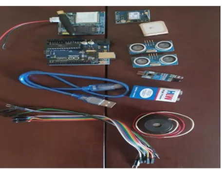
Fig.1 shows the images of all the components used in this prototype.
Hardware:
Ultrasonic sensor
Infrared sensor
Thermistor
Buzzer
Arduino Uno
GPS module
GSM module
Fiber stick
Battery
Jumper wires Software:
[image:2.612.322.550.492.665.2] Arduino IDE
Taraniya.Iet al, International Journal of Advanced Research in Computer Science, Vol 11, Special Issue I, May 2020,224-228
2nd International Conference on
Advances in Computing & Information Technology (IACIT-2020) Date: 29-30 April 2020
Organized by School of Computing and Information Technology Reva University, Bengaluru, India
226 IV. METHODOLOGY
A) Ultrasonic Sensor
Ultrasonic sensor measures distance by using ultrasonic waves. The transmitter of the ultrasonic sensor sends the ultrasonic waves, these waves reflect to the receiver when it detects the obstacle. It measures the distance to the target by measuring the time between the emission and reception.
Fig 2: HC-SR04 Ultrasonic sensor
B) Infrared sensor
[image:3.612.330.521.114.241.2]It is an electronic sensor that measures infrared (IR) light radiating from the object in the field of view.
Fig 3: Infrared sensor
C) Arduino Uno
It is a microcontroller board, contains an on-board power supply, USB port to communicate with PC, and Atmel microcontroller chip. It simplifies the process of creating any control system by providing the standard board that can help the programmed and connected to the system without the need for any sophisticated PCB design and implementation.It is an open-source
[image:3.612.84.234.155.244.2]hardware..
Fig 4: Arduino uno micro-controller
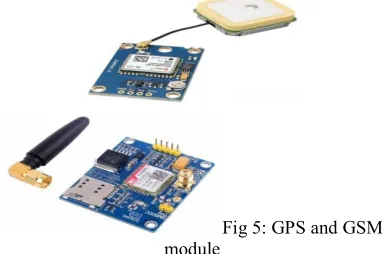
D) GPS and GSM module:
The GPS module obtains location information from satellites in the form of latitude and longitude[6]. This information is processed by the microcontroller and sent to the GSM module. The GSM module sends a message to the number configured[8].
Fig 5: GPS and GSM module
E) LM35 Thermistors
It is one kind of commonly used temperature sensor that can be used to measure temperature with an electrical output comparative to the temperature in degree celsius.
Fig 6: LM35 thermistor with pin configuration
F) Buzzer
[image:3.612.371.479.309.398.2]Buzzer is an audio signally device. It beeps when sensors detect any obstacle.
Fig 7: Buzzer
V. IMPLEMENTATION
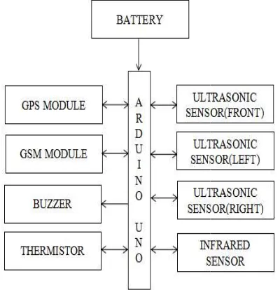
[image:3.612.77.308.541.658.2]found, the message is sent to the Arduino Uno microcontroller, where it runs the code and then sends a message to the user through the buzzer beeping 3 times, cautioning that there is an obstacle in the path of the visually impaired. The thermistor sensor is mounted below to the front ultrasonic sensor of the blind stick to measure the ambient temperature of the visually disabled individuals. This takes a single step where it senses only the barrier that happens in front of the insight person, as soon as it senses the heat and sends a signal to the visually disabled person by beeping the buzzer for 1 time. The IR sensor is mounted to the bottom of the stick to locate the potholes that appear on the path of the visually disabled person. The buzzer beeps twice when he/she is headed with a pothole. Here comes the most critical aspect of our proposed paper where the Neo 6m GPS module is used along with the sim 900A GSM module with the introduction of the sim c
[image:4.612.325.538.138.436.2]module monitors the position of the blind stick users and then sends the position message to the number that is already configured to the blind stick, this process takes place through the microcontroller where the reliable code is used. All these individual components are accomplished with the Arduino Uno microcontroller where the code is executed. Every element is coded to execute the expected operation.
Fig 8: Block diagram of the proposed prototype
VI. FLOWCHART
The proposed system being applied in this documentation is explained briefly in the flowchart displayed in Fig 9.[1] This system operates on four separate algorithms, i.e. used with an ultrasonic sensor to detect obstacles. If the interval is less than 400 cm the buzzer beeps three times. An infrared sensor is used to locate potholes during the operation. Buzzer beeps twice as the distance between the pothole and the blind stick is more than 15 cm. Thermistor is used to alert a human whether he or she is heading for a fire on his
2nd International Conference on
found, the message is sent to the Arduino Uno microcontroller, where it runs the code and then sends a message to the user through the buzzer beeping 3 times, path of the visually impaired. The thermistor sensor is mounted below to the front ultrasonic sensor of the blind stick to measure the ambient temperature of the visually disabled individuals. This takes a single step where it senses only the barrier that happens in front of the insight person, as soon as it senses the heat and sends a signal to the visually disabled person by beeping the buzzer for 1 time. The IR sensor is mounted to the bottom of the stick to locate the potholes that appear on f the visually disabled person. The buzzer beeps twice when he/she is headed with a pothole. Here comes the most critical aspect of our proposed paper where the Neo 6m GPS module is used along with the sim 900A GSM module with the introduction of the sim card, the GPS module monitors the position of the blind stick users and then sends the position message to the number that is already configured to the blind stick, this process takes place through the microcontroller where the reliable code is used. ese individual components are accomplished with the Arduino Uno microcontroller where the code is executed. Every element is coded to execute the expected operation.
Fig 8: Block diagram of the proposed prototype
The proposed system being applied in this documentation is explained briefly in the flowchart displayed in Fig 9.[1] This system operates on four separate algorithms, i.e. used with an ultrasonic sensor to detect obstacles. If the interval is less cm the buzzer beeps three times. An infrared sensor is used to locate potholes during the operation. Buzzer beeps twice as the distance between the pothole and the blind stick is more than 15 cm. Thermistor is used to ading for a fire on his
[image:4.612.91.291.328.535.2]or her way. The buzzer beeps once when the temperature is higher than 60 degrees Celsius. An individual can send a message to his / her guardian using the GSM module. If the location is not seen, it goes back to the position logging. Thus, with all such instructions, a visually impaired person can function safely.
Fig 9: flowchart of the proposed prototype
VII.RESULT
This proposed prototype is designed using different electronic devices which are ultrasonic sensor, infrared sensor, thermistor, GPS and GSM module, buzzer. All these are configured with the Arduino Uno microcontroller to detect the obstacle, potholes, fire. In addition to all these GPS and GSM modules is used to track the location and send the message to the configured number with the stick.
VIII.CONCLUSION
From the review of all the reference paper and works, this proposed prototype comes with an extra feature i.e., LM35 thermistor. Different sensors are used to detect obstacles and potholes. To detect any fir
the insight person LM35 thermistor is used. Moreover, only one buzzer is used with different times of beeping, so that a person can identify whether it is an obstacle, a pothole or a fire. GPS and GSM module is used to track or her way. The buzzer beeps once when the temperature is higher than 60 degrees Celsius. An individual can send a message to his / her guardian using the GSM module. If the location is not seen, it . Thus, with all such instructions, a visually impaired person can function
Fig 9: flowchart of the proposed prototype
This proposed prototype is designed using different electronic devices which are ultrasonic sensor, infrared sensor, thermistor, GPS and GSM module, buzzer. All these are configured with the Arduino Uno microcontroller to detect the obstacle, potholes, fire. In addition to all these GPS and GSM modules is used to track the location and send the message to the
VIII.CONCLUSION
Taraniya.Iet al, International Journal of Advanced Research in Computer Science, Vol 11, Special Issue I, May 2020,224-228
2nd International Conference on
Advances in Computing & Information Technology (IACIT-2020) Date: 29-30 April 2020
Organized by School of Computing and Information Technology Reva University, Bengaluru, India
228
the location and send the message to the predefined number.
IX.FUTURE IMPROVEMENT
In the proposed model only ultrasonic sensor, infrared sensor, GPS and GSM panel, thermistor and buzzer are included in the model. There is no room for the identification of any dust, stairway identification, etc. It can use the vibrators instead of the buzzer to warn the user. Could install only a couple more sensors including a temperature sensor to sense moisture in the air, a gas sensor.
X.ACKNOWLEDGEMENT
We would like to express our gratitude to Dr. Bhaskar Reddy P.V. Professor, Department of Computer Science, Reva University for his strong guidance ongoing supervision and encouragement during this course of study research which will enable us to achieve the planned target amid a maze of possibilities and failures.
XI.REFERENCES
[1].Mrs.S.Divya, shubhamRaj, M.praveen shai,”Smart assistance Navigation system for visually impaired individuals”,IEEE International Conference on Intelligent Techniques and Control,Optimization and signal processing,volume-2,issue-2019,pp. 978-1-5386-9543 [2].Nandini AV,Aniket Dwivdi,Nilita Anil kumar,”Smart cane for assiting visually impaired people”, IEEE Region 10 Conference (TENCON )-volume-6,issue-2019,pp. 978-1-7281-1895-6.
[3].Sankari subbaih, S ramya, G parvathy Krishna, Senthic nayagam,”Smart cane for visually impaired based on IOT”, 3rd International Conference on Computing and Communication Technologies (ICCCT) 2019, pp.978-1-5386-9371.
[4].Varalakshmi,S kumarakrishnan, ”Navigation system for visually challenged using internet of things”, IEEE International Conference on Computation, Automation and Networking (ICSCAN)-volume-5,issue-2019,spp.978-1-7281-1524.
[5].K.S.K. Lokesh, A, T Manjunath, "Electronic stick along with android smartphone's to the aid of blindly disabled individuals", International Journal of Recent Trends in Engineering & Research, vol. 2, no. 5, 2016.
[6].Gita Indah Hapsari , Giva Andriana Mutiara , Dicky Tiara Kusumah,“Smarts cane location for blind using GPS”, 5th IEEE International Conference on Information and
Communication Technology (ICoICT) conference ,2017,pp. 978-1-5090-4911.
[7].Anushree Harsur, M Chitra, "Voice Based Navigation System For Blind People Using Ultrasonic Sensor", International Journal on Recent And Innovation Trends in Computing and Communication(IJRITCC), vol. 3, no. 6, pp.4117-4122, 2015
[8].M Naveen Kumar, K. Usha, "Voice Based Guidance and Location Indication System for The Blind Using GSM GPS and Opical Device Indicator", International Journal of Engineering Trends and Technology (IJETT), vol. 4, no. 7, 2013.
[9].A. Harsur, M. Chitra, "Voice Based Navigation System for Blind People Using Ultrasonic Sensor",International Journal on Recent And Innovation Trends in Computing and Communication(IJRITCC), vol. 3, pp. 4117-4122, 2017.
[10].Swagat Das, Sonal patro ,Ritika Das,”Arduino based safety device for visually challenged”,IEEE International Conference on Communication and Signal Processing 2019, pp. 978-1-5386-7595.
[11].Amesh sen kaustav, Sen Jyothi Das,”Ultrasonic blind stick for completely blind people to avoid any kind of obstacle”,IEEE International Conference On Computer Science, Electrinoc and Networking (ICSENS) 27-dec-2018. ,pp. 978-1-5386-4707.