ISSN(Online): 2319 - 8753
ISSN (Print) :2347 - 6710
I
nternational
J
ournal of
I
nnovative
R
esearch in
S
cience,
E
ngineering and
T
echnology
(An ISO 3297: 2007 Certified Organization)
Vol. 4, Issue 1, January 2015
Modeling and Simulation of Solar PV Module
on MATLAB/Simulink
Ami Shukla
1*, Manju Khare
2, K N Shukla
3PG Student, Department of Electrical &Electronics, Lakshmi Narain College of Technology, Bhopal, India1 Associate Professor, Department of Electrical &Electronics, Lakshmi Narain College of Technology, Bhopal, India2
Research Scholar, Department of Energy, Maulana Azad National Institute of Technology Bhopal, India3 *Corresponding author
ABSTRACT:This work focuses on a program developed in MATLAB/Simulink of 36W photovoltaic module. This program is based on mathematical equations and is described through an equivalent circuit including a photocurrent source, a diode, a series resistor and a shunt resistor. The developed program allows the prediction of PV module behavior under different physical and environmental parameters. This program can also be used to extract the physical parameters for a given solar PV module as a function of temperature and solar radiation. Effect of two environmental parameters of temperature and irradiance variations could be observed from simulated characteristics. The program simulation results are compared with the datasheet information and they found to have good agreement.
KEYWORDS: Solar energy, photovoltaic, PV module, characteristics, programming, performance.
I. INTRODUCTION
Solar energy has the greatest potential of all the sources of renewable energy. If only a small amount of this form of energy could be used, it will be one of the most important supplies of energy specially when other sources in the country have depleted energy comes to the earth from the sun. This energy keeps the temperature of the earth above than in colder space, causes current in the atmosphere and in ocean. It causes the water cycle and generates photosynthesis in plants. The solar power where sun hits atmosphere is 1017 W. The solar power on the surface of earth is 1016W. The total worldwide power demand of all needs of civilization is 1013W. Therefore, the sun gives us 1000 times more power than we need. If we can use 5% of this energy, it will be 50 times what the world will require [1]. Electrical energy that can be produced from the solar energy by photovoltaic solar cells. SPV cell converts the solar energy directly to electrical energy. The most significant applications of SPV cells in India are the energization of pump sets for irrigation, drinking water supply and rural electrification covering street lights, community TV sets, medical refrigerators and other small power loads. Sunshine available in India is for nearly 300 days in a year [2].
Solar Energy has been used by mankind since long. Earlier however the use was restricted to utilization of Solar Energy for basic drying or heating purposes. It was soon realized that Solar Energy can be put to better use by utilization of sophisticated system for Water heating used at domestic level, or Industrial level, drying etc. The use of Solar Energy for electrical power generation dates back to Space age when Solar Photo Voltaic cells were used to power Satellites orbiting around the Earth. With passing time it was realized that Solar Photo Voltaic can be used as a Power source not just for satellites but as also the cleanest and greenest power source on Earth. Solar Energy thus started being used not just for conventional purposes such as heating but also power generation [2].
ISSN(Online): 2319 - 8753
ISSN (Print) :2347 - 6710
I
nternational
J
ournal of
I
nnovative
R
esearch in
S
cience,
E
ngineering and
T
echnology
(An ISO 3297: 2007 Certified Organization)
Vol. 4, Issue 1, January 2015
Solar energy is a very important resource but is still largely underutilized in India. It currently accounts for only about 0.8% of the total power generation capacity in India. On an average the country has 300 sunny days a year and received an annual radiation of 1600-2200 kWh/m2 translating into an annual estimated potential of 6 billion GWh. To tap this vast potential of solar energy the MNRE has launched an initiative, solar radiation resources assessment (SRRA) which aims to developed solar atlas by assessing and quantifying the availability of solar radiation across country [3-4].
The amount of solar energy produced in India in 2007 was less than 1% of the total energy demand. The grid-connected solar power as of December 2010 was merely 10 MW. Government-funded solar energy in India only accounted for approximately 6.4 MW-yr of power as of 2005. However, India is ranked number one in terms of solar energy production per watt installed, with an insolation of 1,700 to 1,900 kilowatt hours per kilowatt peak (kWh/KWp). 25.1 MW was added in 2010 and 468.3 MW in 2011. By January 2014 the installed grid connected solar power had increased to 2,208.36 MW, and India expects to install an additional 10,000 MW by 2017, and a total of 20,000 MW by 2022 [3].
With about 300 clear, sunny days in a year, India's theoretical solar power reception, on only its land area, is about 5000 Petawatt-hours per year (PWh/yr) (i.e. 5,000 trillion kWh/yr or about 600,000 GW) [2,3]. The daily average solar energy incident over India varies from 4 to 7 kWh/m2 with about 1,500–2,000 sunshine hours per year (depending upon location), which is far more than current total energy consumption. For example, assuming the efficiency of PV modules were as low as 10%, this would still be a thousand times greater than the domestic electricity demand projected for 2015 [3].
Solar powered electrical generation relies on photovoltaic system and heat engines. Solar energy's uses are limited only by human creativity. To harvest the solar energy, the most common way is to use photo voltaic panels which will receive photon energy from sun and convert to electrical energy. Solar technologies are broadly classified as either passive solar or active solar depending on the way they detain, convert and distribute solar energy. Active solar techniques include the use of PV panels and solar thermal collectors to strap up the energy. Passive solar techniques include orienting a building to the Sun, selecting materials with favorable thermal mass or light dispersing properties and design spaces that naturally circulate air. Solar energy has a vast area of application such as electricity generation for distribution, heating water, lightening building, crop drying etc.
In PV power generation, due to the high cost of modules, optimal utilization of the available solar energy has to be ensured. Also PV system requires special design considerations due to the varying nature of the solar power resulting from unpredictable and sudden changes in weather conditions, which change the radiation level as well as the cell operating temperature. This mandates an accurate and reliable simulation of designed PV system prior to installation [5, 6]. Solar photovoltaic systems performance depends on several environmental parameters like solar insolation, temperature, wind speed and shading. The performance of such system requires a precise knowledge of the I-V and P-V characteristics curve.
II. RELATED WORK
ISSN(Online): 2319 - 8753
ISSN (Print) :2347 - 6710
I
nternational
J
ournal of
I
nnovative
R
esearch in
S
cience,
E
ngineering and
T
echnology
(An ISO 3297: 2007 Certified Organization)
Vol. 4, Issue 1, January 2015
nonlinear I-V equation by adjusting the curve at three operating conditions: open circuit, maximum power, and short circuit points [11]. Bhatt and Thakker (2011) studied electrical characteristics of PV Array have been obtained as a function of temperature [12].Alsayid and Jallad (2011) a matlab/simulink/PSIM based simulation of PV cell, PV module and PV array has been carried out and compared with 50W solar panel [13].Mohammed (2011) have carried out matlab/simulink based modeling of modules with the output power of 60W and 64W have been attempted [14].Richhariya and Pachori (2011) have designed a user friendly solar cell model with irradiance and cell temperature as input parameters, by using matlab/simulink and have verified it with a commercial module [15]. Ramos-Hernanz et. al. (2012) have compared two PV Simulation Models in time domain by using matlab/simulink, to achieve an I-V curve similar to the manufacturer‟s data sheet. However, these models have been developed with a large number of assumptions, some of which are even practically unrealistic [16]. Bikaneria et.al (2013) have studied in this paper one diode photovoltaic cell model are focused. Simulation studies are carried out with different temperature [17]. Venkateswarlu and Raju (2013) the study of photovoltaic systems in an efficient manner requires a precise knowledge of the IV and PV characteristic curves of photovoltaic modules. A Simulation model for simulation of a single solar cell and two solar cells in series has been developed using sim electronics (matlab/simulink) environment and is presented here in this paper. A solar cell block is available in sim electronics, which was used with many other blocks to plot I-V and P-V characteristics under variations of parameters considering one parameter variation at a time. Effect of two environmental parameters of temperature and irradiance variations could also be observed from simulated characteristics [18]. Vajpai and Khyani (2013) presents the development of a matlab/simulink model for the solar PV cell, module and array. The simulation of photovoltaic module for obtaining the performance characteristics has also been carried out in this paper. The developed model is then simulated and validated experimentally using PSS1237 solar panel. The experimental results obtained, exhibited a good agreement with the simulated data [19]. Bonkoungou et al. (2013) this paper presents a photovoltaic (PV) cell to module simulation model using the single-diode five parameter models. The model was implemented in matlab software and the results have been compared with the data sheet values and characteristics of the PV module in Standard Test Conditions (STC). Parameters values were extracted using Newton Raphson‟s method from experimental Current (I)-Voltage (V) characteristics of Solar ex MSX60 module. The results obtained are in good agreement with the experimental data provided by manufacturer. The approach can thus, be very useful for researchers or engineers to quickly and easily determine the performance of any photovoltaic module [20].
In this paper, performance characteristics of 36W (Tata BP 184459) PV module under varying module temperature and varying solar irradiance level is analyzed by a single-diode equivalent circuit model in matlab/simulink script. The proposed modeling method avoid complexities involve in PV parameters identification while achieving comparable accuracy.
III. GENERAL DESCRIPTION OF A PHOTOVOLTAIC CELL
ISSN(Online): 2319 - 8753
ISSN (Print) :2347 - 6710
I
nternational
J
ournal of
I
nnovative
R
esearch in
S
cience,
E
ngineering and
T
echnology
(An ISO 3297: 2007 Certified Organization)
Vol. 4, Issue 1, January 2015
Figure 1. Concept of photovoltaic [21]
Crystalline and polycrystalline silicon‟s are the materials most commonly used in photovoltaic cells. The advantage of silicon cells is primarily the abundance of silicon on earth. The photovoltaic cell consists of several layers of semiconductor materials with different electronic properties [35]-[38]. In a typical polycrystalline cell, the bulk of the material is silicon, doped with a small quantity of boron to give it a positive or p-type character. A thin layer on the front of the cell is doped with phosphorous to give it a negative or n-type character. The interface between these two layers produces an electric field and forms the so-called a “cell junction” [39]. When the cell is exposed to sunlight, a certain percentage of the incoming photons are absorbed in the region of the junction, freeing electrons in the silicon crystal. If the photons have enough energy, the electrons will be able to overcome the electric field at the junction and are free to move through the silicon and into an external circuit. The direction of the electric current is opposite to its direction if the device operates as a diode. The next section dwelled on the modeling of photovoltaic system.
A photovoltaic array (PV system) is a interconnection of modules which in turn is made up of many PV cells in series or parallel. The power produced by a single module is not enough for commercial use, so modules are connected to form array to supply the load.
Figure 2: Solar PV Cell, Module and Array
Most PV arrays use an inverter to convert the DC power into alternating current that can power the motors, loads, lights etc. The modules in a PV array are usually first connected in series to obtain the desired voltages; the individual modules are then connected in parallel to allow the system to produce more current [21].
IV. METHODOLOGY
MATHEMATICAL MODELING OF A PHOTOVOLTAIC MODULE:
ISSN(Online): 2319 - 8753
ISSN (Print) :2347 - 6710
I
nternational
J
ournal of
I
nnovative
R
esearch in
S
cience,
E
ngineering and
T
echnology
(An ISO 3297: 2007 Certified Organization)
Vol. 4, Issue 1, January 2015
connected in parallel with a light generated current source (IL) as shown in Figure 3.3, the equation for the output
current is given by:
PV cells are made of semiconductor materials, such as silicon. For solar cells, a thin semiconductor wafer is specially treated to form an electric field, positive on one side and negative on the other. When light energy strikes the solar cell, electrons are knocked loose from the atoms in the semiconductor material. If electrical conductors are attached to the positive and negative sides, forming an electrical circuit, the electrons can be captured in the form of an electric current - that is, electricity. This electricity can then be used to power a load.
The power produced by a single PV cell is not enough for general use. So by connecting many single PV cell in series (for high voltage requirement) and in parallel (for high current requirement) can get us the desired power. Generally a series connection is chosen this set of arrangement is known as a module. Generally commercial modules consist of 36 or 72 cells. The p-n junctions of mono-crystalline silicon cells may have adequate reverse current characteristics and these are not necessary. Reverse currents waste power and can also lead to overheating of shaded cells. Solar cells become less efficient at higher temperatures and installers try to provide good ventilation behind solar panels.
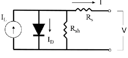
A solar cell is the building block of a solar panel. A photovoltaic module is formed by connecting many solar cells in series and parallel. Considering only a single solar cell; it can be modeled by utilizing a current source, a diode and two resistors. This model is known as a single diode model of solar cell. Two diode models are also available but only single diode model is considered here [24], [25], [26], [29], [30] and [31].
Figure 3: Single diode model of a solar cell
I-V Equation of PV cell:General mathematical description of I-V output characteristics for a PV cell has been studied for over the past four decades [24]. The PV cell is usually represented by the single diode model. The single diode equivalent circuit of a solar cell is shown in Figure 3.The I-V characteristics equation of solar cell [23] is given as follows:
I = IL- IO 𝑒𝑥𝑝 𝑞 (𝑉+𝐼𝑅𝑆 )
𝐴𝑘𝑇𝑐 − 1 – (𝑉+𝐼𝑅𝑆)
𝑅𝑆ℎ (1)
IL is a light generated current or photo current (representing the current source), IO is the saturation current
(representing the diode), Rs series resistance, A is diode ideality factor, k (= 1.38 ×10⁻²³ W/m2K) is Boltzmann‟s
constant, q (=1.6×10⁻¹⁹C) is the magnitude of charge on an electron and TC is working cell temperature.
Photo current or light generated current, mainly depends on the solar insolation and cell working temperature, which is described as:
IL = G [ISC + KI (TC –Tref)] (2)
Where Isc is the short circuit current at 25℃ and 1KW/m2, KI is the short circuit current temperature coefficient, Tref is
the reference temperature and G is the solar insolation KW/m2, on the other hand, the cells diode current or saturation current varies with the cell temperature which is described as:
IO = IRS 𝑇𝐶 𝑇𝑟𝑒𝑓
3
exp
𝑞𝐸𝐺 1 𝑇𝑟𝑒𝑓 −
1 𝑇𝐶
𝐾𝐴 (3)
Where IRS is the cells reveres saturation current at reference temperature and a solar radiation, EG is the band-gap
ISSN(Online): 2319 - 8753
ISSN (Print) :2347 - 6710
I
nternational
J
ournal of
I
nnovative
R
esearch in
S
cience,
E
ngineering and
T
echnology
(An ISO 3297: 2007 Certified Organization)
Vol. 4, Issue 1, January 2015
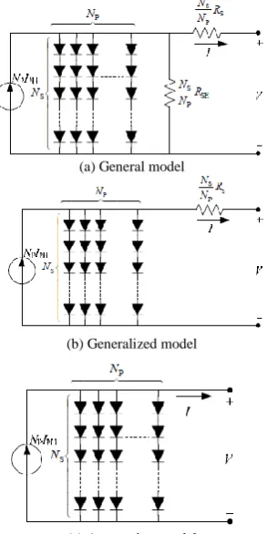
I-V equation of a PV module:I-V equation of a PV module is similar to that of solar cell, except that the module I-V curve is the combination of I-V curves of all solar cells connected in a module.
Equation 1 can be written in terms of voltage of a single solar cell as well V = - IRS + K log[
𝐼𝐿−𝐼+𝐼𝑂
𝐼𝑜 ] (4)
Where, K is a constant (=𝐴𝑘𝑇
𝑞 ).
If Imo and Vmo are the current and voltage of solar PV module, respectively than relationship between Imo and Vmo will
be similar to that of a solar cells I-V relationship, i.e Vmo = - Imo RSmo + Kmolog(
𝐼𝐿𝑚𝑜−𝐼𝑚𝑜+𝐼𝑂𝑚𝑜
𝐼𝑂𝑚𝑜 ) (5)
Where ILmo light generated current of module, IOmo is reverse saturation current of the module, Rsmo is the series
resistance of the module and Kmo is the constant for the module. If there are NS cells connected in series in a module,
than its series resistance will be the sum of each cells series resistance Rsmo = NS×RS. Similarly, the module constant
will be written as Kmo= NS×K. But since same current flows in series connected cells, the current terms in equation 5
will be the same as that of individual cell i.e Iomo= Io and ILmo= IL. Thus, the module Imo-Vmo equation of NS series
connected cells will be written as:
Vmo = - Imo NS RS +NS Klog(
𝐼𝐿−𝐼𝑚𝑜+𝐼𝑜
𝐼𝑜 ) (6)
In the similar fashion, the current–voltage equation can be written for the parallel connected cells. If there are NP cells
connected parallel in a module, than relationship between the current and voltage of the module will be given as: Vmo = -Imo
𝑅𝑠
𝑁𝑝 + 𝐾 log(
𝑁𝑠ℎ𝐼𝐿−𝐼𝑚𝑜+𝑁𝑝𝐼𝑜
𝑁𝑝𝐼𝑜 ) (7)
In the case of parallel connection the series resistance is divided by the number of cells in parallel (Np) and light
generated current and reverse saturation current get multiplied by the NP. In this case the module factor K remains
unaffected and is same as that of K of a single cell [22].
(a) General model
(b) Generalized model
(c) Appropriate model
ISSN(Online): 2319 - 8753
ISSN (Print) :2347 - 6710
I
nternational
J
ournal of
I
nnovative
R
esearch in
S
cience,
E
ngineering and
T
echnology
(An ISO 3297: 2007 Certified Organization)
Vol. 4, Issue 1, January 2015
V. PROGRAMMING BASED SIMULATION ON MATLAB/SIMULINK FOR SOLAR PV
MODULE
Simulation program is developed with considering single-diode PV cell mathmatical model with neglecting series and shunt resistances. Specific values of the input and climatic parameters are taken account at Bhopal location. Simulation program tested on matlab/simulink for 36 W Tata BP 184459 solar PV module at two conditions:
1. Constant solar radiation intensity and varying module temperature. 2. Constant temperature and varying solar radiation intensity.
Simulation parameters for above two conditions are listed in Table 1. and Table2
Table 1: Simulation Parameters for constant solar radiation intensity and varying module temperature.
Simulation Parameters Values
Solar radiation intensity (S) 800W/m2 (constant)
Temperature of cell (Tmod) 25ºC,35 ºC,40 ºC,45 ºC
Reference temperature (Tref) 40ºC
Short Circuit Temperature Coffecent (Ki) 0.00023mA/ºC
Reverse Saturation Current (Irr) 21×10-10 A
Boltzman‟s constant (k) 1.38×10⁻²³W/m2-K
Charge of electron (q) 1.602×10⁻¹⁹C
Cell Saturation Current (Iscr ) 0.75Ma
Fil Factor (FF) 0.85
Area of the Module (Ar) 0.40 m2
Ideality Factor (A) 4
The Curent Temperature Cofficient(α) 0.473mA/ºC
The Voltage Temperature Cofficient (β) 636 V/ºC
Band Gap Energy (Ego) 6.5eV
Number of Cells connected in parallel (Np) 4
Number of Cells connected in series (Ns) 9
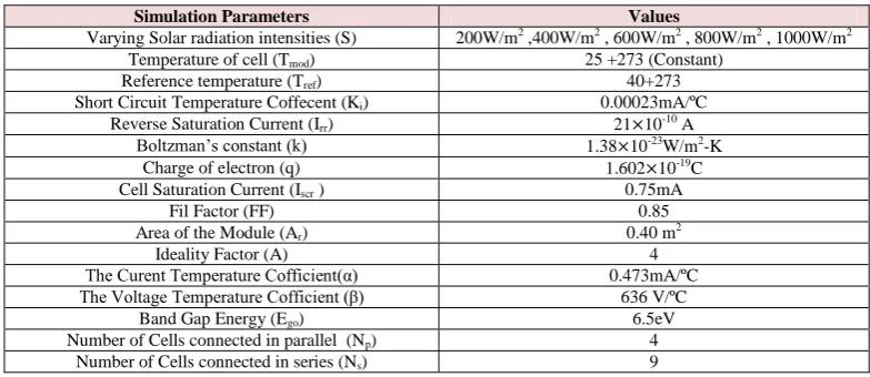
Table 2 : Simulation Parametersfor Constant temperature and varying solar radiation intensity.
Simulation Parameters Values
Varying Solar radiation intensities (S) 200W/m2 ,400W/m2 , 600W/m2 , 800W/m2 , 1000W/m2
Temperature of cell (Tmod) 25 +273 (Constant)
Reference temperature (Tref) 40+273
Short Circuit Temperature Coffecent (Ki) 0.00023mA/ºC
Reverse Saturation Current (Irr) 21×10-10 A
Boltzman‟s constant (k) 1.38×10⁻²³W/m2-K
Charge of electron (q) 1.602×10⁻¹⁹C
Cell Saturation Current (Iscr ) 0.75mA
Fil Factor (FF) 0.85
Area of the Module (Ar) 0.40 m2
Ideality Factor (A) 4
The Curent Temperature Cofficient(α) 0.473mA/ºC
The Voltage Temperature Cofficient (β) 636 V/ºC
Band Gap Energy (Ego) 6.5eV
Number of Cells connected in parallel (Np) 4
Number of Cells connected in series (Ns) 9
ISSN(Online): 2319 - 8753
ISSN (Print) :2347 - 6710
I
nternational
J
ournal of
I
nnovative
R
esearch in
S
cience,
E
ngineering and
T
echnology
(An ISO 3297: 2007 Certified Organization)
Vol. 4, Issue 1, January 2015
Table 3: Specification of the PV module
VI. RESULTS AND DISCUSSION
The most important points widely used for describing the modules electrical performance are: the shortcircuit point, where the current is at maximum (Short circuit current Isc ) and the voltage over the module is zero; the open circuit point, where the current is zero and the voltage is at maximum (Open circuit voltage Voc); the maximum power point , where the product of current and voltage has its maximum. The power delivered by a PV module attains a maximum value at the points (Imp,Vmp).
Typical three points (Isc,0),(Voc,0) and (Imp,Vmp) are provided by the manufacturer data sheet at standard test
condition (STC) . An accurate estimation of these points for other conditions is the main goal of every modeling technique .from the aforementioned models, it is obvious that the PV module acts as a current source near the short circuit point and as a voltage source in the vicinity of the open circuit point.
VARYING MODULE TEMPERATURE WITH CONSTANT IRRADIANCE:
Table 4. Simulated output parameters at varying temperature (25˚C, 30˚C, 35˚C, 40˚C, 45˚C) with constant solar irradiance (800W/m2).
Temperature (0C)
Voc
(V)
Isc
(A)
Vm
(V)
Im
(A)
Pm (W)
25 18.40 2.42 16.00 2.26 36.16
30 17.80 2.42 15.00 2.29 34.47
35 17.00 2.42 15.00 2.15 32.35
40 16.80 2.42 14.00 2.22 31.07
45 15.70 2.42 13.00 2.26 29.48
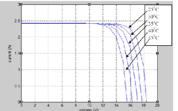
Fig 5, 6 and Table 4 shows the simulation results of I-V, P-V characteristics for the varying temperature from 250C to 450 C in 50C steps with constant solar irradiance 800W/m2. In this condition, short circuit current (Isc) is staying
almost constant. Similarly with increase in cell temperature the open circuit voltage (Voc) and maximum power output
of the P-V module both are decreases. The results thus confirm the non-linear nature of P-V module. The simulation results obtained are identical with the curves given by the manufacturer.
Figure 5 : I-V characteristics of 36W (Tata BP 184459) solar PV module with varying temperature and constant solar radiation intensity.
On the contrary the temperature increase around the solar cell has a negative impact on the power generation capability. Increase in temperature is accompanied by a decrease in the open circuit voltage value. Increase in
Model Tata BP 184459
Maximum power 36W
Open circuit voltage 18V
Short circuit current 2A
Number of cells 36
Dimensions 950×425×35 mm
Weight 6 kg
ISSN(Online): 2319 - 8753
ISSN (Print) :2347 - 6710
I
nternational
J
ournal of
I
nnovative
R
esearch in
S
cience,
E
ngineering and
T
echnology
(An ISO 3297: 2007 Certified Organization)
Vol. 4, Issue 1, January 2015
temperature causes increase in the band gap of the material and thus more energy is required to cross this barrier. Thus the efficiency of the solar cell is reduced [17].
Figure 6: P-V characteristics of 36W (Tata BP 184459) solar PV module with varying temperature and constant solar radiation intensity
VARYING IRRADIANCE WITH CONSTANT TEMPERATURE.
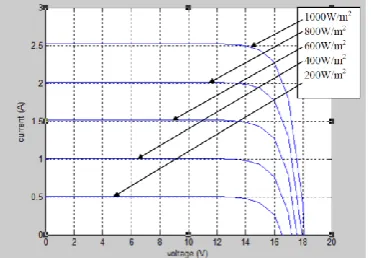
Table 5. Simulated output parameters at varying irradiance (1000W/m2, 800W/m2, 600W/m2, 400W/m2, 200W/m2) with constant module temperature (250C)
Irradiation Level(W/m2)
Voc
(V)
Isc
(A)
Vm
(V)
Im
(A)
Pm
(W)
200 16.50 0.50 14.00 0.47 6.65
400 17.00 1.01 15.00 0.93 13.85
600 17.60 1.51 15.00 1.42 21.42
800 17.90 2.01 15.00 1.93 28.99
1000 18.00 2.52 16.00 2.27 36.37
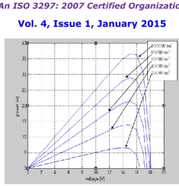
Fig 7, 8 and Table 5 shows the simulation results of I-V, P-V characteristics at the varying solar irradiance (200W/m2 to 1000W/m2) in 200W/m2 steps with constant module temperature (250C).The I-V and P-V curves of a solar cell are highly dependent on the solar irradiation values. It is very clear that current generated increases with increasing solar irradiance and maximum output power (Pm) also increases.
Figure 7: I-V characteristics of 36W (Tata BP 184459) solar PV module with varying solar radiation intensity and constant module temperature
The solar irradiation as a result of the environmental changes keeps on fluctuating, but control mechanisms are available that can track this change and can alter the working of the solar cell to meet the required load demands. Higher is the solar irradiation, higher would be the solar input to the solar cell and hence power magnitude would increase for the same voltage value. With increase in the solar irradiation the open circuit voltage (Voc) increases. This
ISSN(Online): 2319 - 8753
ISSN (Print) :2347 - 6710
I
nternational
J
ournal of
I
nnovative
R
esearch in
S
cience,
E
ngineering and
T
echnology
(An ISO 3297: 2007 Certified Organization)
Vol. 4, Issue 1, January 2015
Figure 8: P-V characteristics of 36W (Tata BP 184459) solar PV module with varying solar radiation intensity and constant temperature.
VII. CONCLUSION
The employment of classical and modified single-diode models with ignoring series and shunt resistance for modeling the electrical performance characteristics of Tata BP 184459 PV module in the programmable simulink platform. Simulation results I-V and P-V characteristics are validated with manufacturer I-V ,P-V characteristics under two different operating conditions : First, varying solar radiation intensity from 200W/m2 to 1000W/m2 with considering constant temperature of the PV module is 250C and Second ,varying temperature from 250C to 450C with taking solar radiation intensity constant 800W/m2 and Input information was available on standard PV module data sheet Table 1 for (Tata BP 184459) .The accurateness of the simulation results is verified with manufacturer results I-V and P-V characteristics. Following conclusions are drawn in this study:
1. With increasing temperature (25oC to 450C) PV module, open circuit voltage (Voc) got decreasing but short circuit
current (Isc) slightly increasing due to band gap of silicon.
2. Maximum power (Pm) decreases with increasing the temperature from 25oC to 45oC. At temperature 25oC
maximum power is 36.16W where at temperature 45oC it is 29.48W.
3. Voltage produced by PV module at open circuit and current produced at short circuit are increased with increasing the solar irradiance level from 200W/m2 to 1000 W/m2. This increment is linear function of the solar radiation intensity. Increment of short circuit current is more significant as open circuit voltage.
4. The output power PV modules strongly depend on the solar irradiance falling on it. The power of the module increases almost linearly with increasing in intensity of solar radiation.
5. Output power obtained 6.65W on solar irradiance level 200W/m2 and it is obtained 36.37W at 1000W/m2.
ACKNOWLEDGEMENT
We are very thank full to Dr. K. Sudhakr and department of energy MANIT Bhopal for valuable guidance and fully support to complete this work
NOMENCLATURES
A: Diode Ideality Factor AM: Air Mass
Ar or Amod: Area of Module (m 2
) EG or Ego: Band Gap Energy (eV)
FF: Fill Factor
IL: Light Generated Current or Photo Current of PV Cell (A)
ILmo: Light Generated Current of PV Module (A)
Imo: Current of Solar PV Module (A)
ISSN(Online): 2319 - 8753
ISSN (Print) :2347 - 6710
I
nternational
J
ournal of
I
nnovative
R
esearch in
S
cience,
E
ngineering and
T
echnology
(An ISO 3297: 2007 Certified Organization)
Vol. 4, Issue 1, January 2015
IO: Saturation Current (A)
IOmo: Reverse Saturation Current of Module (A)
IRS or Irr: Cell Reverse Saturation Current at Reference Temperature (A)
Isc: Short Circuit Current (A)
Iscr: Cell Saturation Current (A)
k: Boltzmann‟s Constant (1.388 x 10⁻²³ )( W/m2-k)
KI: Short Circuit Temperature Coefficient (mA/ºC)
Kmo: Constant for the Module
MATLAB: MATrix LABoratory
Np: Number of Cells Connected in Parallel
Ns: Number of Cells Connected in Module
q: Magnitude of Charge on the Electron (1.6 x 10⁻¹⁹C) RS: Series Resistance (Ω)
RSh: Shunt Resistance (Ω)
RSmo: Series Resistance of Module (Ω)
S: Solar Radiation Intensity (W/m2) TC: Working Cell Temperature (ºK)
Tm: Module Temperature (ºK)
V: Voltage of Single Solar Cell (V) Vmo: Voltage of Solar PV Module (V)
Vmp: Voltage at Maximum Power Point (V)
Voc: Open Circuit Voltage (V)
α: The Current Temperature Coefficient (mA/ºC) β: The Voltage Temperature Coefficient (V/ºC) σ: Stefan Boltzmann‟s Constant (5.67×10⁻⁸)(W/m2-K4)
REFERENCES
1. Rai, G.D., Non-Conventional energy sources, Khanna Publishers, New Delhi, 2nd Edition, 2002. 2. Ministry of New and Renewable Energy, Govt. of India. Retrieved 21 February 2014.
3. „Status of Solar Energy in INDIA – 2010‟. Retrieved 2011-03-01.
4. „Physical Progress (Achievements)‟. Ministry of New and Renewable Energy, Govt. of India. 31 January 2014. Retrieved 21 February 2014. 5. Salih S.M., Salih F.F., Hasan M.L. and Edaiawi M.Y., “Performance Evaluation of Photovoltaic Models Based on a Solar Model Tester”,
International Journal of Information Technology and Computer Science, Vol. 7, pp.1-10. 2012
6. Venkateswarlu G. and Raju P. S., “SIMCAPE Model of Photovoltaic Cell” International Journal of Advanced Research in Electrical, Electronics and Instrumentation Engineering Vol. 2, No. 5, PP.1766-1772. 2013.
7. Tsai, H.L, Tu, C.S and Su, Y.J, “Development of Generalized Photovoltaic Model Using MATLAB/Simulink”, Proceedings of the World
Congress on Engineering and Computer Science (WCECS ‘08) San Francisco (USA). 2008 Available at :
http://www.iaeng.org/publication/WCECS2008/WCECS2008
8. Longatt, F.M.G, “Model of Photovoltaic Module in Matlab”, 2nd International Conference on Iberoamerican Congress to Electrical Engineering Students, Electronics and Computing (II CIBELEC: 2005), , pp. 1-5, 2005.
9. Nema, S., Nema, R.K and Agnihotri, G, “MATLAB/Simulink Based Study of Photovoltaic Cells / Modules / Array and their Experimental Verification”, International Journal of Energy and Environment Vol.1, No. 3, pp.487-500, 2010.
10. Hernanz, R. Martín,C. Belver, Z. Lesaka, L., Guerrero, Z. and Perez, P. “Modelling of Photovoltaic Module”, International Conference on Renewable Energies and Power Quality (ICREPQ’10) Granada (Spain) ,2010.
11. Kumari, S. and Babu, S., “Mathematical Modelling and Simulation of Photovoltaic Cell using MATLAB/Simulink Environment”, International Journal of Electrical and Computer Engineering (IJECE) Vol. 2, No.1, pp. 26-34, 2012.
12. Bhatt, H.G and Thakker, R.A, “Matlab Based Simulation of Photovoltaic Solar Cell and its Array at Different Temperature Values”, National Conference on Recent Trends in Engineering & Technology, B.V.M. Engineering College, Gujarat, pp.1-4, 2011.
13. Alsayid, B. and Jallad, J. “Modelling and Simulation of Photovoltaic Cells/Modules/ Arrays”, International Journal of Research and Reviews in Computer Science (IJRRCS), Vol. 2, No. 6, 2011 .
14. Mohammed, S.S, “Modelling and Simulation of Photovoltaic Module using MATLAB/Simulink”, International Journal of Chemical and Environmental Engineering Vol. 2, No. 5, , pp. 350- 355, 2011.
15. Richhariya, G. and Pachori, A. “Modelling of Solar Cell” International Journal of Wind and Renewable Energy (IJWRE), Vol., No.1, , pp. 31-34, 2011.
ISSN(Online): 2319 - 8753
ISSN (Print) :2347 - 6710
I
nternational
J
ournal of
I
nnovative
R
esearch in
S
cience,
E
ngineering and
T
echnology
(An ISO 3297: 2007 Certified Organization)
Vol. 4, Issue 1, January 2015
17. Bikaneria, J., Joshi, S.P and Joshi, A.R, “Modelling and simulation of PV cell using one diode model” International Journal of Scientific and research publications, Vol.3, pp. 1-4, 2013
18. Venkateswarlu,G. and Raju, P.S, “Simcape Module of photovoltaic cell” International journal of advanced research in electrical in, electronic and instrumentation engineering Vol. 2, pp. 1766-1772, 2013.
19. Vajpai, J. and Khyani, H.K., “Mathematical Modelling and Experimental Validation of Performance Characteristics of Solar Photovoltaic Modules” International journal of application or Innovation in engineering and management (IJAIEM) Vol.2, No.11, pp. 295-301, 2013.
20. Bonkoungou, D., Koalaga, Z. and Njomo, D., “Modelling and simulation of photovoltaic module considering single-diode equivalent circuit model in MATLAB” International Journal of Emerging Technology and Advanced Engineering (IJETAE) Vol. 3, No. 3, pp. 493-502, 2013. 21. Sudhakar, K., Srivastava,T and Janardhan, K. „Matlab modelling and simulation of solar photovoltaic panel‟, Lambert Academic Publishing
Deutschland, Germany , 2013.
22. Solanki, C.S., “Solar Photovoltaic Fundamentals ,Technologies and Applications” Second Edition PHI Learning Private Limited ,New Delhi
2011.
23. De Soto, W., Klein, S.A. and. Beckman, W.A .„Improvement and validation of a model for photovoltaic array performance‟, Solar Energy, Vol. 80, No.1 pp.78–88, 2006.
24. Tsai, H.L, Tu, C.S and Su, Y.J. „Development of Generalized Photovoltaic Model Using MATLAB/Simulink‟, Proceedings of the World Congress on Engineering and Computer Science (WCECS ‘08) San Francisco (USA), 2008.
25. Nema, S., Nema, R.K and Agnihotri, G. „MATLAB/Simulink Based Study of Photovoltaic Cells / Modules / Array and their Experimental Verification‟, International Journal of Energy and Environment Vol.1, No. 3, PP 487-500, 2010.
26. Kumari, S. and Babu,S. „Mathematical Modelling and Simulation of Photovoltaic Cell using MATLAB/Simulink Environment‟, International Journal of Electrical and Computer Engineering (IJECE) Vol. 2, No.1, PP. 26-34, 2012 .
27. Bhatt, H.G and Thakker, R.A. „Matlab Based Simulation of Photovoltaic Solar Cell and its Array at Different Temperature Values‟, National Conference on Recent Trends in Engineering & Technology, B.V.M. Engineering College, Gujarat, PP. 1-4, 2011.
28. Alsayid, B. and Jallad, J. „Modelling and Simulation of Photovoltaic Cells/Modules/ Arrays‟, International Journal of Research and Reviews in Computer Science (IJRRCS), Vol. 2, No. 6,PP.1327-1331, 2011.
29. Bikaneria, J., Joshi, S.P and Joshi, A.R. „Modelling and simulation of PV cell using one diode model‟ International Journal of Scientific and research publications, Vol.3, No.10, pp.1-4, 2013.
30. (43)Venkateswarlu,G. and Raju, P.S. „Simcape Module of photovoltaic cell‟ International journal of advanced research in electrical in, electronic and instrumentation engineering Vol. 2, No.5, pp.1766-1772, 2013.
31. (45)Bonkoungou, D., Koalaga, Z. and Njomo, D. „Modelling and simulation of photovoltaic module considering single-diode equivalent circuit model in MATLAB‟ International Journal of Emerging Technology and Advanced Engineering (IJETAE) Vol. 3, No. 3, pp. 493-502, 2013. 32. Moreira Soares, AC, Vieira, E., Casaro, M.M. „Simulation of a photovoltaic model using bisection method‟, pp. 807-811, IEEE Conference on
Power Electronics Conference Praiamar Brazilian, 2011.
33. Liu, G., Nguang, S.K. Partridge, A. “A general modelling method for I-V characteristics of geometrically and electrically configured photovoltaic arrays”. Energy Conversion and Management. Vol. 52, 3439-3445, 2011.
34. Yahya, AM.,Youm, I. and Kader, A.“Behaviour and performance of a photovoltaic generator in real time”. International Journal of Physical Sciences. Vol. 6, 4361-4367, 2011.
35. Ishaque, K., Salam, Z. and Taheri, H., “Simple, fast and accurate two-diode model for photovoltaic modules”, Energy Materials and Solar Cells. Vol. 95, pp. 586-594, 2011.
36. Ransome, S. „Comparing PV simulation models and methods with outdoor measurements‟, Solar, pp. 2306-2311, 2010.
37. Villalva, M.G., Gazoli, J.R. Filho, E.R. “Modelling and circuit-based simulation of photovoltaic arrays”, Brazilian Journal of Power Electronics, Vol. 14, Issue 1, 35-45, 2009.
38. Villala, MG, Gazoli, JR., Filho, ER., Comprehensive Approach to Modeling and Simulation of Photovoltaic Arrays. IEEE Transaction on Power Electronics. Vol. 24 No. 5, pp.1198-1208, 2009.
![Figure 1. Concept of photovoltaic [21]](https://thumb-us.123doks.com/thumbv2/123dok_us/1681430.1212122/4.595.257.342.477.592/figure-concept-of-photovoltaic.webp)