ISSN(Online): 2319-8753 ISSN (Print): 2347-6710
I
nternational
J
ournal of
I
nnovative
R
esearch in
S
cience,
E
ngineering and
T
echnology
(An ISO 3297: 2007 Certified Organization) Vol. 4, Issue 10, October 2015
Pulse Wheel/Flywheel; Contributing New
Science for Unbounding Efficiency, to the Era
of Physics!
Saurabh Vikas Chaudhari.
B.E. Student, Department of Mechanical Engineering, J.T.M.C.O. Engineering, Faizpur, Maharashtra, India.
ABSTRACT: As we know, the pulse wheel/flywheel is the result of hidden or indirectly applied science behind the working of an I.C. Engine and it is used during pulse mechanism, but without mathematical proof it is incomplete and hence it would stand only as a theoretical concept. Here I have tried to explain the equivalency between the working of pulse mechanism and I.C. Engine (single and multi cylinder). On performing calculations in order to determine the overall efficiency of pulse mechanism due to use of pulse wheel/flywheel, the results obtained are extraordinary as the efficiency exceeds 100%. In the near future, if this mechanism is installed and implemented, then it would entirely change the power generation processes and the current laws related to mechanical efficiency have to be changed accordingly.
KEYWORDS: Efficiency, expansion stroke, pulse mechanism, power pulse.
I. INTRODUCTION
Efficiency is the most important parameter considered during the designing process of any mechanism. It is well known that the efficiency of any system cannot exceed 100% due to many factors including frictional losses, vibration losses, heating losses, etc. But now a day, due to power crisis, the main agenda of science community is to improve the efficiency of every existing machine in order to minimise the input energy required to run the machine. If the overall efficiency of a machine increases, so will its fuel consumption decrease, irrespective of the type of fuel used.
Power crisis is the major problem faced today due to tremendous increase in the demand of energy. As compared to the demand, the energy generation sources aren’t developed equally. A better engineering solution for power generation is necessary due to the toxic and hazardous nature of today’s energy generation processes like the coal plants who pollutes the environment badly and also the nuclear power plants whose radiations are very dangerous in nature.
Here, I have tried to prove mathematically that by using pulse wheel/flywheel in the power generating system; its efficiency can be drawn beyond 100%. This would also help to increase the efficiency of I.C. Engines currently used. The pulse mechanism (the mechanism which uses pulse wheel/flywheel for power generation process) might replace I.C Engines in future and could save tremendous amount of fuel required to run them. The pulse mechanism possesses characteristic property that it can work on electricity. The beauty of this system is that its output energy is more than its input energy. This will help in reducing the increased carbon saturation in air and will provide fresh environment to our next generations.
II. BACKGROUND OF PULSE WHEEL/FLYWHEEL
In October 2009, Lawrence Tseung and his band of helpers demonstrated the pulse theory of energy addition based on gravity. Theory explains that “if an energy pulse is applied to a flywheel, then during the instant of that pulse, excess energy equal to 2mgr is fed into the flywheel, where “m” is the mass (weight) of the flywheel, “g” is the gravitational constant and “r” is the radius of the centre of mass of the flywheel”.
ISSN(Online): 2319-8753 ISSN (Print): 2347-6710
I
nternational
J
ournal of
I
nnovative
R
esearch in
S
cience,
E
ngineering and
T
echnology
(An ISO 3297: 2007 Certified Organization) Vol. 4, Issue 10, October 2015
obtaining the excessive power output, but he fails to explain to the science community how the excess energy is gaining from the earth gravitational energy acting on the flywheels present in his system. The pulse wheel/flywheel is also based on the impulsive pulse energy addition and hence there are high chances to get excess output as compare to input.
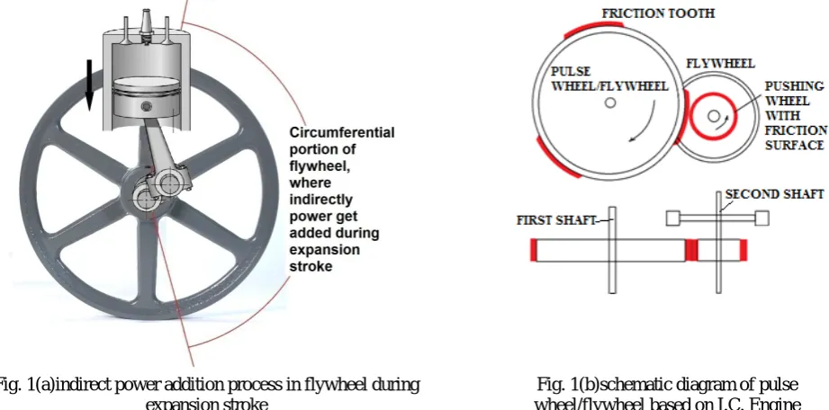
In I.C. Engine, the power added to the system is also impulsive in nature. When I.C. engine is in running state, it works on four strokes which are suction stroke, compression stroke, and expansion stroke and exhaust stroke. During the expansion stroke of a single cylinder engine, due to fuel blast in blast chamber (cylinder), thrust is produced and this produced thrust pushes the piston downward. The reciprocating motion of piston in downward direction pushes the crank for certain degrees during every 720 degree rotation. This process tends to add a power pulse indirectly to the flywheel which is attached to the engine shaft. By replacing the cylinder and crank arrangement with flywheel mounted with friction tooth on its circumference, we can directly add 2 power pulses (power equal to expansion stroke) to the flywheel in every 720 degree of its rotation. This replaced mechanism generates more power and torque than that of I.C Engine by consuming lesser amount of power than that of I.C. engine.
Fig. 1(a) describes the indirect energy addition process caused due to thrust produce on the surface of the piston during the expansion stroke of the engine.
Fig: 1(b) describes the construction of the pulse wheel/flywheel based on the technical specification of I.C. Engine, and also shows the where the arrangement of friction tooth on the circumference of wheel. The friction tooth is for delivering the power of expansion stroke to the output shaft (main shaft/output shaft without I.C. Engine) through flywheel using electric motor as an input power source. The extra small flywheel is provided on the input shaft to obtain the high power impulsive power pulse from power wheel i.e. pushing wheel. The main advantage of using pulse mechanism is that it does not need to consume fossil fuel (as electric motor is used) but is still capable of providing equivalent power as that of I.C. Engine and gives more efficiency than that of I.C. Engine. The length of friction tooth is kept equal to the stroke length of I.C. Engine whose equivalent capacity of power generating pulse wheel/flywheel is to be constructed.
Fig. 1(a)indirect power addition process in flywheel during expansion stroke
Fig. 1(b)schematic diagram of pulse wheel/flywheel based on I.C. Engine
ISSN(Online): 2319-8753 ISSN (Print): 2347-6710
I
nternational
J
ournal of
I
nnovative
R
esearch in
S
cience,
E
ngineering and
T
echnology
(An ISO 3297: 2007 Certified Organization) Vol. 4, Issue 10, October 2015
III. MATERIALS AND CONSTRUCTION OF PULSE MECHANISM
Materials required for construction of the pulse mechanism are listed below:
[01] Friction material having high coefficient of friction, high heat resisting capacity and resistance to wear & tear. [02] Highly efficient electric motor with speed controller (if RPM is more than needed).
[03] Frame structure to support rotating assembly.
[04] Pulse flywheel (flywheel with well arranged friction tooth(s)). [05] Well designed shaft and high strength bearings.
[06] Power wheel with continuous and uniform thickness friction material on its circumference.
As shown in Fig: 2, describes the construction of the pulse mechanism where, the pulse flywheel is mounted on output shaft of the mechanism. The power wheel is arrange such that, it remains in contact continuously with friction tooth during every rotation. The electric motor is used to run the power wheel mounted on input shaft of the mechanism and to transmit power to input shaft through chain drive. The alternator (electric generator) is placed at another end of the output shaft to generate the electrical power. The output shaft and the input shaft of the alternator are connected through power transmission drive, otherwise couple both shaft using flexible coupling. The distance (gap) between two adjacent friction tooth(s) must be uniform; the unequal distance will unbalance the flywheel. The length of each friction tooth must be uniform.
During the starting of pulse mechanism, electricity is given as an input from available power source through the electric motor which drives power wheel. Power is transferred from power wheel to the pulse flywheel and output shaft start to rotate at designed rpm. The generated electricity from the alternator is after provided as input to the electric motor and external power taken as input for starting mechanism is cut off. Now the system will run on its own and generates excess energy.
Fig: 2 Construction of pulse mechanism for power generation.
IV. SCOPE OF RESEARCH
ISSN(Online): 2319-8753 ISSN (Print): 2347-6710
I
nternational
J
ournal of
I
nnovative
R
esearch in
S
cience,
E
ngineering and
T
echnology
(An ISO 3297: 2007 Certified Organization) Vol. 4, Issue 10, October 2015
automotive and later that will utilise for automotive to run. The mechanism is very simple and cheap to manufacture and hence will also the better option for the P-V cells. P- V cells are unable to generate output power at night since they needs sunlight. But pulse mechanism can run for the several hours continuously.
The efficiency of the pulse mechanism exceeds 100 % hence it will be a great help to develop current and arriving technologies after making research and development in it. It is the future of the energy generation science and can’t underestimate.
V. MATHEMATICAL ILLUSTARTION
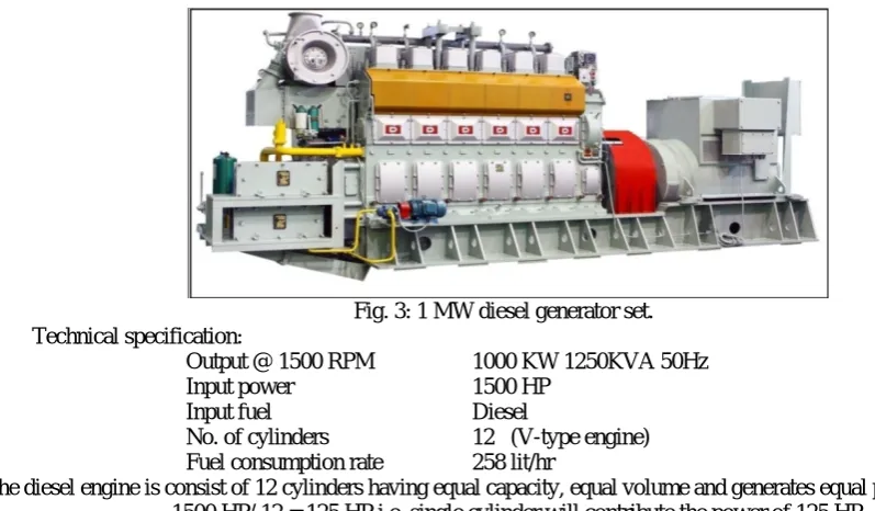
[STEP 1] Considering the 1 MW diesel generator set:-
Fig. 3: 1 MW diesel generator set. Technical specification:
Output @ 1500 RPM 1000 KW 1250KVA 50Hz
Input power 1500 HP
Input fuel Diesel
No. of cylinders 12 (V-type engine) Fuel consumption rate 258 lit/hr
The diesel engine is consist of 12 cylinders having equal capacity, equal volume and generates equal power, then 1500 HP/ 12 = 125 HP i.e. single cylinder will contribute the power of 125 HP.
[Now to design the equal capacity Pulse mechanism, assume only1 cylinder I.C. Engine of 125 HP from above 12 cylinders V-type I.C. Engine, we will consider whole 12 cylinder arrangement later.]
We have the equation,
HP = Torque (N-m) * RPM / 5252
Substituting 125 HP of single cylinder in equation to get torque generated by it, 125 = Torque* 1500 /5252
Torque= 437.66 lb-ft i.e. 593.38 Nm
(There is no need to consider the time for which the torque is applied on the crank rod by the connecting rod after the expansion stroke. For further calculations of pulse flywheel, if it is already taken in consideration during the designing of I.C. Engine it automatically get considered in specification and calculations of pulse mechanism as the phenomena and working is same.)
Assumption: It is assumed that, power wheel delivers the uniform and equal torque from power wheel to friction tooth (before and after of power transmission process) i.e. Power of each power pulse is assumed constant.
ISSN(Online): 2319-8753 ISSN (Print): 2347-6710
I
nternational
J
ournal of
I
nnovative
R
esearch in
S
cience,
E
ngineering and
T
echnology
(An ISO 3297: 2007 Certified Organization) Vol. 4, Issue 10, October 2015
Considering the radial ratio of 1:4 between pulse flywheel and power wheel Hence 60 * 1/4 = 15 cm. i.e. outermost radius of power wheel r = 0.15m
Fig.4: considered radial ratio for pulse flywheel and power wheel.
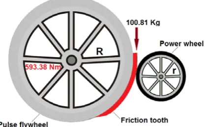
The torque generation capacity of the considered pulse flywheel of 1 friction tooth must be capable to generate the torque of 593.38 Nm in one power pulse, hence using the torque equation,
Torque (N-m) = 9.81 * radius (length in m) * mass (Kg.)
Substituting the obtained torque of single cylinder in equation, we get 593.38 N-m = 9.81* 0.60 * mass
Mass = 100.81 kg
i.e. as described in following fig.5, the mass of 100.81 Kg will act 0.6 m away from the main shaft to generate the torque of 593.38 Nm i.e. at the circumference of pulse flywheel. Since the power is being transmitted from power wheel to pulse flywheel the power wheel must have the capacity to apply 100.81 kg of impulsive force from the distance of 0.15 m on the friction tooth when they both comes in contact. Hence again using torque equation and substituting values in it we get,
Fig. 5: relation of torque between power wheel and pulse wheel
Torque = 9.81 * 100.81 * 0.15 = 148.34 Nm
ISSN(Online): 2319-8753 ISSN (Print): 2347-6710
I
nternational
J
ournal of
I
nnovative
R
esearch in
S
cience,
E
ngineering and
T
echnology
(An ISO 3297: 2007 Certified Organization) Vol. 4, Issue 10, October 2015
[ To compare the derived torque, considering the power wheel and pulse flywheel as a pinion and gear both are in contact through friction tooth resp. hence 593.38 Nm * 1 / 4 = 148.34 Nm, using relation between torque and radial ratio]
[STEP 3] Now, to find appropriate electric motor to provide power to the power wheel which must fulfill the requirement of 148.34 Nm torque for input shaft
Electric motor is of 3450 rpm and the radial ratio is 1:4 hence to maintain the constant speed of output shaft to that of alternator speed of 1500 rpm (because alternator is coupled to the output shaft directly), power wheel must be at 6000 rpm, but due to increase in speed, torque of the electric motor will reduced,
6000 / 3450 = 1.73
Multiplying by 1.73 to get the required torque of input shaft, in order to select the suitable electric motor from following specifications,
148.34 * 1.73 = 256.6 Nm
i.e. 148.34 Nm < 256.6 Nm < 258 Nm, Hence for the above torque requirement considering power losses125 HP (93 KW) motor is suitable to provide required torque of 148.34 Nm at input shaft, and the motor should be geared with the input shaft by the ratio of 1: 1.73 to maintain speed of 6000 rpm.
Table 1: specification of electric motors provided by manufacturer:
Sr. No HP KW @ 3450 rpm Torque (Nm) @ 3450 rpm
1. 50 37 103
2. 100 75 207
3. 125 93 258
4. 200 149 413
5. 400 298 826
[STEP 4] Efficiency of the mechanism due to use of pulse flywheel having 1 friction tooth instead of using 125 HP cylinder, where single tooth is designed such that it is capable to provide power of 125 HP to the output shaft during one power pulse is,
Ƞ = (output power / input power) * 100,
for pulse mechanism it becomes,
Ƞpulse mechanism= { [designed power generation capacity of one friction tooth * Numbers of friction tooth(s)] / total input power provided to the power wheel} * 100
Substituting obtained values, Ƞ = {(125 HP *1) / 125 HP} * 100
Ƞ = 100%
Now, considering for 12 cylinder V-type I.C. Engine, the number of friction tooth change to 12 tooth (as one friction stands for 1 cylinder) by considering same capacity I.C. Engine as a reference
Substituting values, Ƞ = {(125 HP * 12) / 125 HP}* 100
Ƞ = 1200%
The losses in the pulse mechanism are automatically get considered, as for 1000 KW power generation 1500 HP power is provided through diesel generator set instead of providing 1340 HP which equals to 1000 KW power, which shows that power losses are considered during the designing of I.C. Engine hence there is no need to subtract the losses from the obtained efficiency of pulse mechanism when it designed by using I.C. Engine parameters.
{If the pulse wheel/flywheel is directly designed without consideration of I.C. Engine then, subtract all the
system losses like slipping losses, heating losses, vibration losses including frictional losses of bearings from the overall output power.}
ISSN(Online): 2319-8753 ISSN (Print): 2347-6710
I
nternational
J
ournal of
I
nnovative
R
esearch in
S
cience,
E
ngineering and
T
echnology
(An ISO 3297: 2007 Certified Organization) Vol. 4, Issue 10, October 2015
output shaft i.e. As required to the alternator, this is equivalent to the torque and rpm generated by the 12 cylinder V type I.C Engine and it is mathematically proved.
If the number friction tooth increased then it greatly affects the efficiency of mechanism, since there is no need to increment the input power in the mechanism i.e. input power remains const.
Example [01]:-
No. of friction tooth changed to 20(I/p power constant) then, Ƞ = (125 HP * 20) / 125 HP * 100
Ƞ = 2000 %
Here 20 power pulses are added into pulse flywheel in one rotation, hence efficiency increase and will keep increasing till the numbers of friction tooth on a pulse flywheel kept increasing which confirms that, for pulse flywheel Efficiency is Unbounded.
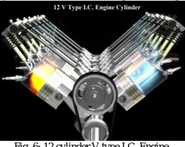
The Fig: 6, illustrates that, in 12 cylinder V type I.C. Engine the expansion stroke is designed to take place in uniform intermittent cycle, and it can be see that the position of each cylinder is different at same instant of time. The sequence of the expansion stroke varies along with the engine designer. Considering the sequence is 1-4-9-7-12-6-8-3-11-2-5-10 and comparing it with the pulse wheel/flywheel having 12 friction tooth(s) on it circumferential surface, but the I.C. Engine is 4 stroke mechanism, hence 6 cylinders out of 12 cylinders complete their expansion stroke in 1st rotation (1-4-9-7-12-6)and remaining 6 cylinders (8-3-11-2-5-10) complete their expansion stroke in next 2nd rotation.
Fig. 6: 12 cylinder V type I.C. Engine
i.e. 12 expansion strokes in 2 rotations but, due to design of pulse flywheel 12 expansion stroke can be made in a single rotation due to 12 friction tooth(s). This is the advantage of pulse mechanism over I.C. Engine mechanism.
Considering this characteristic constructional property of pulse mechanism, it completes 24 expansion strokes in 2 rotations as compared to that of 12 cylinder 4 stroke I.C. Engine, the above obtained efficiency becomes,
Ƞ = {(125 HP * 24) / 125 HP}* 100
Ƞ = 2400 %
i.e. again efficiency increases (since power delivered in the output shaft of the mechanism is increased), because even the pulse mechanism is designed considering 12 cylinder v-type engine but, the pulse mechanism completes 24 expansion strokes in two rotations where 12 cylinder v-type engine completes only 12 expansion strokes in 2 rotation as the formula for both is same hence total number of expansion strokes in 2 rotations are considered. To generate the
equivalent amount of power as that of 12 cylinder v-type I.C. Engine, 6 friction tooth(s) pulse are sufficient.
Even considering power transmission losses from power wheel to pulse wheel/flywheel and slipping losses up to 1000% (which shows huge power lose is taken into consideration), efficiency comes to 3000% - 1000 % = 2000 %,still efficiency stands away 100 %.
Design process for pulse wheel/flywheel:
(Only for pulse flywheel of radius ‘R’ and power wheel of radius ‘r’)
ISSN(Online): 2319-8753 ISSN (Print): 2347-6710
I
nternational
J
ournal of
I
nnovative
R
esearch in
S
cience,
E
ngineering and
T
echnology
(An ISO 3297: 2007 Certified Organization) Vol. 4, Issue 10, October 2015
To obtain the required circumferential area of the flywheel these four factors should be taken into account, [01] Length of the friction tooth
[02] Distance (gap) between two adjacent friction tooth(s) [03] Available floor area (compactness)
[04] Thickness of friction tooth material
Among these factors, the Length of the friction tooth and the Distance (gap) between two adjacent friction tooth(s) is very important to obtain the values of ‘R’ and ‘r’.
[For radius ‘R’]
Considering the length of friction tooth is 20 cm (200 mm): L= 20 cm. Number of friction tooth on wheel/flywheel is 16: X=16
Distance / Gap between two adjacent friction tooth is kept 5cm: G=5 cm. Total length of circumference of the flywheel = C
Then,
Total required circumferential length = (no. of friction tooth * length of friction tooth) + (no. of friction tooth * Distance / Gap between two adjacent friction tooth) C = (X * L) + (X * G)
C = X * (L + G)
= (16 * 20) + (16 * 5) = 400 cm
i.e. Circumference required to construct pulse flywheel is 400 cm. We know the formula for circumference of circle = 2 Π R , substituting values
400 = 2* Π * R Hence R = 63.66 cm
Now, assuming that thickness of the friction tooth is 1 cm then outer most radius of pulse wheel/flywheel R = 63.66 CM + 1
R= 64.66 cm
[For radius ‘r’]
The radius of power wheel is related with the radius of pulse wheel/flywheel. Generally the radial ratio between the radii of pulse wheel/flywheel and power wheel is taken as 1:3, 1:4, 1: 5 or more. Greater the radial ratio smaller the I/P torque required.
Considering the radial ratio between power wheel and pulse wheel/flywheel to be 1:4 Hence, r = R * radial ratio
i.e. r = 64.66 * 1 /4 r = 16.16 cm
r = 16.16 cm is the outer most radius of the power wheel (with consideration of 1 cm thick friction material on flywheel’s circumferential surface). If the thickness of friction material on the power wheel is assumed to 2 cm thick then actual radius ‘r’ i.e. radius without friction material for power wheel must be
r = 16.16 – 2 cm i.e. r = 14.16 cm
The radial ratio is very important to maintain the constant speed of the output shaft at the design values. If the number of friction tooth(s) increases, it also essential to increase the radius of flywheel to make available the required circumferential distance for the increased friction tooth i.e. new radius ‘R’ will obtain. To avoid constructional complications multiply the radial ratio with the modified radius ‘R’ and get the suitable value of radius ‘r’ for power wheel. If one does not want to change the radius ‘r’ then speed of the input shaft have to increase in order to maintain required RPM.
[It should be noted that the distance between two adjacent friction tooth(s) should not be too low. If the two
ISSN(Online): 2319-8753 ISSN (Print): 2347-6710
I
nternational
J
ournal of
I
nnovative
R
esearch in
S
cience,
E
ngineering and
T
echnology
(An ISO 3297: 2007 Certified Organization) Vol. 4, Issue 10, October 2015
mechanism because that system will run on gradual power addition phenomena, and pulse wheel/flywheel is based on
impulsive power pulse addition and is designed accordingly.]
VI. DESIGNATED RESULTS
[01] In pulse mechanism, due to the use of the pulse wheel/flywheel, the efficiency of the mechanism exceeds 100%. [02] The numbers of friction tooth(s) fixed on the flywheel does not affect the efficiency of the machine as it is
already assumed that the electric motor i.e. power wheel provides power pulse of uniform power.
[03] On performing above calculations efficiency obtained exceeds 3000% which shows high chances of getting excess output in actual practical working.
[04] As the number of friction tooth increases, the efficiency of the whole system increases.
[05] Huge power and torque can be generate as that of multi cylinder I.C. Engine by providing less amount of energy as input.
[06] As the input power of electric motor increases, the power and torque output of the same mechanism increases.
VII. CONCLUSION
The pulse wheel/flywheel could be the future of energy generation, and possesses the capability to provide the system efficiency beyond 100%,even considering all types of losses present in overall working. This means that, there are higher chances to get large amount of excess output energy in actual working of the pulse mechanism.
It violates the current laws of physics which states that “the efficiency of any machine cannot exceed 100%” but on performing calculations it gets proved that the efficiency for pulse mechanism stands unbounded.
REFERENCES
[01] Patrick J. Kelly “Gravity-Powered Systems” From A Practical Guide To Free-Energy Devices. [02] Chas Champbel’s System.
[03] Domkundwar, ., “Internal Combustion Engines”, Dhanpat Rai & Co. New Delhi. [04] Willard W Pulkrabek. “Internal Combustion Engines”, Pearson Education.
[05] Shyam K. Agrawal, “Internal Combustion Engines”, New Edge International Publication. [06] K.K. Ramalingam, “Internal Combustion Engines”, Scitech Publication.
[07] V. Ganeshan, “Internal Combustion Engines”,2/E, Tata Mcgraw Hill, New Delhi.
[08] E. F. Obert , “Internal Combustion Engines And Air Pollution”, Harper And Row, New York.
[09] Shigley J.E. And Mischke C.R., “Mechanical Engineering Design”, Tata Mcgraw Hill Publication Co. Ltd. [10] Juvinal R.C., “Fundamentals Of Machine Components Design”, John Wiley And Sons.
[11] S. S. Rattan, Theory Of Machines, Tata Mcgraw Hill, New Delhi. [12] Theory Of Machines, Longman’s Green & Co., London.
[13] J.S.Rao. The Theory Of Machines Through Solved Problems ,New Age International Publishers.
[14] Chun-Chao Wang, Yuh-Suiang Wang “Gravity Power Generation Mechanism” United States Patent Number: 20090115195 A1 App No- 11/935,228 May, 2009.
[15] R.S.Khurmi, “ A Textbook Of Machine Design”, S. Chand Technical.
BIOGRAPHY
Saurabh Vikas Chaudhari studying in last year of mechanical engineering in J.T. Mahajan College of Engineering, Faizpur (Maharashtra). He is working on gravity based power generation systems and has applied for Patent. He researched and collaborate the gravitational theories of Sir Isaac Newton and Mr. Lawrence Tseung to generate energy. He puts the pulse mechanism based on I.C Engine working phenomena and using mathematical calculation he derived, that the efficiency of mechanism due to use of the pulse wheel/flywheel exceeds 100%.