SIMULATION OF BI-METALLIC INTERFACIAL CRACKS USING
ELEMENT FREE GALERKIN METHOD
Mohit Pant1, Kamal Sharma2 1
Associate Prof., Deptt. of Mech. Engg., Graphic Era University Dehradun, INDIA-248002 2
SO “E”, Reactor Safety Division, Bhabha Atomic Research Centre, Trombay, Mumbai, INDIA-400085 E-mail of corresponding author: [email protected]
ABSTRACT
This paper presents the implementation of element free Galerkin method for the stress analysis of structures having cracks at the interface of two dissimilar materials. The material discontinuity at the interface has been modeled using a jump function with a jump parameter that governs its strength. The jump function enriches the approximation by the addition of special shape function that contains discontinuities in the derivative. The trial and test functions of the weak form are constructed using moving least-square interpolants in each material domain. An intrinsic enrichment criterion with enriched basis has been used to model the crack tip stress fields. The mixed mode (complex) stress intensity factors for bi-material interface cracks are numerically evaluated using the modified domain form of interaction integral. The numerical results are obtained for edge and centre cracks lying at the bi-material interface, and are found to be in good agreement with the reference solutions for the interfacial crack problems.
INTRODUCTION
The increasing demand of multifunctional materials (having resistance to corrosion, wear, stiffness, thermal and chemical resistance) in mechanical, aerospace and biomedical applications has imparted the layered materials, a coveted place in the world of engineering materials. Layered materials are found in a variety of important structures such as adhesive joints, composite laminates, and various electronics and optic components. The interaction between materials results in local load distribution and determines the overall strength and fracture behavior. The abrupt change in properties at the interface is one source of failure of layered materials, unlike the behavior of homogeneous [1] materials. Unlike crack problems in homogeneous bodies, the bi-material interface crack always induces both opening and shearing mode behavior for mode-I loading. This coupling of stress intensification was first demonstrated by Williams [2] who used an Eigen function expansion approach. The stress singularity in the vicinity of a crack tip of a bi-material interface crack is oscillatory in nature along with the presence of
r
/
1 singularity [2]. Various numerical methods for evaluating the stress intensity factors of bi-material interface cracks have been developed such as finite element method (FEM) and boundary element method (BEM). Yau et al. [3] applied the M- integral method with FEM. Matos et al. [4] used the virtual crack extension method in conjunction with the superposition method and FEM. Miyazaki et al. [5-6] applied the virtual crack extension method and M- integral method with BEM. Ikeda et al. [7] presented the efficient numerical procedures in conjunction with FEM for the analysis of an interface crack under thermal stresses. Bi-material interface cracks have also been simulated by using extended finite element method (X-FEM) [8].
In the present work, EFGM has been implemented for the analysis of interface cracks lying between two dissimilar materials. The material discontinuity at the interface is modeled using jump function with a jump parameter that governs its strength. The jump function enriches the approximation by the addition of special shape function that contains discontinuities in the derivative. The trial and test functions of the weak form are constructed using moving least-square interpolants in each material domain. A standard intrinsic enrichment criterion with enriched basis has been used to model the crack tip stress fields. The mixed mode stress intensity factors for bi-material interface cracks are numerically evaluated using the modified domain form of interaction integral approach.
REVIEW OF ELEMENT FREE GALERKIN METHOD
In EFGM, a field variable is approximated by moving least square approximation function [9], which is given by
u uh(x)
(1)
) ( ) ( ) ( ) ( ) (
1
x a x p x x
x m T
j j j
h
a p
u = ∑ ≡
where, p(x) is a vector of basis functions, are unknown coefficients, and is the number of terms in the basis. The unknown coefficients are obtained by minimizing a weighted least square sum of the difference
between local approximation, and field function nodal parameters . The weighted least square sum can be written in the following quadratic form:
) (x
a m
) (x a
) (x
h
u uI L(x)
= ∑ − − (2)
= n
I I
T
I u
w L
1
2
] )[
( )
(x x x p (x)a(x)
where, uI is the nodal parameter associated with node I at ; are not the nodal values of because
is an approximant and not an interpolant;
I
x uI uh(x−xI)
) (x
h
u w(x−xI) is the weight function having compact support
associated with a node I , and is the number of nodes in the domain of influence of the point , n x w(x−xI)≠0. By setting ∂L/∂a=0, a following set of linear equation is obtained as:
u x B x a
A(x) ( )= ( ) (3)
By substituting Eq. (3) in Eq. (1), the approximation function is obtained as:
I (4)
n
I I h
u
Φ
u = ∑
=1 ) ( )
(x x
GOVERNING EQUATIONS OF BI-MATERIAL
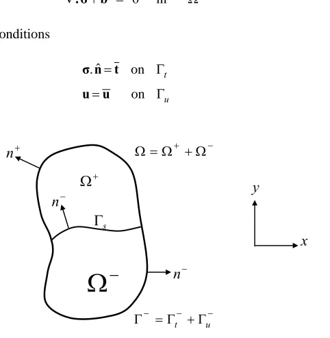
The treatment of material discontinuity in the EFGM is demonstrated by considering a linear elastostatic problem. For simplicity, two distinguishable materials separated by a single interface, as shown in Fig. 1 is considered. This interface is defined by
s
Γ
n , the unit outward normal of Ω− along the material boundary. The governing equilibrium equation is given by
Ω =
+
∇.σ b 0 in (5)
along with associated boundary conditions
σ.nˆ=t on Γt (6)
u=u on Γu (7)
−
Ω
+ Ω −
n
s Γ
−
n
− − − =Γ +Γ
Γ t u
− + +Ω Ω = Ω +
n
x y
where, σis the Cauchy stress tensor and is a body force vector, b t is the specified traction on a surface, uis the specified displacement field and is the unit normal to the domain. A perfect interface has been assumed, and hence the traction and displacement are assumed to be continuous across the interface
nˆ
s
Γ .
MODIFICATIONS FOR MATERIAL DISCONTINUITY
Few modifications and additions are introduced in EFGM to solve the bi-material interface crack problems. Material discontinuity i.e. weak discontinuity has been modeled by a jump function and interface crack i.e. strong discontinuity has been modeled by intrinsic enrichment criterion. These changes provide EFGM an ability to solve the problems involving material discontinuities. The modifications in the approaches are discussed below:
Jump Function Approach
In this approach, the discontinuities in derivatives are incorporated by using a jump function in the solution. The enrichment of EFGM approximations is done by adding special shape functions (jump functions) that contain discontinuities in the derivative [10, 11]. The jump shape functions have compact support which results in banded matrix equations. Consider a two dimensional model having lines at which discontinuities in derivatives exist, then the approximation becomes
d
n
(8)
∑ Ψ
+ =
=
d
J J
J EFGM
h u n q s r
u
1
) ( ) ( )
( )
(x x
where uEFGM(x) is the standard EFGM approximation, which is given as
(9) ∑
=
=
n
I I I
h Φ u
u
1 ) ( )
(x x
J
q is the jumps amplitude parameters, ΨJ
( )
r are the jump shape functions, and s provides parameterization of theline of discontinuity. qJis discretized as follows:
( )
( )
J J
I I I
q s =
∑
N s q (10)where,NI are one dimensional shape functions which need to be so that they do not introduce any
discontinuities in the derivatives except at the discontinuity line. From Eq. (8), it is clear that the constant and linear fields will still be reproduced exactly when . The distance to a closest point on the line of discontinuity is denoted by , which is taken positive on one side of the discontinuity and negative on the other side. The jump shape function is constructed from the polynomials with a built-in discontinuity in the derivatives. Let
1 C
0 =
J
q
r
J
Ψ be equal
toΨJ
( )
rJ , where rJ=r dJ mI ; rJis the distance to the Jthpoint of discontinuity and is the domain of influence.A cubic spline jump function [10] used in the present work is given by,
mI
d
( )
61 3 12 2 12 16, 10, 1
J J J J J J
J
r r r r
r
r −
⎧ + − + ≤ ⎫
⎪ ⎪
Ψ = ⎨ ⎬
≥
⎪ ⎪
⎩ ⎭
(11)
NUMERICAL IMPLEMENTATION
The numerical implementation of the present work was carried out using MATLAB programming. A cubic spline weight function was used for generating the EFGM shape functions along with a domain scaling parameter . The numerical evaluation of stress intensity factor was carried out using interaction integral method. The geometry has been discretized using 25 uniformly distributed nodes along
) 5 . 1 (dmax =
along -direction i.e. total 1250 (25x50) nodes and 1176 (24x49) background cells. The mixed mode stress intensity factors and were evaluated using the domain form [12] of the contour interaction integral [3]. The domain form of interaction integral [13] can be written as
y
I
K KII
(12) dA
q u u
i
I j ij iaux ijaux i j
A
aux ik
k 1 ,1 ,1) ,
(σ ε δ −σ −σ
∫ − =
where, is an arbitrarily smooth scalar weighting function that is unity at the crack tip and zero on the contour C. The auxiliary displacement fields for an interfacial crack can be extracted using the stated equations, and the interaction integral is related to the stress intensity factors through the relation [14].
q
) (
) ( cosh
2
2 *
aux II I aux II
IK K K
K E
I = +
πε (13)
aux I
K and are local auxiliary stress intensity factors for the auxiliary fields and is the equivalent
Young’s modulus and
aux II
K E*
ε
is the bimaterial constant [13] of the bi-material system. By selecting andand evaluating
1
=
aux I
K
0
=
aux II
K
I
, one can compute KI and can proceed in an analogous way to evaluateKII.RESULTS AND DISCUSSIONS
Two different cases of bi-material interface cracks have been considered in this study. In both the cases, the crack remains parallel to the interface. A plane stress condition has been assumed. The results are presented in the form of normalized SIF asKi σ πa .
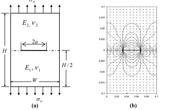
Edge Crack Bi-material Plate under Tension
A bi-material plate having an edge crack of length a, is subjected to traction on upper and lower
boundaries as shown in Fig. 2a. The plate dimensions are scaled with, W =3 units, and far field
applied stress . The values of Poisson’s ratios are taken as . In order to demonstrate the
validity of the proposed method for edge interface crack problems, the results are obtained for the several ratios of
Young’s moduli , and crack lengths
units 9 =
H
unit 1 =
o
σ ν1=ν2 =0.3
100 , 10 , 2 / 1
2 E =
E a/W =0.2, 0.3, 0.4, 0.5, 0.6, where is kept fixed
at 100 units. The results in Ref.1 are taken from Matsumto et al. [15] and in Ref.2 are taken from Liu et al. [16]. 1
E
H
W
a
o
σ
o
σ
1 1,
ν
E
2 2,ν E
Fig. 2: Stress-Strain contours over the domain
Contour plots shown in Fig. 2 shows that stress ( ) are continuous (Fig. 2b) while a significant jump is
present in the magnitude of strain (
yy σ
yy
ε
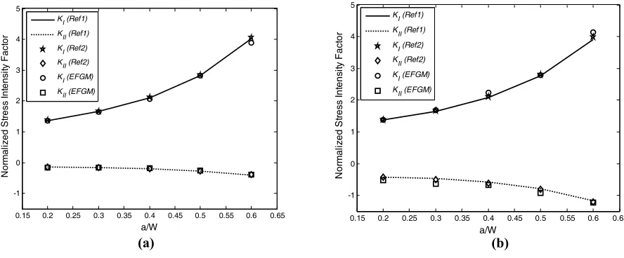
) at the interface (Fig. 2c). Figure 3a shows the variation of normalized stressintensity factors i.e. and with varying crack length for . The results show that with increase in
crack length, is increasing while goes on decreasing. Next, the EFGM results are obtained for
by increasing the length of the crack as shown in Fig. 3b. It can be clearly seen from Fig. 3 that the values obtained by EFGM are quite close to the reference values. The maximum percentage difference of EFGM results with reference solutions is less than 4%. From these simulations, it is noticed that the discontinuity in strain field has been observed due to the change in material property i.e. Young’s moduli at the interface.
I
K KII E2/E1=2
I
K KII
100 / 1
2 E = E
0.15 0.2 0.25 0.3 0.35 0.4 0.45 0.5 0.55 0.6 0.65 -1
0 1 2 3 4 5
a/W
N
or
m
al
iz
ed
S
tre
ss
In
te
ns
ity F
act
or
KI (Ref1) KII (Ref1) KI (Ref2) KII (Ref2) KI (EFGM) KII (EFGM)
0.15 0.2 0.25 0.3 0.35 0.4 0.45 0.5 0.55 0.6 0.65 -1
0 1 2 3 4 5
a/W
N
or
m
al
iz
ed
S
tre
ss
In
tens
ity
F
ac
tor
KI (Ref1) KII (Ref1) KI (Ref2) KII (Ref2) KI (EFGM) KII (EFGM)
Fig. 3: SIF variation for different ratio of E2/E1
(a) (b)
Centre Crack Bi-material Plate under Tension
A rectangular bi-material plate with an interface crack at the center has also been considered as shown in Fig. 4a. The width (W) and height (H ) of the plate are taken as 100 mm and 200 mm respectively. The material interface is kept horizontal at a distance of H
2
from the bottom of plate. A tensile load of 9.8 MPa is applied in a direction normal to the interface. Two different cases of crack length, 2a i.e. 40 and 80 mm are considered. Young’s modulus of the lower material (E1) is kept constant at 205.8 GPa.For both material 1 and 2, the values of Poisson’s ratio are taken as 0.3. The results are obtained for different ratios of Young’s modulus. The results are normalized as Ki σ πa (i=1, 2) so as to obtain non-dimensional values corresponding to both mode-I and mode-II stress intensity factor. The results are compared with the available results in the literature i.e. Ref.1 [5] and Ref.2 [8] obtained by BEM and X-FEM respectively.
For a particular crack length and E2/E1 =100, the contours of σyy and
ε
yy were plotted in order to have a clear visualization of stress and strain fields along with establishing the modeling capability of the method. Contour plots shown in Fig. 4 shows that stress ( ) are continuous (Fig. 4b) while a significant jump is present inthe magnitude of strain (
yy σ
yy
ε
) at the interface (Fig. 4c). This jump in the magnitude of strain is due to the sudden change of material property at the interface.Figure 5a shows the variation of normalized stress intensity factors with the variation of for a crack length of 40 mm. The values of stress intensity factors have been evaluated at the right tip of the crack. The
analysis shows that the normalized values of and show a decreasing trend with the increase in .
Moreover, the results obtained by EFGM are quite close to the reference solutions. Another simulation is performed 1 2 /E E
I
for a crack length of 80 mm, and the results are plotted in Fig. 5b. From the results presented in Fig. 5, it can be clearly seen that the EFGM results are in good agreement with the reference solutions available in the literature. The EFGM results are plotted along with the reference solution as shown in Fig. 5. The values of are found to be
quite close to Ref.1 solution with a maximum error of 5% for .
I
K
100 / 1
2 E = E
From these two simulations of bi-metallic interfacial cracks it was observed that the EFGM in capable in modeling the interfacial cracks in an efficient way for a wide range of crack length and material incompatability. Moreover, the stress-strain contours prove the capability of jump function criterion in EFGM to simulate the derivative discontinuity at the bimaterial interface. Thus, the merits EFGM method over the traditional mesh based method can also be exploited for simulating the crack propagation problems in bi-materials.
H
W a
2
2 / H
o
σ
o
σ 1 1
,
ν
E
2 , 2
ν
E
Fig. 4: Stress-Strain contours over the domain
(a) (b) (c)
-0.5 0 0.5 1 1.5 2 2.5 3 3.5 4 4.5 5 -0.4
-0.2 0 0.2 0.4 0.6 0.8 1 1.2 1.4
ln (E2/E1)
N
or
m
al
iz
ed S
tres
s I
nt
ens
ity
F
ac
tor
KI (Ref1) KII (Ref1)
KI (Ref2) KII (Ref2)
KI (EFGM)
KII (EFGM)
-0.5 0 0.5 1 1.5 2 2.5 3 3.5 4 4.5 5 0
0.5 1 1.5 2
ln (E2/E1)
N
or
m
al
iz
ed
S
tre
ss
In
te
ns
ity F
act
or
KI (Ref1) K
II (Ref1)
KI (Ref2) KII (Ref2) KI (EFGM) K
II (EFGM)
Fig. 5: SIF variation for different crack lengths
CONCLUSION
In the present work, element free Galerkin method has been implemented for the analysis of interfacial cracks lying between two dissimilar materials. The material discontinuity at the interface has been modeled by a jump function, which enriches the approximation by addition of special shape function that contains discontinuities in the derivative. The crack has been modeled by an intrinsic enrichment criterion. The mixed mode stress intensity factors for bi-material interface cracks are numerically evaluated using the modified domain form of interaction integral approach. The numerical results were obtained for an edge crack and a centre crack lying at the interface of bi-material. The numerical results obtained by EFGM were found in good agreement with those available in literature for both interfacial crack problems. This method for the treatment of bi-material interfacial cracks is quite simple from the implementation point of view as in this approach, a discontinuity in materials was modeled though a jump function, and a crack at the material interface was modeled by intrinsic enrichment only. The simplicity and accuracy of this implementation shows that it can be further applied to study and analyze the complex interfacial failures of multi-layered dissimilar materials.
REFERENCES
[1] Hutchinson, J.W., Suo, Z., “Mixed mode cracking in layered materials”, Advance Applied Mechanics, Vol. 29, 1991, pp. 63-191.
[2] Williams, M.L., “The stress around a fault or crack in dissimilar media”, Bulletin of the Seismology Society of America, Vol. 49, 1959, pp. 199-204.
[3] Yau, J.F., Wang, S.S., “An analysis of interface cracks between dissimilar isotropic materials using conservation integral in elasticity”, Engineering Fracture Mechanics, Vol. 20, 1984, pp.423-432.
[4] Matos, P.P.L., Meeking, R.M., Charalambides, P.G. and Drory, M.D., “A method for calculating stress intensities in bimetal fracture”, International Journal of Fracture, Vol. 40, 1989, pp. 235-254.
[5] Miyakazi, N., Ikeda, T., Soda T., Munakata, T., “Stress intensity factor analysis of interface crack using boundary element method (application of virtual crack extension method)”, JSME International Journal: Series A, Vol. 36, 1993, pp.36-42.
[6] Miyakazi, N., Ikeda, T., Soda T., Munakata, T., “Stress intensity factor analysis of interface crack using boundary element method (application of contour integral method)”, Engineering Fracture Mechanics, Vol. 45, 1993, pp. 599-610.
[7] Ikeda, T., Sun, C.T., “Stress intensity factor analysis for an interface crack between dissimilar isotropic materials under thermal stress”, International Journal of Fracture, Vol. 111, 2001, pp. 229-249.
[8] Nagashima, T., Omoto, Y., Tani, S., “Stress intensity factor analysis of interface cracks using X-FEM”, International Journal for Numerical Methods in Engineering, Vol. 56, 2003, pp. 1151-1173.
[9] Nguyen, P., Rabczuk, T., Bordas, S., and Duflot, M., “Meshless methods: A review and computer
implementation aspects”, Mathematics and Computers in Simulation, Vol. 79, 2008, pp. 763-813.
[10] Batra, R.C., Porfiri, M., and Spinello, D., “Treatment of material discontinuity in two meshless local Petrov– Galerkin (MLPG) formulations of axisymmetric transient heat conduction”, International Journal for Numerical Methods in Engineering, Vol. 61, 2004, pp. 2461–2479.
[11] Krongauz, Y., Belytschko, T., “EFG Approximation with discontinuous derivatives”, International Journal for Numerical Methods in Engineering, Vol. 41, 1998, pp.1215-1233.
[12] Moran, B., Shih, C.F., “Crack tip and associated domain integrals from momentum and energy balance”, Engineering Fracture Mechanics, Vol. 27, 1987, pp. 615-641.
[13] Yau, J.F., Wang, S.S., and Corten, H.T., “A mixed-mode crack analysis of isotropic solids using conservation laws of elasticity”, Journal of Applied Mechanics, Vol. 47, 1980, pp. 335-341.
[14] Sukumar, N., Huang, Z.Y., Prevost, J.H., and Suo, Z., “Partition of unity enrichment for bimaterial interface cracks”, International Journal for Numerical Methods in Engineering, Vol. 59, 2004, pp. 1075-1102.
[15] Matsumto, T., Tanaka, M., and Obara, R., “Computation of stress intensity factors of interface cracks based on interaction energy release rates and BEM sensitivity analysis”, Engineering Fracture Mechanics, Vol. 65, 2000, pp. 683-702.