ABSTRACT
BAI, XIAO. Processing and Characterization of Functionally Graded Hydroxyapatite Coatings for Biomedical Implants. (Under the direction of Dr. Afsaneh Rabiei).
Hydroxyapatite [Ca10(PO4)6(OH)2, HA] has been widely applied as a coating on various
biomedical bone/dental implants to improve biocompatibility and bioactivity. It has been observed that primary reasons leading to implantation failure of commercial HA coated implants processed by plasma spraying are the poor mechanical properties of coatings and infections accompanied by implantation. It has been also reported an ideal coating should be able to stimulate new bone growth at the initial stage of implantation and stay stable both mechanically and chemically thereafter. This research has investigated a functionally graded hydroxyapatite (FGHA) coating that is capable of improving the stability of implants,
facilitating recovery, and preventing infections after implantation.
A series of FGHA coatings with incorporated Ag 0 ~ 13.53 wt. % has been deposited onto Ti substrate using ion beam assisted deposition (IBAD) with in-situ heat treatment. The compositional, microstructural, mechanical, and biological properties of coatings have been analyzed via various tests. The relationship among processing parameters, coating properties and biological behaviors has been established and the processing parameters for processing FGHA coatings with/without incorporated Ag have been optimized.
coatings are dense and have a gradually decreased crystallinity from substrate/coating interface to top surface. In particular, the interface has an atomically intermixed structure; the region near the interface has a columnar grain structure whereas the region near coating top surface is mostly amorphous. TEM / STEM observation of FGHA coating with
Processing and Characterization of Functionally Graded Hydroxyapatite Coatings for Biomedical Implants
by Xiao Bai
A dissertation submitted to the Graduate Faculty of North Carolina State University
in partial fulfillment of the requirements for the degree of
Doctor of Philosophy
Mechanical Engineering
Raleigh, North Carolina June 2009
APPROVED BY:
_______________________________ ______________________________ Dr. Afsaneh Rabiei Dr. Gregory Buckner
Committee Chair
DEDICATION
BIOGRAPHY
ACKNOWLEDGMENTS
First and foremost, I would like to express my deep gratitude to Dr. Rabiei, my dissertation advisor, for offering me the opportunity to work on this project. Without her genuine encouragement and wise guidance over the past four years, this work could have never been done. Furthermore, I have been greatly impressed by her profound insight into cross-disciplinary research and perseverance in pursuing innovative research that will benefit my future career.
I would like to offer my sincere thanks to my committee members Dr. Buckner, Dr. Roberts, and Dr. Rigsbee, for their valuable time dedication in completing this work. Special thanks go to Dr. Rigsbee for providing the pull off tester to conduct experiments at the beginning of this project.
Thanks also go to all the members of our research group including former graduate students Mr. Travis Blalock, Ms. Adit Shah, Dr. Brian Neville, Dr. Lakshmi Vendra, and current graduate student Mr. Stefan Sandukas for their assistance and suggestions in completing this work. I would like to thank Mr. Rufus Richardson and Mr. Mike L. Breedlove at machine shop for their assistance in manufacturing tools for our experiments, as well as staffs at main office for their help in processing the orders and shipping associated with this project.
TABLE OF CONTENTS
LIST OF FIGURES ... viii
LIST OF TABLES... xiv
CHAPTER 1 INTRODUCTION ... 1
1.1 Hydroxyapatite (HA) coatings... 1
1.2 Factors determining performance of HA coatings... 4
1.3 Problems associated with current HA coatings ... 7
1.4 Functionally graded CaP/HA coatings processed by ion beam assisted deposition with in situ heat treatment... 10
1.5 Functionally graded CaP/HA coatings with incorporated antimicrobials ... 12
1.6 Objectives ... 14
CHAPTER 2 LITERATURE REVIEW ... 17
2.1 HA... 17
2.1.1 Chemistry of HA... 17
2.1.2 Physical properties of HA... 21
2.1.3 Applications of HA ... 22
2.1.4 Mechanisms of bone growth on HA coatings... 26
2.1.5 Impacts of HA’s properties on its performance... 28
2.2 Processing of HA ... 31
2.2.1 Synthesis of HA powders ... 31
2.2.2 Processing of dense HA ... 33
2.2.3 Processing of HA coatings... 34
2.3 Functionally grade HA/CaP coatings... 54
2.4 HA/CaP coatings with antimicrobials... 55
2.4.1 Mechanisms of antibacterial effect of Ag/Ag+... 56
2.4.2 Processing methods of doping Ag/Ag+ in coating ... 56
2.4.3 Antibacterial effects and cytotoxicity of Ag-doped HA ... 58
2.5 Summary... 61
CHAPTER 3 CALCIUM PHOSPHATE / HYDROXYAPATITE COATINGS ON HEATED SUBSTRATES AT VARIOUS TEMPERATURES ... 62
3.1 Introduction... 62
3.2 Materials and methods ... 64
3.2.3 Processing of set temperature coatings ... 70
3.2.4 Characterization methods... 73
3.3 Results... 78
3.4 Discussion... 101
3.5 Summary... 109
CHAPTER 4 FUNCTIONALLY GRADED CALCIUM PHOSPHATE / HYDROXYAPATITE COATINGS... 111
4.1 Introduction... 111
4.2 Materials and methods ... 112
4.2.1 Substrate and target... 112
4.2.2 Ion beam assisted deposition system ... 113
4.2.3 Processing of functionally graded coatings ... 113
4.2.4 Characterization methods... 114
4.3 Results... 118
4.3.1 Microstructural analysis and crystallinity evaluation ... 118
4.3.2 Compositional analysis ... 125
4.3.3 Surface morphology... 129
4.3.4 Mechanical properties... 131
4.3.5 Biological response... 134
4.4 Discussion... 137
4.5 Summary... 140
CHAPTER 5 FUNCTIONALLY GRADED CALCIUM PHOSPHATE / HYDROXYAPATITE COATINGS INCORPORATED WITH ANTIMICROBIAL COMPONENT... 141
5.1 Introduction... 141
5.2 Materials and methods ... 143
5.2.1 Substrates ... 143
5.2.2 Hydroxyapatite targets ... 143
5.2.3 Silver wires ... 144
5.2.4 Ion beam assisted deposition system. ... 144
5.2.5 Processing of functionally graded coating incorporated with Ag... 146
5.2.6 Characterization methods... 148
5.3 Results... 156
5.4 Discussion... 190
5.5 Summary... 197
CHAPTER 6 CONCLUSION... 199
LIST OF FIGURES
Figure 2- 1 Schematic drawing of HA lattice [9]. ... 18
Figure 2- 2 HA coated dental screw (top) [77] and femoral stem of total hip replacement (bottom) [78]... 24
Figure 2- 3 Schematic diagram of establishment of bone-implant bonding [31] ... 27
Figure 2- 4 Scheme of plasma spraying process [91] ... 36
Figure 2- 5 SEM images of the surface of HA coating produced by plasma spraying [89]... 36
Figure 2- 6 Scanning electron micrograph of the surface of HA coating produced by Sol-Gel [89]... 39
Figure 2- 7 Schematic drawing of electrophoreses cell for membrane method [52]... 41
Figure 2- 8 SEM image of cross section of sintered HA coating deposited using EPD on TiAlV substrate [53] ... 41
Figure 2- 9 SEM image of cross section of HA-coated Ti after HIP at 850 oC and 1000 bar [58]... 44
Figure 2- 10 Schematic of PLD system [103] ... 44
Figure 2- 11 Schematic drawing of sputtering deposition [105] ... 46
Figure 2- 12 Representative surface morphology of sputtered CaP coatings on glass substrate. (A) As-sputtered surface (X20 K); (B) 400°C heat treatment for 1 h (X20 K); (C) 400°C heat treatment for 4 h (X20 K) [1]... 47
Figure 2- 13 Schematic diagram of ion beam dynamic mixing apparatus [66]... 48
Figure 2- 14 Scheme of IBAD [117] ... 51
Figure 3- 1 Picture of grinding and polishing machine (Buehler)... 65
Figure 3- 2 Picture of ultra sonic cleaner (Buehler) ... 65
Figure 3- 3 Picture of HA target recessed into the stainless steel holder ... 66
Figure 3- 4 IBAD-1 system... 68
Figure 3- 5 Schematic drawing of IBAD-1 system [121]... 68
Figure 3- 6 Image of 8 cm primary Kaufman type ion source... 69
Figure 3- 7 Schematic drawing of focused ion optics [142]... 69
Figure 3- 8 Image of 3 cm secondary Kaufman type ion source ... 70
Figure 3- 9 Image of 4 discs substrate holder ... 72
Figure 3- 10 Image of substrate heater for in situ heat treatment ... 72
Figure 3- 11 Picture of pull off tester (Quad Group) ... 76
Figure 3- 12 Schematic representation of bonding strength test [39]... 76
Figure 3- 13 Cross sectional STEM images of set temperature calcium phosphate coatings deposited on Titanium at a) 450 oC. b) 550 oC. c) 650 oC. d) 750 oC. (DIL: Diffused intermixed layer) [143] ... 80
Figure 3- 14 TEM images showing the cross section of calcium phosphate coatings deposited at a) 450 oC; b) 550 oC; c) 650 oC; d) 750 oC. (Box highlighted with C, and I will be showing a higher magnification of coating and interface area in Figure 3- 15 and Figure 3- 16, respectively) [11] ... 81
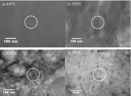
Figure 3- 15 Higher magnification cross sectional TEM images of coating area shown in Figure 3- 14-a) 450 oC sample, almost featureless; b) 550 oC sample, columnar grains; c) 650 oC sample, large polycrystalline grains; d) 750 oC sample, fine polycrystalline grains. (Circles show the area for SAD analysis showing in Figure 3- 21) [11]... 83 Figure 3- 16 Higher magnification TEM images of interface area shown in Figure 3- 14. a)
layer; d) 750 oC samples, almost no porous layer with diffused intermediate layer [11]... 84 Figure 3- 17 Locations of line scan of STEM-EDS analysis on cross section of calcium
phosphate coatings deposited at a) 450 oC; b) 550 oC; c) 650 oC; d) 750 oC [11]. ... 86 Figure 3- 18 Distribution of O, P Ca, Ti in the coating along the thickness measured by
STEM-EDS. a) 450 oC, b) 550 oC, c) 650 oC, d) 750 oC. [11]. ... 87 Figure 3- 19 Atomic Ca/P ratio of set temperature coatings throughout thickness evaluated by
STEM-EDS [11]. ... 91 Figure 3- 20 XRD results for set temperature coatings (comparison of those data to JCPDS
standard is presented in Table 3- 2) [11]. ... 92 Figure 3- 21 SAD pattern of set temperature coatings deposited at a) 450 oC; b) 550 oC; c)
750 oC; d) 750 oC. SAD detecting areas are marked with circles as showed in Figure 3- 15 [11]... 94 Figure 3- 22 FTIR results for set temperature coatings and HA target [11]... 96 Figure 3- 23 Optical micrographs of scratch test on coatings deposited at a) 450 oC; b) 550 oC;
c) 650 oC; d) 750 oC and related critical load in each case.[143] ... 99 Figure 3- 24 Schematic drawing of the cross section of calcium phosphate coatings deposited on heated Ti substrate (With increasing substrate temperature from 450 oC to 750
oC, thickness of porous layer is decreased and diffused intermediate layer is
formed in samples deposited at 650 oC and 750 oC) [143]... 105 Figure 3- 25 Schematic illustration of structural model for atomic intermixing HA
coating/titanium interface [107]. ... 105
Figure 4- 1 TEM images of cross section of coating-A, B, and C. (A-1,B-1,C-1 are images of cross section including both Ti and coating; A-2,B-2,C-2 are higher
magnification images of area showing interface and crystalline layer, and A-3,B-3,C-3 are highest magnification images of area showing interface layer) [151]120 Figure 4- 2 STEM images of cross sections of coating-A, B and C. (A-1,B-1,C-1 are images
A-2,B-2,C-Area of A1 ~ A6 labeled at coating in left column of images are areas measured
by STEM-EDS analysis)... 123
Figure 4- 3 XRD analysis of coating-A, B, C and pure Ti; index of peaks with comparison of standard JCPDS data are shown in Table 4- 3 [151]. ... 126
Figure 4- 4 FTIR analysis on coating-A, B and C [151] ... 127
Figure 4- 5 Atomic Ca/P ratio distribution throughout thickness of coating cross section measured by STEM-EDS. (Areas measured on the coating are labeled in the Figure 4- 2.) [151]... 128
Figure 4- 6 Atomic Ca/P ratio of coating outmost surface measured by XPS from top surface[151] ... 129
Figure 4- 7 AFM images of blank Ti and coating-A, B and C. ... 130
Figure 4- 8 Average Ra and Rq measured by AFM on coating-A, B, C and as polished Ti [151]... 130
Figure 4- 9 Optical images of pull off test area in sample A, B and C. (The labels EF, ED and CF represent epoxy failure, epoxy delamination, and coating coherent failure respectively [151]. ... 133
Figure 4- 10 Integrin activity reflective of binding locations between cell and material substrate [151] ... 135
Figure 4- 11 Average spreading area determined using Bioquant Image Analysis Software with area identified from Actin-FITC staining with HEPM cells after 24 hours of cell culture [151]... 135
Figure 4- 12 Fluorescent images on sample surfaces. DAPI-Nucleus (Blue), FITC-Actin (Green), TRITC-α6β4 Integrin (Orange-Red) [151] ... 136
Figure 5- 1 Picture of IBAD-2 ... 145
Figure 5- 2 Scheme of IBAD-2... 145
Figure 5- 3 Picture of 21 (top) and 133 (bottom) disc substrate cover plate ... 147
Figure 5- 5 Higher magnification TEM image of top layer of coating FGHA-Ag1 [156]... 158
Figure 5- 6 Higher magnification TEM image of bottom layer and interface of coating FGHA-Ag1. ... 158
Figure 5- 7 Higher magnification TEM image of transitional region between top layer and bottom layer of coating FGHA-Ag1 [156] ... 159
Figure 5- 8 TEM image of Ag particles shown in Figure 5- 7 [156]... 159
Figure 5- 9 STEM image of coating cross section area... 160
Figure 5- 10 Areas and grains in the coating cross section measured by STEM-EDS... 161
Figure 5- 11 Ag concentration of larger areas measured by STEM-EDS ... 161
Figure 5- 12 TEM (top) and STEM (bottom) image of cross section of coating FGHA-Ag2 [156]... 164
Figure 5- 13 TEM (top) and STEM (bottom) image of cross section of coating FGHA-Ag3 [156]... 165
Figure 5- 14 Higher magnification TEM images of top layer and bottom layer with interface of coating FGHA-Ag2 [156] ... 166
Figure 5- 15 Higher magnification TEM images of top layer and bottom layer with interface in coating FGHA-Ag3 [156]... 167
Figure 5- 16 XRD results of samples FGHA-Ag1, FGHA-Ag2, FGHA-Ag3 and FGHA (Ti peaks were removed for highlighting HA peaks) [156] ... 168
Figure 5- 17 Atomic Ca/P ratio evaluated by XPS and SEM-EDS on top surface of coatings [156]... 170
Figure 5- 18 Ag wt. % evaluated by XPS and SEM-EDS on top surface of coating [156].. 170
Figure 5- 19 Results of depth profiling measured by XPS, a) coating FGHA, b) coating FGHA-Ag1, c) coating FGHA-Ag2 and d) coating FGHA-Ag3 [156]... 172
Figure 5- 21 FTIR results of coating FGHA, FGHA-Ag1, FGHA-Ag2 and FGHA-Ag3 [156] ... 176 Figure 5- 22 Optical image of pull off area for coatings FGHA, FGHA-Ag1, FGHA-Ag2 and FGHA-Ag3 [156]... 178 Figure 5- 23 AFM image of coating FGHA, FGHA-Ag1, FGHA-Ag2 and FGHA-Ag3 .... 180 Figure 5- 24 Roughness measured by AFM [156]... 180 Figure 5- 25 Cumulative calcium release from samples over 24 hours incubation at 37 oC
[153]... 182 Figure 5- 26 Calcium release rate in mM per hour from samples incubated up to 24 hours at
37 oC[153] ... 182 Figure 5- 27 Cumulative calcium release from samples for 15 days incubation at 37 oC [153]
... 183 Figure 5- 28 Calcium release rate in mM per day from samples incubated up to 15 days at 37
oC [153]... 183
Figure 5- 29 Release of Ag+ ions from each of the Ag-doped FGHA coatings immersed in ultra super pure water over time.[153] ... 184 Figure 5- 30 Adherence of S. aureus Cowan I strain (ATCC 12598) to FGHA coating with
various amount of antibacterial agent Ag, FGHA coating without Ag, and blank Ti [153]. ... 185 Figure 5- 31 Normalized dsDNA to control titanium (blank) at each time point [153]. ... 186 Figure 5- 32 Total cellular and extracelllar protein over 8 days cell culture, average values of n=4 samples ± standard error of the mean [153]. ... 188 Figure 5- 33 Early apoptosis signal cyctochrome c normalized to dsDNA content over 8 days
cell culture, average values of n=4 samples ± standard error of the mean [153]. ... 188 Figure 5- 34 Late stage apoptosis effecter caspase 3 normalized to dsDNA content over 8
LIST OF TABLES
Table 2- 1 Lattice parameters of different apatite [2] ... 20
Table 2- 2 Mechanical properties of dense HA and hard tissue [9]... 21
Table 2- 3 Summary of physical and mechanical properties of unalloyed titanium [118]... 52
Table 2- 4 Mechanical properties of some titanium and its alloys compared to bone [118].. 53
Table 3- 1 Coating thickness and compositional analysis on Ti substrates measured by STEM-EDS [11] ... 82
Table 3- 2 Results of XRD and SAD for set temperature coatings [11]... 95
Table 3- 3 Bonding strength test results [143]... 97
Table 3- 4 Nano indentation test result [143] ... 100
Table 3- 5 Summary of features observed in calcium phosphate coating deposited on heated substrate [143]. ... 101
Table 4- 1 Summary of deposition temperatures for coating A, B and C [151]... 113
Table 4- 2 Summary of thickness of coating and layers, structures, and feature size ... 124
Table 4- 3 XRD index (hkl) of peaks shown in Figure 4- 3 with comparison of JCPDS [151] ... 126
Table 4- 4 Adhesion strength of coating A, B and C resulted from pull off test as well as their failure modes [151]... 132
Table 4- 5 Nano indentation results of Young’s modulus and nano-hardness [151]... 132
Table 5- 2 IBAD parameters for deposition of functionally graded calcium phosphates coatings with Ag ... 148 Table 5- 3 Summary of coating thickness and features of coating FGHA-Ag1, FGHA-Ag2
CHAPTER 1 INTRODUCTION
1.1 Hydroxyapatite (HA) coatings
Synthesized calcium phosphates (CaP), which are biocompatible [1-5] and bioactive [6-10], have been widely used as biomedical/bone implants. Hydroxyapatite (HA, [Ca10(PO4)6(OH)2]), one type of calcium phosphate, gains more attention due to its chemical
and crystallographic similarities to the inorganic components of natural bone and other hard tissue in mammals [9, 11]. Bone itself is a composite living material with both inorganic and organic phases. The inorganic phase, which is crystalline biological HA, comprises 60 to 70 percent of the bone tissue; water accounts for another 5 to 8 percent; and the organic phase, which is primarily collagen, accounts for the remaining portion [12]. Biological HA slightly differs with stoichiometric HA. Biological HA is a substituted apatite (Ca, M)10(PO4, Y)6(OH, X)2, where M represents metallic cations including Mg2+, Na+, K+, Sr+, or Ba+, etc; Y
represents chemical groups such as CO32-, H2PO4-, HPO42-, and SO42- etc; while X represents
F-, Cl-, and CO
32-, etc [9]. The plate-like biological HA crystals that make up the inorganic
as implants materials in dentistry or orthopedics such as dental implants, periodontal treatment, alveolar ridge augmentation, maxillofacial surgery and otolaryngology [26]. However, HA, due to its inherent characteristics of brittleness, poor tensile strength and low fracture, can only be used in none load bearing implants [9, 27].
Traditional load bearing implants are metallic materials such as Ti and its alloys, stainless steel and Co - Cr alloys that exhibit excellent mechanical strength and resistance to fracture. However, such materials lack bioactivity although they have relative good biocompatibility [28]. In order to take advantage of both the bioactivity of HA and the mechanical properties of metallic implants, HA coated metallic implants have been developed and primarily used in load bearing applications of dental and orthopedics. Compared to traditional uncoated implants, there are several advantages for using HA coated implants. First, HA coated implants, with bioactive surfaces, are able to allow direct bone growth on coating surface, and subsequently form biological fixation between bone and implants. The advantage of biological fixation compared to mechanical fixation of bioinert uncoated implants is that it is able to extend lifetime of the prosthesis by minimizing the micro movement between bone and implants as well as remaining functional. Secondly, with metallic implants completely covered by HA coating, the release of metallic ions into tissue as a result of corrosion in biological environment can be effectively prevented, avoiding the inflammatory reaction that is a cause of local pain and swelling of implants [29].
two years period follow up, there was a rapid bony integration of implants with bone apposition observed on the coating within six months, accompanied by specific patterns of bone remodeling. In addition, 97 % of the patients had a positive roentgenographic evidence of femoral ingrowth after two years [22]. Overall, applying HA coating on metallic implants enhances osteointegration and allows biological fixation, which prolongs the lifetime of prostheses.
1.2 Factors determining performance of HA coatings
As a medium between bone and implants, coatings have two primary functions: (1) to stimulate the osteointegration and bone ingrowth; (2) to transfer load between body and metallic implants. These functions require coatings to have both good bioactivity and mechanical properties.
expected in clinics since a short recovery time is preferred for patients whereas a strong fixation is important to survivability of implantation without loosening. However, the prerequisite for a successful implantation with a better lifetime is that coatings should be strong enough to survive under loading prior to the failure of biological fixation. Therefore, the good mechanical properties of coatings as well as the strong bonding between coating and substrate are necessary to guarantee coatings will not fail within the coating or delaminate from the substrate surface. Hence, in the viewpoint of the function of coatings, it can be classified as biological function (bioactivity) and mechanical function. Biological function determines the ability of osteointegration between bones and implants whereas mechanical function affects the ability of coating to transfer loading.
structure or large porosity increases the dissolution ability of HA because of the increase surface area or grain boundary area [31, 36]. In addition, the degree of similarities of HA coating with the biological bone in composition, microstructure, and mechanical properties determines the bioactivity of coating since the ingrowth and integration of bone are determined by the ability of coating to mimic the biological bone. Studies have shown that HA with atomic Ca/P ratio 1.67 in nanoscale structure, which is similar to biological bone, more readily promotes osteoblast and osteoclast cell activity than calcium phosphate with convention crystal structures [14, 24, 25]. The purity of HA also plays an important role on its bioactivity because the other phases presented in calcium phosphate may have different dissolution ability than HA. Those phases are usually diacalium phosphate [DCP, CaHPO4],
tricalcium phosphate [TCP, Ca3(PO4)2] and tetracalcium phosphate [TTCP, Ca4P2O9], which
are usually a result of the HA decomposition during processing of coating. It has been observed that the dissolution rate of calcium phosphate including HA is in the following order: ACP >> DCP > TTCP > TCP >> HA, where ACP represents amorphous HA and HA represents crystalline HA [31]. As we can see, these phases other than crystalline HA have higher dissolution ability than crystalline HA, and are favorable to coating bioactivity. For this reason, these phases have been also used to prepare the bioactive implants [37-39].
The adhesion strength of coating on substrate depends on the interface structure and coating thickness [31]. A atomic or chemical bonding is better than a mechanical bonding between coating and implant; a thinner coating is generally better than a thick coating due to a less residual stress existing at the interface after processing [40]. The crystallinity of coating influences the mechanical properties of coatings by their dissolution behavior or chemical stability of coating. For instance, a high dissolution ability of amorphous HA can result in coating loosing and the degradation of mechanical properties. In worst case, extreme dissolution on grain boundary or porosity of coating can eventually lead to the exposure of metallic implants in vivo. As a result, the toxic metal ions released to body due to corrosion could lead to an inflammatory effect or implantation failure. Therefore, it is important to optimize crystallinity, composition, and grain size of coating in order to control the mechanical properties of coating. It has been suggested that an ideal HA coating for orthopedic or dental implants would be the one with low porosity, strong cohesive strength, good adhesion to substrate, appropriate degree of crystallinity, and high chemical and phase stability [41, 42].
1.3 Problems associated with current HA coatings
disadvantages limiting these techniques although they have high deposition rate and low process cost. Hot isostatic pressing is able to improve the density of the coating by pressing on the coating during sintering; however, cracks were observed after sintering and the processing cost is high due to the encapsulations [57, 58]. Biomimetic deposition is able to form identical biological HA; however, low deposition rate leads to a high cost since it needs a process time of a few weeks [59, 60]. Sputtering deposition and pulsed laser deposition are able to deposit nanosacle and dense coating with relatively high deposition rate. In addition, they can increase the adhesion strength up to 30 MPa by the formation of diffusion layer at interface [61-65]. Ion dynamic mixed deposition and ion beam assisted deposition are able to further increase the adhesion strength to 40 ~ 50 MPa by the formation of atomic intermixed layer at interface [46, 66]. Although various techniques have been applied and coatings properties could be improved in some extent, as-deposited coatings processed by those techniques mostly are amorphous and not stable in vivo. A post deposition heat treatment at temperature mostly within 400 to 700 oC is necessary to crystallize coating; however, cracks, which form because of a mismatch of thermal expansion coefficients between coating and substrate, lead to poor adhesion strength.
failure due to inflammatory effect or coating delamination. In order to match the rate of bone growth around the implant as the coating dissolves, it is important to control the dissolution rate of the coating throughout the thickness. Besides, the process technique or parameters are supposed to be optimized in order to deposit a nanoscale HA coating with high density, adhesion strength, and cohesive strength. All these problems associated with current HA coatings urge us to develop a new coating that has good bioactivity, chemical stability, and good mechanical properties to achieve the initial quick fixation and long-term stability of prosthesis.
1.4 Functionally graded CaP/HA coatings processed by ion beam assisted
deposition with in situ heat treatment.
In order to achieve both the good bioactivity and the stability of coating, functionally graded Hydroxyapatite (FGHA) coating has been designed in this work. FGHA coating has a gradually decreased crystallinity/grain size from coating-substrate interface to coating top surface. The amorphous region near coating surface is expected to enhance cell growth by the high dissolution rate at the initial stage of implantation whereas the crystalline region near the interface between substrate and coating will allow coating to be stable, resulting in a strong biological fixation between bone and implants thereafter.
system that combines sputtering process with concurrent bombardment of secondary ion beam. It consists of two ion sources, a target, and a substrate in a vacuum chamber. The primary ion beam generated from primary ion source could have energy up to 2000 eV whereas secondary ion beam generated from secondary ion source is usually a few hundreds eV. During deposition, the primary ion beam is directed at the target surface to sputter the target materials. As a result, the individual coating atoms or molecules are created and subsequently condense and stick on the surface of the substrate as coating. At the same time, secondary beam is directed at the substrate surface to bombard the substrate or coating, modifying the properties of coatings. There are two modification effects due to bombardments:
1) At the beginning of deposition, the bombardment on the substrate surface helps atoms or moleculars of coating material penetrate into the substrate surface, creating an atomic intermixed layer at interface between coating and substrate. 2) The mobility of coating atoms increases, which helps coating particles to be
packed in a high density during deposition.
In order to control the crystalline gradient of the coating and minimize the negative effect of the post depositon heat treatment on the adhesion strength of the coating, in situ heat treatment on the substrate during deposition has been used in this work. Investigations have shown that coating’s crystallinity is primarily determined by the heat treatment temperature. The FGHA coatings will be processed with a gradually decreased substrate temperature from 450 to 750 oC during deposition in order to achieve the crystallinity gradient from interface to coating surface. In addition, the use of in situ heat treatment during deposition is able to minimize the residual stress caused by the mismatch of coefficient of thermal expansion between coating ans substrate, resulting higher adhesion strength. Finally, with in situ heat treatment, the processing time and cost can be effectively saved.
1.5 Functionally graded CaP/HA coatings with incorporated antimicrobials
infections are caused by aerobic cocci, most commonly S. aureus (23 %), and coagulase-negative staphylococci (25 %) [70].
The implant incorporated with antimicrobias is able to inhibit the infection by directly releasing antimicrobials. Ag has been used to cure infections for thousands years due to broad-spectrum antibacterial properties and it is, therefore, a good candidate for antimicrobial agents in HA coating [71]. However, Ag in small percentages is antibacterial while in large amounts can be toxic. Therefore, optimization of Ag concentration in the coating is necessary to guarantee good antibacterial effect without cytotoxicity effect. Most common technique to add Ag into the coatings is ion exchange method, in which the Ca ions in HA can be replaced by Ag ions when dipping the HA coatings into AgNO3 for a period
the one that can gradual release appropriate amount of according to infection chances over time. Therefore, controllable release of silver is important to prevent infection both in short-term and long-short-term efficiently.
In this work, we will dope Ag in entire thichness of functionally graded HA coating. The amorphous top layer of coating allows a higher release rate of silver due to its higher dissolution right after implantation; the crystalline layer maintains the silver as a reservoir, resulting in prevention of infection in long term. This can result in a more efficient prevention or infection control than conventional oral/intravenousantibiotics intake with less side effect. The coating will be processed by IBAD with in situ heat treatment; the dope of Ag into coating will be processed by co-sputtering of silver wires on HA targets together. In order to optimize the Ag concentration within the coating, a set of Ag-doped HA coating with different Ag concentration will be processed. The antibacterial effect and cytotoxicity of coating will be evaluated and the concentration of Ag in coatings will be optimized.
1.6 Objectives
atomic intermixed layer results in good bonding strength between the coating and substrate. The coatings will be processed by ion beam assisted deposition with in–situ heat treatment. The graded crystallinity from the interface to surface will be controlled by decreasing the substrate temperature during processing. Several advantages over the traditional uniform coating are expected with functionally graded coatings processed by IBAD. First, osteointegration is enhanced in early stages by the readily dissolved amorphous top layer and in later stages by bone in-growth in the crystalline bottom layer. Second, the coating bonds to the substrate on an atomic level as a result of atom intermixing of coating and substrate by the assist beam, which leads to better and more consistent adhesion strengths than plasma sprayed coatings [75]. Third, the HA coatings (less than 1 µm thickness) provide a higher interfacial strength and better fracture resistance than thicker plasma spray coatings. Moreover, the in situ heat treatment allows the growth of coatings with varying crystal structures without the need for post deposition annealing. Finally, tailored release rate of Ag associated with the variation of dissolution rate of the functionally graded coatings in the body is able to restrain the growth of bacterial associated with the implantation. With these advantages, following benefits for patients will be achieved.
1. Improved load bearing capacity of implants due to improved biological fixation as a result of better bone ingrowth into the coating surface
2. Extended lifetime of implants due to high adhesion strength of the coating to implant surface as well as better mechanical properties of the coating
4. Minimized infection chances both in short and long term due to incorporation of Ag into the entire thickness of coating and tailored release rate of Ag associated with the variation of dissolution rate of the functionally graded coatings in the body
5. Reduced production time and cost through in situ heat treatment
CHAPTER 2 LITERATURE REVIEW
2.1 HA
2.1.1 Chemistry of HA
2.1.1.1 Synthesized HA
Ca10(PO4)6(OH)2, the chemical formula of stoichiometric HA, denotes that the crystal
unit cell comprises two molecules of Ca5(PO4)3(OH)1 (exact chemical formula of HA) [9].
HA, along with fluorapatite [Ca10(PO4)6F2] and chlorapatite [Ca10(PO4)6Cl2], makes up the
apatite in nature [2]. It has a hexagonal structure with a P63/m space group [9]. Figure 2- 1
schematically shows its lattice. The arrangement of HA unit cell is characterized by a c-axis perpendicular to three equivalent a-axes which are at angle 120o to each other [9]. Ca2+, PO42-, and OH- groups are components of unit cell packed together in a hexagonal structure
[9]. There are two types of Ca atoms according to their position in unit cell. The four Ca atoms located in the octahedral site at three layers of hexagonal array with z = 0 and z = 0.5 and z = 1 are Ca I. The six Ca atoms located at the corners of the hexagonal column are Ca II; Like Ca I, Ca II atoms are not in the same plane and each three of them arrange in triangle positions at z = 0.25 and z = 0.75 [9]. Similar to six Ca II atoms, the six PO42- are in helical
Figure 2- 1 Schematic drawing of HA lattice [9].
2.1.1.2 Biological HA in natural bone
matrix. HA crystals are in the shape of needles or plates, and parallelled to and located between the collagen fibers, serving as the reinforcements to bone tissue due to its high hardness and stiffness [9] The size of HA crystals varies in different hard tissues. It is approximately 10 × 20 × 5 nm in mesenchymal hard tissues, whereas it is in 140 nm long and
80 nm wide in the enamel [2]. The ground substance are proteins, polysaccharides and polysaccharides, which act as cement, filling the space between collagen fibers and HA minerals [9].
Biological HA actually is a substituted apatite, and usually calcium deficient that means atomic ratio of Ca/P is lower than 1.67 of stoichiometric HA [9]. The appropriate formula of biological HA is given by
(Ca, M)10(PO4, Y)6(OH, X)2
where M represents metallic cations including Mg2+, Na+, K+, Sr+, or Ba+, etc; Y represents chemical groups such as CO32-, H2PO4-, HPO42-, and SO42-, etc; while X represents F-, Cl-,
and CO32-, etc. Substitution of Ca2+, PO43- or OH- by M, Y or X in the HA may cause changes
compared with F-free apatite is often used in teeth paste to prevent tooth decay by increasing the stability of apatite [9]. Different from F substitution, carbonate [CO32-] substitution
decreases in crystallinity and subsequently increases the dissolution of HA. Carbonate can substitute two sites of OH- site (Type A substitution) or PO43- site (Type B substitution); In
general, biological apatite is referred to as Type B [9]. Substitution of Mg2+, Na+, K+, Sr+, or Ba+ to Ca2+ can also impact to properties of apatite [9]. For instance, Mg2+ substitution can decrease in crystallinity and increase dissolution of synthetic apatite [9]
Table 2- 1 Lattice parameters of different apatite [2]
Materials a-axis c-axis
Human enamel HA 9.441 6.882
synthetic HA (non-aqueous) 9.441 6.882 synthetic HA (aqueous) 9.438 6.882 F-apatite (non-aqueous) 9.375 6.88
F-apatite (aqueous) 9.382 6.88 Cl-apatite (non-aqueous) 9.646 6.771
Cl,OH-apatite (aqueous) 9.515 6.858 CO3 apatite (non-aqueous) 9.544 6.859
2.1.2 Physical properties of HA
Physical properties of HA are primarily concerned with its application; particularly, tensile, compressive strength and fatigue resistance are the most important factors that have impact on the survivability of implants in load bearing application. Table 2- 2 shows the comparison of physical and mechanical properties of HA to hard tissue [9]. HA has the tensile strength of 38 ~ 300 MPa and the bending strength of 38 ~ 250 MPa, which are comparable to those of hard tissues in body [9]. The Young’s modulus is 35 ~ 120 GPa, higher than the 10 ~ 20 GPa of hard bone tissue. Even though the most of the properties of HA are comparable to those of hard tissues, bulk HA can not be used to load bearing application or large size implants due to its low fracture toughness [9]. It has been reported that the most of the loaded dental HA implants were broken within one year [9]. Therefore, HA is suggested to be used in non or small load bearing implants [26].
Table 2- 2 Mechanical properties of dense HA and hard tissue [9] Items
Properties Dense HA Hard tissue (Bone) Young’s modulus (GPa) 35-120 10-20
The mechanical properties of HA vary with the porosity, grain size and impurities of HA. With a maximum microporosity of 5 vol. % and the pore size less than 1 µm in diameter, dense HA has 38 ~ 300 MPa of tensile strength [26]. The porosity and various pore sizes are resulted from the processing of HA. For example, sintered HA prepared by sintering HA powders at 1000 ~ 1500 oC has various porosities less than 0.5 and pore size from a few hundreds nm to a few hundreds µm depending on processing parameters such as different pressure applied during sintering [26]. The impact of porosity and pore size on mechanical properties have been established [26]. The compressive strength of sintering HA is given by
p V c 5 exp 700 − = σ
where σc is compressive strength in MPa,
p
V is total pore volume fraction ranging 0 ~ 0.5.
The tensile strength of sintering HA is given by
m V t 20 exp 220 − = σ
where σtis tensile strength in MPa,
m
V is the volume fraction of micro porosity [26].
2.1.3 Applications of HA
Figure 2- 2 HA coated dental screw (top) [77] and femoral stem of total hip replacement (bottom) [78]
2.1.4 Mechanisms of bone growth on HA coatings
Biological fixation of bone to HA coated implants is a process of coating dissolution accompanied by the formation of new bone in the gap between implant surface and existing bone [31]. The process is shown in Figure 2- 3 and can be discribled as followings [31]. (i) Partial dissolutions of HA coating where calcium and phosphate ions are released from
the coating, causing a rise of the calcium and phosphate ion concentration in the local environment around the coating
(ii) Precipitations of HA crystals on coating surface and subsequently the exchange of various ions between new formed HA crystals and surrounding tissues
(iii) Formations of carbonated HA layer of microcrystals and macrocrystals with the incorporation of collageneous matrix, as well as bone growth toward the implant
(iv) Bone remodelings in the area of stress transfer: osteoclasts resorb normal bone by actively secreting hydrogen ions into the extracellular space, creating a local pH of approximately 4.8, and leading to fast resorption of both carbonated HA in bone mineral and HA coating
(v) Further ingrowth and remodeling of bone at bone-implant interface, and the formation of biological fixation as a result of the bidirectional growth of a bonding layer
2.1.5 Impacts of HA’s properties on its performance
HA coated implants are designed to be implanted in body to replace or restore the function of tissue that will be replaced. Implantation involves the contact of tissue to the implants and eventually the growth and integration of tissue on the implants. Therefore, the implants are firstly required to be biocompatible and bioactive without repulsive effect. Secondly, the implants must be able to perform the functions of the replaced tissue, which requires the implants to be designed with functional properties. Thirdly, the implants are expected to have both good mechanical and chemical stability to guarantee the survivability of implantation in the long term. Good mechanical properties enable a better lifetime of implants under loading whereas stable chemical properties are able to minimize the release of toxic ions or particles from implants to tissue and therefore minimize the adverse effect such as inflammation. All these expected functions can be influenced by physical and chemical properties of HA such as its composition, microstructure, dissolution ability, coating thickness, bonding between the coating and substrate.
mechanical properties due to mass loss from implants surface; the worst case could be the exposure of substrate to biological environment, subsequently the release of the ions, atoms, or particles from metallic substrate in body, and eventually an adverse response by tissues [81, 82]. Therefore, HA with relative low crystallinity has the best biological property. Grain size also has impact on the stability of HA. In general, grain boundary is the place where corrosion starts. HA consisting of fine grain size has lager grain boundary area and is less stable than HA consisting of large grain size.
Besides microstructure, macrostructure also has influences on the properties of HA. Porous HA has a larger total surface area and can release more ions; therefore porous HA is more dissolvable and favored to new bone formation than dense HA. In addition, porous structure is able to greatly improve the bonding strength of new bone on the implants since the porous structure allows bone ingrowth and therefore enhance strength of tissue attachment to implants. In general, the pore size can be nano scale to a few hundreds of µm. However, the large surface area and high dissolution rate of porous structure HA could impair its mechanical properties. Particularly, debris detached from implants will cause adverse effect in body.
the mechanical properties of coating as well as the bonding between coating and implants srong are good enough to transfer load from the implant to the surrounding bone properly.
The degree of achievement of these functions depends on the ability of implants to mimic the natural properties of bone [23, 83, 84]. Synthesized HA has its nominal composition [Ca10(PO4)6(OH)2], which is similar to biological HA (Ca, M)10(PO4, Y)6(OH, X)2. Numerous literatures that study the synthesis of substituted HA such as F- and CO3
2-substituted HA to mimic exact composition of biological bone have been published. It has been reported that HA with F- substitution for the OH- group can improve its physical, chemical and biological properties because F aids in the crystallization of amorphous HA and shows a higher corrosion resistance in biological environment [85, 86]. HA with CO3
2-substitution for PO43- can decrease the a axis due to the smaller planar CO32- group
substitution of larger tetrahedral group and increase the c axis of HA lattice; this so called B type carbonated HA has reduced crystallinity, size of the precipitates and durability of tooth enamel and bones against weak acids [87]. Besides, synthesized HA is usually not pure HA due to processing. The main impurities various calcium phosphate compunds including amorphous HA and β-TCP showing higher dissolution rate than pure crystalline HA, have
2.2 Processing of HA
2.2.1 Synthesis of HA powders
HA powders are the raw materials for the preparation of bulk HA or HA coating. Pure HA powders can be obtained from precipitation methods, hydrolysis method, calcium phosphate reagent, solid-state reactions, and hydrothermal reactions.
Precipitation is the commercial method for the preparation of HA powders. There are two precipitation methods. The first is Rathje’s method in which phosphoric acid [H3PO4] is
added into a stirring suspension of calcium hydroxide [Ca(OH)2] in water. The second is
Hayek and Newesely’s method by which calcium nitrate [Ca(NO3)2] and ammonium
phosphate [(NH4)2HPO4] react with added NH4OH. The reaction equation of these two
method are shown below [55].
10 Ca(OH)2+ 6H3PO4Æ Ca10(PO4)6(OH)2+18H2O EQ- 1
10 Ca(NO3)2+6(NH4)2HPO4+2 NH4OHÆ Ca10(PO4)6(OH)2+14NH3+10H2O+20NO2 EQ- 2
Hydrolysis is a method that prepares HA by hydrolysis of acid calcium phosphate such as dicalcium phosphate dehydrate [DCPD, CaHPO4•2H2O], octacalcium phosphate [OCP,
Ca8H2(PO4)6•5H2O], or dicalcium phosphate [DCP, CaHPO4] in ammonium, sodium, or
potassium hydroxide at temperature below 100 oC [79]. HA processed hydrolysis is also calcium deficient.
Calcium phosphate reagent uses the commercially available calcium phosphate powder as the reagent with or without the addition of appropriate amounts of CaCO3 or Ca(OH)2 or
CaO to make the apatite [79]. This method can partially overcome the problem of calcium-deficient and thus minimize the formation of β-TCP phases upon sintering.
Solid-state reactions is a method by which calcium compounds of either CaHPO4 or
Ca3(PO4)2 with Ca(OH)2 are mixed, compressed and sintered above 950 oC [79]. The
reactions are given below [79]:
6CaHPO4+4Ca(OH)2ÆCa10(PO4)6(OH)2+6H2O EQ- 3
3Ca3(PO4)2+Ca(OH)2ÆCa10(PO4)6(OH)2 EQ- 4
Hydrothermal reactions carry out the reactions shown in EQ-3 or EQ-4 hydrothermally at 275 oC under steam pressure of 12000 psi. β-TCP, Ca3(PO4)2 and tetracalcium phosphate
TTCP, Ca4P2O9, Ca4(PO4)2O can be easily converted to HA hydrothermally under these
2.2.2 Processing of dense HA
Dense HA can be used as raw materials for HA coating or carved as biomedical bone implants [26].
Conventional sintering method is a method that prepares dense HA by compacting and sintering of HA powders. HA powders are firstly compacted with binder into a mold with pressure 60 to 80 MPa in order to form a green body. The green body is then sintered in air at the temperature usually 950 to 1300 oC for several hours, with both the heating and cooling rate of 100 oC/hour [79]. The properties of powders and charcteristics of sintering process such as the temperature and duration of sintering unavoidably result in a small percentage of porosity [79]. Generally, HA with porosity less than 5 vol. % is considered as dense HA [79].
2.2.3 Processing of HA coatings
2.2.3.1 Plasma spraying
Plasma spraying is currently the commercial technique for coating HA on metallic implants [2, 5, 31, 35, 36, 40, 43-45]. It is a process in which HA powders are melted or partially melted by high temperature plasma, and then sprayed onto substrate surface to solidify as coating [2]. Figure 2- 4 shows a schematic drawing of plasma spraying. HA powders with diameter of few µm are carried by noble gas and injected into plasma flame where temperature can be 10000 ~ 30000 oC and HA powders are rapidly heated and accelerated to a high velocity towards the substrate surface, followed by rapid cooling [2]. High deposition rate and low cost are the most significant advantages of plasma spraying [2]. In addition, the facility is easy to operate and maintain due to less controllable parameters when compared to other techniques. The typical thickness of plasma sprayed HA coating ranges from 70 ~ 120 µm, which can be finished within a few minutes [2].
Figure 2- 4 Scheme of plasma spraying process [91]
2.2.3.2 Dip coating
screws were observed higher than that for uncoated screws (249 vs. 133 N·cm) at 4 months after impanation [56]. It has been also observed that implanted areas for HA coated screws were denser and provided better bonding [56]. Over all, the advantage of dipping method is its high deposition rate at low cost and ability to coat complex structure. However, the mismatch of coefficient of thermal expansion is a problem resulting in the micro cracks in coating after sintering, which decreases the bonding strength between substrate and coating.
2.2.3.3 Sol-Gel
Sol-Gel deposition is a process in which implants are processed by dip-coating or spin-coating using sol or sol-gel of HA, followed by sintering [18, 48-51]. Sol-gel method offers a molecular-level mixture of calcium and phosphorus precursors. In an investigation of HA coatings on alumina substrates processed by a sol-gel method using ethanol solution of Ca(NO3)2 • 4H2O and P2O5 as a dipping source, it was observed that the HA coating
obtained at 500 oC has good crystallinity, dense morphology and adhesion strength of 10 MPa [18]. The coating obtained at 750 oC also has good crystallinity and adhesion strength
2.2.3.4 Electrophoretic deposition
Figure 2- 7 Schematic drawing of electrophoreses cell for membrane method [52].
2.2.3.5 Biomimetic coating
Biomimetic coating is a process in which a biologically active HA coating is formed on a substrate after immersion in a simulated body fluid with a supersaturated calcium and phosphorous solution at pH=7.4 and temperature 37 oC for a while. The deposition is based on the heterogeneous nucleation of calcium phosphate from SBF with very low deposition rate; it normally requires an immersion period of about 14 ~ 28 days with frequent replenishment of SBF solution to have substrate completely covered by HA [60]. As deposited biomimetic coating was poorly crystallized and the composition of coating depended on the Ca/P ratio of SBF [59, 60]. The advantage of biomimetic deposition is low process temperature and incorporation of bone growth simulating factors whereas the disadvantage of this method is its low deposition rate. The concentrated SBF has been used and proved to be able to increase the deposition rate [60, 93].
2.2.3.6 Hot isostatic pressing
The bonding strength measured via four-point bend test was 62 MPa between the coating and Ti substrate for the sample processed using HIP for 35 min at 700 ~ 850 oC and pressure of 100 mbar; the high bonding strength was attributed to the reaction and diffusion between coating and Ti substrate at increased pressure and temperature [58].
2.2.3.7 Pulse laser deposition
Pulse laser deposition (PLD) is a process in HA coating are deposited onto substrate by a high power pulsed laser beam to striking (laser ablation) and evaporating HA target surface. [94-100]. Figure 2- 10 schematically showsa pulsed laser deposition system. The coating is dense or porous with thickness of 0.05 ~ 5 µm and has various crystallinities depending on process parameters. However, the formation of other calcium phosphate compunds has been observed due to the decomposition or preferential ablation during deposition [101]. The in situ heat treatment of substrate [95, 96, 98-100] and the water vapor [95-100] in chamber have been unutilized in PLD to help the formation of crystalline HA during deposition. Investigation has shown that the minimum temperature of in situ heat treatment to crystallize coating is 450 oC without the presence of water vapor whereas the temperature can be decreased to as low as 300 oC with the high partial pressure of water vapor [96].
Figure 2- 9 SEM image of cross section of HA-coated Ti after HIP at 850 oC and 1000 bar [58]
2.2.3.8 Sputtering deposition
Sputtering deposition is a process by which atoms or molecules of a target material are ejected under bombardment of high-energy particles/atoms generated from ion sources and subsequently condensed on a substrate as a thin coating [61-65]. Figure 2- 11 shows the schematic drawing of the sputtering deposition. Sputtering deposition compromises these steps [104]:
1) Generation of ions at ion sources and direction of ions at a target material 2) Ejection of atoms from target materials under bombardment of ions
3) Transportation of atoms to the substrate surface through a region of reduced pressure 4) Condensation of atoms on the substrate, forming a thin coating
The high-energy particles used in sputter-deposition are generated by glow discharge that is a self-sustaining type of plasma. The plasma is usually generated by creating free electrons within the discharge region when applying a DC or RF field to a pressurized gas such as argon. Sputtering yield (the number of atoms ejected per incident ion) is because higher yield can result in higher deposition rate. Three factors listed as follow can affect deposition rate via affecting sputtering yield [104].
1) Target material
2) Mass of the bombarding particles 3) Energy of bombarding particles
adhesion strength of HA coating processed by sputtering could be more than 30 MPa. It was reported that the coating processed by sputtering are uniform and dense with thickness of 0.5 ~ 3 µm [1]. However, sputter deposited HA coating is amorphous and needs a post deposition heat treatment at 450 ~ 750 oC to be crystallized, which could result in serious residual stresses and reduction of bonding strength. Figure 2- 12 shows the representative surface morphology of sputtered CaP coatings on glass substrate. The as sputtered CaP coating was dense and amorphous and its surface consisted of 100–200 nm particles (A). Coating after heat treatment for 1 hour at 400 oC exhibits similar particle size and clear crystal boundaries (B). With increasing of heat treatment to 4 hours, the spalling of CaP coatings was observed (C).
2.2.3.9 Dynamic mixing deposition
Dynamic mixing technology is a process that can improve the adherence of coating to substrate due to the formation of a continuous gradient Ti-Ca-HA layer at the interface resulted from bombardment of assisted beam with energy up to hundreds of keV [46, 66, 106]. Ion beam dynamic mixing deposition system usually consists of one primary evaporation source and one assisted ion source as shown in Figure 2- 13 [66]. Similar to sputtering deposition, the atoms or molecules evaporated from target source condense on the surface of the substrate, the assisted ion beam simultaneously irradiates the substrate with high energy ions [46, 66]. However, high assisted beam energy can result in low deposition rate and impurities in coating due to preferential resputtering. In addition, as deposited coating is amorphous and needs post deposition heat treatments. The bonding strength of coating after heat treatment at 600 oC for 1 hour was 41.7 MPa [46].
2.2.3.10 Ion beam assisted deposition
In order to improve the coating properties such as bonding strength and density, ion beam assisted deposition (IBAD) has been applied to prepare HA coatings [3, 4, 38, 39, 67, 107-116]. IBAD usually consists of two sources; one is for sputtering (primary ion source) or evaporating (electron source) target materials whereas the other is for bombarding (secondary ion sources) the substrate surface to modify the coating properties during deposition.
Figure 2- 14 shows the schematic of IBAD system that consists of two ion sources. This system is also called dual ion beam (DIB) system since both beams are ion beams. The IBAD process of HA coating can be described as follows. Under the sputtering of primary beam, ions or molecules of target materials are removed from target surface and directed towards the substrate surface to deposit coating. At the same time, the energetic ions of secondary beam bombard substrate surface and increase the mobility of coating particles. As a result, coating particles penetrate into the substrate surface at the beginning of deposition, resulting in atomic intermixed layer that is atomic bonding. In addition, with further deposition, coating parilces are packed in high density, resulting better mechanical properties.
rate. Particularly, the secondary beam voltage and current have key impacts on coating properties. Therefore, there are 4 parameters available to adjust separately to refine the coating properties.
As for coating properties, IBAD processed coatings have atomic bonding between coating and substrate, which results in superior adhesion strength than mechanical bonding processed by plasma spraying. The substrate surface condition prior to deposition is another difference between IBAD and plasma spraying. Substrate samples used for IBAD are being polished to mirror surface in order to facilitate formation of atomic intermixed layer, instead of rough surface in plasma sprayed coatings. In addition, coatings processed by IBAD are dense and amorphous. The dense structure is resulted from the compaction of particles in atomic or molecular level on substrate surface by the secondary beam whereas the amorphous structure is resulted from the deposition at room temperature and post heat treatment is needed to crystallize coating to improve its crystallinity and chemical stability. Low coating thickness is also an important characteristic of coating processed by IBAD resulted from the deposition rate as low as a few nanometers per minutes.
2.2.3.11 Ti and Ti alloy substrate materials
on surface [29]. The mildly cold-worked Ti CP is a typical CP Ti and its microstructure is single-phase α-Ti grains with the grain size varying from 10 to 150 µm depending on processing conditions [28]. Titanium alloys, on the other hand, are named by their composition. Ti-6Al-4V, which contains 6 wt. % Al and 4 wt. % V, is the α + β alloy. It has been the most widely used titanium alloy because of its good mechanical properties. Different from CP Ti, Ti-6Al-4V consists of 90 vol. % of α-Ti and 10 vol. % of β-Ti [28]. Table 2- 3 and Table 2- 4 show the physical properties of Ti and its alloys.
Table 2- 3 Summary of physical and mechanical properties of unalloyed titanium [118]
Property Value
Atomic number 22
Atomic weight (g/mol) 47.9
c (Å) 4.6832 ± 0.0004
α, hexagonal, closely packed
a (Å) 2.9504 ± 0.0004
Crystal structure
β. Cubic. Body centered a (Å) 3.28 ± 0.003
Density (g/cm-3) 4.54
Coefficient of thermal expansion, α, at 20 oC (K-1) 8.4 × 10⁻⁶
Thermal conductivity (W/ (m•K) 19.2
Melting temperature (oC) 1668
Boiling temperature (oC) 3260
Transformation temperature (oC) 882.5
Electrical resistivity- high purity (µΩcm) 42
Electrical resistivity -Commercial purity (µΩcm) 55
Modulus of elasticity, α, (MPa) 105
Yield Strength, α, (MPa) 692
Table 2- 4 Mechanical properties of some titanium and its alloys compared to bone [118]
Alloy designation Microstructure Elastic modulus E (GPa) Yield Strength YS (MPa) Ultimate strength UTS (MPa)
cpTi α 105 692 785
Ti-6Al-4V α/β 110 850 ~ 900 960 ~ 970
Ti-6Al-7Nb (protasul-100) α/β 105 921 1024
Ti-5Al-2.5Fe α/β 110 914 1033
Ti-12Mo-6Zr-2Fe (TMZF) Metastable β 74 ~ 85 1000 ~ 1060 1060 ~ 1100
Metastable β 82 771 812
Ti-15Mo-5Zr-3Al
Aged β+α 100 1215 1310
Ti-0/20Zr-0/20Sn-4/8Nb-
2/4Ta-(Pd, N, O) α/β N/A 726 ~ 990 750 ~ 1200
Ti-Zr Cast α’/β N/A N/A 900
Ti-13Nb-13Zr α’/β 79 900 1030
Ti-15Mo-3Nb-0.3O
(21SRx) Metastable +silicides β 82 1020 1020
Ti-35Nb-5Ta-7Zr (TNZT) Metastable β 55 530 590 Ti-35Nb-5Ta-7Zr-0.4O
(TNZTO) Metastable β 66 976 1010
2.3 Functionally grade HA/CaP coatings
Traditional HA coatings have uniform crystallinity, which cannot satisfy both the bioactivity and chemical stability at the same time. Investigations have revealed that the amorphous HA is able to promote osteointegration because it is more dissolvable than crystalline HA and therefore can release more Ca and P ions. However, the fast dissolution of amorphous HA can lead to coating loss quickly and subsequently the exposure of metallic implants in vivo. In this case metallic ions could be released into the body due to corrosion, which inhibits the apatite formation [119].
Figure 2- 15 Cross section of functionally graded HA coating on Si [121]
2.4 HA/CaP coatings with antimicrobials
Investigations have shown that infections are primary problems associated with biomedical implantation [68]. The presence of biomedical implants inside the body interferes with host defense mechanism, leading to a foreign body reaction [68]. The foreign body reaction seems to be induced by continuous chemical or mechanical stimuli arising from biomaterial implants [68]. Recently, the HA incorporated with Ag/Ag+ [69, 71, 73, 74, 123-138], Cu2+ / Zn2+ [74, 137], ampicillin [139], and doxycycline [129] have been studied for preventing the infections. The antimicrobials are expected to release gradually in local region to inhibit the bacterial in short or long term. Among these antimicrobials, Ag/Ag+ has broad strong inhibitory and bactericidal effects as well as a broad spectrum of antimicrobial activities [126].
Mostly Amorphous Layer
Nano-grain structure
2.4.1 Mechanisms of antibacterial effect of Ag/Ag+
It was generally believed that heavy metals react with proteins by combining the SH groups, which leads to the inactivation of proteins [126, 130]. In an investigation of the inhibition mechanism of silver ions on microorganisms such as Gram-negative Escherichia coli (E. coli) and Gram-positive staphylococcus aureus (S. aureus), it implies that the released silver ions penetrate the bacterial cell wall and enter into the cells, subsequently turn DNA into a condensed form as a reaction against the denaturation [126]. At the same time silver ions reacts with proteins [126]. As a result, DNAs of bacterial lose their replication ability and proteins of bacterial become inactivated, which leads to the damage and even the death of microorganisms [126].
2.4.2 Processing methods of doping Ag/Ag+ in coating
2.4.2.1 Ion exchange method
So far, the mostly common method for incorporating the Ag+ in HA coatings is ion exchange method by which HA is immersed into Ag+ solution such as AgNO
3 for a while to
exchange sliver ions in solution with Ca2+ in coating surface, producing Ag substituted HA [69].
2.4.2.2 Sol-Gel route
Sol-Gel route is a method in which Ag-doped HA sol is produced by mixing the HA sol with AgNO3 powders, followed by coating on passiavated Ti surface by spin coating at 5000
2.4.2.3 Thermal or cold spraying
Thermal spraying has been used to deposit Ag-doped coatings [140]. This method uses HA and Ag2O powder as raw materials. Coating was deposited on Ti at flame temperature
2700 oC and it was found that Ag concentration in the coating was 0.3 wt. % and coating was
mostly amorphous. The reduction of Ag amount in the coatings compared to in the raw materials has been attributed to the deposition temperature of 2700 oC that can evaporate Ag [140]. In addition to thermal spraying, cold spraying has been also used to deposit Ag-doped coatings [141]. This method uses 5 % doped Ag-HA powder and PEEK (poly-ether-ether-ketone) powder as raw materials. The composite coating was deposited at temperature of 150 ~ 160 oC in order to avoid the decomposition of PEEK. It has been observed that the amount of Ag in coating can be adjusted with controlling the proportion of Ag-doped HA powder to PEEK powders [141].
2.4.2.4 Sputtering deposition
2.4.3 Antibacterial effects and cytotoxicity of Ag-doped HA
Although silver has antibacterial effect, it is toxic if Ag concentration in coating is too high. It is necessary to establish the threshold of Ag % in coatings in order to optimize the antibacterial effects and cytotoxicity. However, there is discrepancy for optimum concentration due to the different doping methods and biological test methods.
culture [73]. In addition, no significant difference in the in vitro cytotoxicity was observed between HA and Ag doped HA coating surface when using human embryonic palatal mesenchymal cells (HEPM) after 24 hours incubation [73].
Ag-doped coating has been also processed by ion exchange method in which HA coating prepared by IBAD was immersed in a 20 ppm AgNO3 solution to carry out ion
exchange between Ag+ and Ca2+ in HA coating [71]. In this case, the samples treated with 20
ppm AgNO3 solution showed obvious antimicrobial effect against Escherichia coli, Pseudomonas aeruginosa, Staphylococcus aureus, and Staphylococcus epidermidis compared to untreated samples. The minimum inhibitory concentration of AgNO3 was
measured to be 1.302 µg/ml. The amount of silver ions released in simulated body fluid (SBF) solution is a function of time, in which at first the level of silver ions released from the coating in SBF solution increases quickly with time, but after 24 hours, the silver concentration reaches a constant level [71]. In addition, it was also found that the compounds in coating were Ag-substituted HA and AgCaP [71]. Investigations were performed to evaluate the cytotoxicity of Ag-doped coating processed by ion exchange method by using murine macrophages, cell line RAW264.7 and osteoblasts, MG63 [130]. The results indicated that the number of macrophages in coating treated with up to 20 ppm AgNO3 solution was not significantly reduced when compared to coating without Ag,
~ 15 at. % of Ag ions in coating surface expressed bactericidic and cytotoxicity by action whereas 5 at. % samples did not suppress growth of bacterial and render toxic action on cells. The 7 at. % samples showed a rather optimum ratio of antibacterial effect and cytotoxicity [133].
Investigation has also shown that the gradual release of Ag/Ag+ is important in order to keep an effective concentration of antimicrobial to inhibit the bacterial. The slow release of Ag+ from Ag-doped micro porous HA coating in vitro was conducted to evaluate the release behavior of Ag+ in SBF. The results show that the release rate of Ag+ from Ag-HA coating containing 6000 ppm Ag+ in SBF was initially high at the first day and gradually decreased until the end of the experiment at day 7 [69]. Approximately 50 % of Ag ions were released within the first 24 hours [69].
![Figure 2- 1 Schematic drawing of HA lattice [9].](https://thumb-us.123doks.com/thumbv2/123dok_us/1656462.1207736/35.612.142.489.71.373/figure-schematic-drawing-ha-lattice.webp)
![Table 2- 1 Lattice parameters of different apatite [2]](https://thumb-us.123doks.com/thumbv2/123dok_us/1656462.1207736/37.612.113.522.351.589/table-lattice-parameters-different-apatite.webp)


![Table 3- 1 Coating thickness and compositional analysis on Ti substrates measured by STEM-EDS [11]](https://thumb-us.123doks.com/thumbv2/123dok_us/1656462.1207736/99.612.96.543.108.381/table-coating-thickness-compositional-analysis-substrates-measured-stem.webp)
![Figure 3- 16 Higher magnification TEM images of interface area shown in Figure 3- 14. a) 450 olayer with diffused intermediate layer [11]](https://thumb-us.123doks.com/thumbv2/123dok_us/1656462.1207736/101.612.62.564.104.457/figure-higher-magnification-images-interface-figure-diffused-intermediate.webp)
![Figure 3- 17 Locations of line scan of STEM-EDS analysis on cross section of calcium phosphate coatings deposited at a) 450 oC; b) 550 oC; c) 650 oC; d) 750 oC [11]](https://thumb-us.123doks.com/thumbv2/123dok_us/1656462.1207736/103.612.86.547.89.443/figure-locations-analysis-section-calcium-phosphate-coatings-deposited.webp)
![Figure 3- 19 Atomic Ca/P ratio of set temperature coatings throughout thickness evaluated by STEM-EDS [11]](https://thumb-us.123doks.com/thumbv2/123dok_us/1656462.1207736/108.612.126.504.72.357/figure-atomic-ratio-temperature-coatings-thickness-evaluated-stem.webp)
