ISSN: 2319-8753
International Journal of Innovative Research in Science,
Engineering and Technology
(An ISO 3297: 2007 Certified Organization)
Vol. 3, Issue 7, July 2014
Casting Defect Analysis and Optimization
Using Computer Aided Casting Simulation
Technique
Sandeep.v. Chavan
1, Rajeev.K.Tavildar
2M.Tech Student, Department of Mechanical Engineering, KLS’ GIT, Belgaum, Karnataka, India 1
Assistant Professor, Department of Mechanical Engineering, KLS’ GIT, Belgaum, Karnataka, India 2
ABSTRACT:
The casting defect analysis and optimization using computer aided casting simulation technique plays
vital role in manufacturing of metal parts and determining various casting defects. In pressure die casting, we require a quality die to prevent unfilled phenomena, weld lines, deflection and air traps and provide two overflows for filling thin section of existing part. The gating system is very critical to a die-casting die, but designing the gating system is an iterative process that can be very time-consuming and costly. The aim of this work is, (a) to identifying the best gate location for the component taking into consideration the flow balance and to avoid differential Clamp force and pressure, (b) to optimize the model of gate location, (c) Study the causality of the defects arrive and their solutions, (d) commenting on simulation results and selecting best suitable gate design for manufacturing the final part and (e) to validate the proposed approach.KEYWORDS:Casting defects; Pressure die casting; CAE; Gating system; Overflow; Casting simulation; Aluminium alloy
I. INTRODUCTION
Metal castings are fundamental building blocks, the three-dimensional integral shapes indispensable to practically all other manufacturing industries and casting is one of the oldest manufacturing processes, dates back to 3000B.C.Although the manufacturing path from the liquid to the finished shape is the most direct one, this directness involves the greatest difficulty. This is because of the number of parameters needed to be controlled simultaneously; melting, alloying, moulding, pouring, solidification, finishing, etc. Each of these aspects has to be correct since failure of any single one could probably cause the casting to fail [1].
The versatility of metal casting is demonstrated by the number of casting and molding processes currently available.
This wide range of choices offers design engineers and component user’s enormous flexibility in their metal forming
needs. Each process offers distinct advantages and benefits when matched with the proper alloy and applications.
II. TYPES OF CASTING TECHNIQUES AND GATING SYSTEM
Figure.1.Gating system
2.1 Casting defects: Foundry industries in developing countries suffer from poor quality and productivity due to involvement of number of process parameters in casting process. Even in a completely controlled process, defects in casting are observed and hence casting process is also known as process of uncertainty which challenges explanation about the cause of casting defects [7]. Defects found in castings may be divided in to three classes
a. Defects which can be noticed on visual examination or measurement of the casting.
b. Defects which exists under surface and are revealed by machining, sectioning or radiography.
c. Material defects discovered by mechanical testing (tensile, bending, impact, etc) of the casting.
Some defects are common to any and all casting processes are misrun, cold shut, cold shot, hot tear, porosity etc
III. METHODOLOGY
3.1 Guidelines for processing
Fill time: The casting should have enough space on the parting line for the gate and vents. The gate length is the gate area divided by the gate thickness. The gate area depends on selected die cavity fill time and gate velocity. Die cavity fill time is selected on the grounds of, i) Thinnest casting wall thickness, ii) Thermal properties of casting alloy and die material,
iii) Combined volume of the casting and overflows and iv) Percentage solidified metal allowed during filling.
Gate area: Total gate area is calculated with the cavity fill time, gate velocity and total casting + overflows volume according to the following equation.
Gate velocity: Possible gate thickness range depends on the selected gate velocity (or vice versa) according to the following equation.
(3)
3.2 Casting simulation for casting defect analysis
Simulation is the process of imitating a real phenomenon using a set of mathematical equations implemented in a computer program. In casting simulation the mould filling and solidification analysis is done to identify the hot spots
{ } (1)
ISSN: 2319-8753
International Journal of Innovative Research in Science,
Engineering and Technology
(An ISO 3297: 2007 Certified Organization)
Vol. 3, Issue 7, July 2014
TABLE 1: Casing simulation and optimisation methodology
STEP 1: Data Gathering Part model, Material, Process parameters, Methods design, Existing defects
STEP 2: Methods Design Parting line, Cores, Feeders, Gating system, mold cavity layout
STEP 3: Simulation Model import, Mesh generation, Material and process, Visualization
STEP 4: Optimization Modify design, Simulation, Check quality,
STEP 5: Project Closure Methods report, Analysis report, Compare results, Archive project
IV. FINITE ELEMENT ANALYSIS
4.1 Data collection:
In this stage for selected casting the data regarding the, process parameters, materials, methods design is collected and analysed. The following table 2 details the process parameters and material used for the processing.
TABLE: 2 Process parameters
Material Aluminium alloy -1100
Die temperature 288oC
Melting temperature 643oC
Density 2712 Kg/m3
Fill time 0.075sec
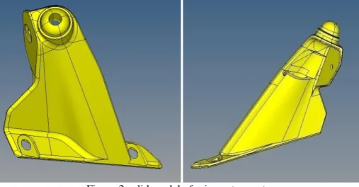
4.1 CAD model design:
Input to the simulation program is the 3D solid CAD model of the casting in STEP format, so 3D solid CAD model of two wheeler mirror stay was created as shown in Figure 2.
Figure.2 solid model of mirror stay part
4.2 simulation and optimisation:
Figure.3 mesh model and best gate location
To find the best gate location for gate design, we need to consider the following factors i) No flow hesitation, ii)Flow balance, iii) Less pressure (equal pressure distribution) and iv) Clamp force. Therefore the following
figure.4,5,6 and 7 shows the different gate location’s simulation results for existing part respectively.
(a) (b) (c) (d)
Fig.4. No flow hesitation (a) Gate location 1 (b) Gate location 2 (c) Gate location 3 (d) Gate location 4
(a) (b) (c) (d)
ISSN: 2319-8753
International Journal of Innovative Research in Science,
Engineering and Technology
(An ISO 3297: 2007 Certified Organization)
Vol. 3, Issue 7, July 2014
(a) (b) (c) (d)
Figure.6 Pressure distribution (a) Gate location 1 (b) Gate location 2 (c) Gate location 3 (d) Gate location 4
(a) (b) (c) (d)
Figure.7 clamp force (a) Gate location 1 (b) Gate location 2 (c) Gate location 3 (d) Gate location 4
Comparing all these four factors like Flow hesitation, Flow balance, Pressure and clamp force respectively, gate 1, 2, and 3 have no flow hesitation, flow is balanced and also pressure and clamp force are almost same. But in gate location there is hesitation in flow and also the region of the gate location not good for gate design. Hence gate 2 and 4 are the best gate location for gate design and further analysis.
4.4 Gate design:
The following figure.8 shows the gate design 1 and 2 respectively for existing part. In this section we are comparing the results of both gating systems and going to conclude for best one for final processing.
(a) (b)
Figure.8 Gate design (a) Gate design 1 (b) Gate design 2
a) (b) (c) (d)
Figure.9 no flow hesitation and flow balance of gate design 1 & 2 (a & c) No flow hesitation (b & d) Flow balance
The figure.10 shows the defects observed after simulation for gate design 1 & 2 respectively
(a) (b) (c)
ISSN: 2319-8753
International Journal of Innovative Research in Science,
Engineering and Technology
(An ISO 3297: 2007 Certified Organization)
Vol. 3, Issue 7, July 2014
Comparing the simulation results like filling, fill time, pressure deflection and clamp force of gate design 1 & 2 and is as detailed in the following table.3 below. Here gate design 2 is comparatively better than 1 for all aspects. Hence this gate design recommended to customer.
TABLE.3 Result comparison of gate design 1 & 2
Gate design I Gate design II
Filling (contour) Normal flow Normal flow
Fill time (sec) 0.0836 (100%) 0.0822 (100%)
Pressure (MPa) 16.22 13.12
Deflection (mm) 5.003 3.494
Clamp force(tonne) 31.65 25.85
V. CONCLUSION
Based on results, the following results were drawn:
1. A new method of casting defect analysis is proposed and studied that is Computer aided casting simulation
technique for analysis of rejection of casting due to defects related to die casting.
2. A proper runner and gating system is very important to secure good quality die casting through providing a
homogenous mould filling pattern.
3. More overflow entrances should be added at the end of the cavity to eliminate the premature freezing of the
molten metal. In addition, for thin die casting, side-wall overflow of the cavity is needed to prevent turbulent flow by including the high velocity molten metal to the overflow
4. For analysis of defects like weld lines, air traps and shrinkage, computer aided casting simulation technique is
the most efficient and accurate method. The quality and yield of the casting can be efficiently improved by computer assisted casting simulation technique in shortest possible time and without carrying out the actual trials on foundry shop floor.
5.
Finally we suggest to customer that the gate location, feed system dimensionREFERENCES
[1]John Campbell “The new metallurgy of cast metals CASTINGS”, second edition, Butterworth-Heinemann publications, 2003.
[2] Serope Kalpakjian, Steven R. Schmid “Manufacturing Engineering and Technology” sixth edition, Pearson publication, Jan 2009, (259-260).
[3] Rajender Singh “Introduction to basic Manufacturing processes and workshop technology”. New age international (P) Ltd., Publishers, first
edition 2006,(241-256).
[4] F. Bonollo, J. Urban, B. Bonatto, M. Botter “Gravity and low pressure die casting of aluminium alloys: a technical and economical benchmark”
La Metallurgia Italiana journal, june 2006 (23-33).
[5] Mikell P. Groover “Fundamentals of Modern Manufacturing: Materials, Processes, and Systems” 4th edition, John Wiley & sons, inc. 2010.
[6] Tuula Hook “CAE DS-High Pressure Die Casting Design”, Tampere University of Technology, Finland.
[7] Uday A. Dabade and Rahul C. Bhedasgaonkar “Casting Defect Analysis using Design of Experiments (DoE) and Computer Aided Casting
Simulation Technique” Forty Sixth CIRP Conference on Manufacturing Systems 2013 Procedia CIRP 7 ( 2013 ) 616 – 621.
[8] Achamyeleh A. Kassie, Samuel B. Assfaw “Minimizationof Casting Defects”IOSR Journal of Engineering Vol. 3, Issue 5 (May. 2013) PP
31-38.
[9] Chul Kyu Jin, Chan Hyun Jang and Chung Gil Kang “Die design optimization of die casting for fabrication of fuel cell aluminum bipolar plate
with micro-channel through casting simulation and experimental investigation” Journal of Mechanical Science and Technology 27 (10) (2013) 2997
-3003.
[10] B.H. Hu, K.K. Tong, X.P. Niu, I. Pinwill “Design and optimisation of runner and gating systems for the die casting of thin-walled magnesium