18th International Conference on Structural Mechanics in Reactor Technology (SMiRT 18) Beijing, China, August 7-12, 2005 SMiRT18-H02-2
STRUCTURAL INTEGRITY TEST OF PRESTRESSED CONCRETE
CONTAINMENT VESSEL
Il-Hwan Moon
Department of Civil Engineering, Korea
Power Engineering Company, Yongin,
Korea
Phone: 82-31-899-2251
Fax: 82-31-899-2359
E-mail: youmoon@kopec.co.kr
Sung-Hoon Kang
Department of Civil Engineering, Korea
Power Engineering Company, Yongin,
Korea
Phone: 82-31-899-2248
Fax: 82-31-899-2359
E-mail:
aux97@kopec.co.kr
Yong-Lak Paek
Korea Institute of Nuclear Safety, Daejeon, Korea
Phone: 82-42-868-0177, Fax: 82-42-868-0561
E-mail: paek@kins.re.kr
ABSTRACT
The elastic response of the Prestressed Concrete Containment Vessel (PCCV) is evaluated by comparing the results of the Structural Integrity Test (SIT) with the finite element analysis. The SIT follows the procedures specified by ASME Code, Section III, Division 2, CC-6000. As specified in ASME Code, CC-6110, the SIT test pressure, Psit, is 1.15 Pd (Design Pressure) and is pressurized in five equal increments at a rate of 20% of the test pressure per hour. The response is recorded at atmospheric pressure (0 psig) and at each pressure increment. Data of Record (DOR) are documented at reaching the test pressure, one hour after reaching test pressure and upon completion of depressurization.
For verification of elastic response of the containment building under the SIT pressure, the measured responses at various locations are compared with the analysis results of the designed containment building. The effects considered for these displacements are the rigid body motion.
This study presents SIT test procedures, specifications, measuring methods, the analysis method and a comparison of the results. Resolution of common problems associated with the behavior of thickened parts of the wall is proposed using a detailed finite element analysis.
Keywords: structural integrity test (SIT), elastic response, design pressure, rigid body motion, prestressed concrete containment vessel (PCCV).
1. INTRODUCTION
Containment building houses important safety systems and serves as protection against radioactive exposure. It is therefore designed with sufficient safety margin to prevent failure during a design based accident. The structural integrity of the containment building is evaluated by pre-operational structural integrity test (SIT).
The SIT for Ulchin Nuclear Power Plant (NPP) Unit 6 in Korea was conducted on March 25-28, 20041). The
SIT reproduced the preoperational test conducted at the non-prototype plant and allows for a comparison of the
model’s elastic response characteristics specified in ASME code Section III, Division 2, CC-60002). Finite
Copyright © 2005 by SMiRT18
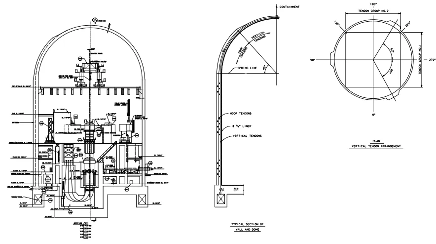
Fig. 1 Dimensions and Tendon Layout of Ulchin NPP Unit 6 PCCV
3. REQUIREMENTS FOR SIT
e requirements for SIT measurement in Korea are specified in the documents shown below. Table 1 sum arizes the requirements for SIT measurement.
NRC Regulatory Guide 1.685), Revision 2, August 1978, Initial Test Programs for Water-Cooled
Reactor Power Plants.
. U.S. NRC Regulatory Guide 1.1366), Revision 2, June 1981, Materials, Construction and Testing of
Concrete Containments.
E Code, Section III, Division 2, CC-60002), “Structural Integrity Test of Concrete Containments”
7)
, “Containment Structural Integrity Test (SIT)”, Document No. 9-445-Y450-008.
three-dimensional shell element, and the non-symmetric factors such as three buttresses and thickened wall near
main penetrations are modeled as shell elements proportional to thickness of the wall3,4).
According to the results of the comparison, the differences between the test and the analysis are in the displacement of the thickened wall near main penetrations. Some of the measured displacements exceed 30% of the expected analytical displacement. Residual displacements don’t meet the requirement of ASME CC-6000, which should be less than 10% of the maximum displacement. This study shows that the major reason for the problem is the shell modeling method with equivalent thickness. This study also shows that the strain in concrete at thickened portion of the wall doesn’t reach cracking strain as predicted by a local displacement control analysis.
2. DIMENSIONS OF PCCV
The PCCV of Ulchin NPP Unit 6 consists of 4 ft thick post-tensioned cylindrical concrete wall capped by 3 ft-6 in thick hemispherical dome and is supported by a circular nuclear island reinforced concrete basemat. The entire interior face of wall, dome and basemat is lined with 1/4 inch thick carbon steel plate to ensure leak-tightness. The dimensions are shown in Figure 1.
The cylindrical wall and hemispherical dome are post-tensioned with unbonded tendons in both the hoop and the meridional directions. Three buttresses are provided 120 degrees apart for anchoring the hoop tendon. The vertical inverted U tendons are anchored to the basemat below the cylindrical wall where tendon gallery exists to provide access to the tendon anchorage assembly shown in Figure 1.
Th m
a. U.S.
b
c. ASM d. KOPEC
Table 1
Summary of SIT Requirements (ASME)
Measurement Accuracy/Range Pressure Acceptance Criteria
Cracking
CC-6350 :
Cracks > 0.01"x6" at specified location
CC-6225 : Measuring device >0.005" at 0.003"
CC-6350 : Before test At Psit After test
CC-6420 : Review by designer
Strain CC-6370 (Concrete strain):
Prototype containment
CC-6224: Prototype containment
Displacement
at 60% of cylindrical wall height at 80% of cylindrical wall height at 100% of cylindrical wall height
2. During pressurization 20% Psit
Psit :
(1) Residual disp. < 20%
- Ra
at 20% of cylindrical wall height ll height
o o o o
ex and spring line or 0.01"
6361 :
dial disp.(AZ. 0o, 90 o, 180 o, 270 o)
CC-6223: ±5% of max. disp.
CC-6340: Data record 1. Pressurization Start
(b) No visible (c) Residual d
at 40% of cylindrical wa
at E/H (12 point) - Vertical displacement
60% Psit plus 0.01" plus measurem
at spring line & AZ. 0 , 90 , 180 , 270 at dome apex
at 2 points between ap
3. @Psit + 1hr
4. During depressurization
(2) Avg. radial disp. at ea < 20% of disp. at Psit pl
60% Psit - Measured displ. at Psit >
s measurement
Temperature correction
Range: Expected
CC-6380 :
Concrete at specified locations for strain
CC-6226 : ±2oF
40% Psit 20% Psit
displ. plu Psit : Res
Temperature
Pressure CC-6222 : ±
CC-6371 : Prototype containment
At Po (atmospheric pressure)
40% Psit
80% Psit
80% Psit
@Po
CC-6410 : (a) No rebar yielding
liner or concrete damage ispl.
- Measured displ. at Psit < 1.3 predicted displ. plus measurement tolerance at
of disp. at P sit
ent tolerance
ch elevation us 0.01" plus measurement tolerance
1.3 predicted tolerance at idual disp. < 10% of maximu
2% Psit
NALYS FOR PREDICTING DISPLA EMENT inite ement Model
A three-d ent model w e g ch
as equipment r c on
response. In ord tic beh ar these r esh w
interconnection e ba slab and shell e ll was in
simulate the sh el co ists of 3729 Fou ts, soil spring
el of global model se 1).
del
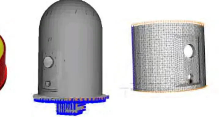
Fig. 2 Finite Element Model
imensional finite elem as used to analyz the PCCV includin large penetrations, su
hatch, personnel air-lock and th ee buttresses whi h will cause deviati from an axisymmetric
er to simulate a more realis avior ne egions, a refined m as developed. A rigid
between shell element in th se lement in the wa troduced to properly
ell/slab junction. The mod ns r-Node shell elemen nonlinear
ements and 3012 nodal points as shown in (Ca
m displacement at Psit
4. A IS C
4.1 F El
Figure 2. Figure 2(a) shows a part
Copyright © 2005 by SMiRT18
The concrete structure is modeled with composite shell elements consisting of a thin inner layer of steel representing the liner and a much thicker outer concrete layers. The bottom of the slab rests on a soil foundation, which is modeled by the nonlinear soil spring with tension cut-off. The component of the PCCV is modeled as linear elastic materials and the loading histories shown in Figure 6 are loaded as internal pressure.
The thickened section wall near the equipment hatch was modeled as follows;
a. The equivalent shell thickness of an element base was used to define variable thickness between thickened section wall of equipment hatch and normal section wall (Figure 2(a)).
b. The nodal thickness was used to define variable thickness between thickened section wall of equipment hatch and normal section wall (Figure 2(b)).
The local finite element model using solid elements was used to evaluate the concrete strain under displacements resulting from SIT test. The local model consists of a symmetric model of the cylindrical wall
between azimuth 60o~240o including the equipment hatch and height to spring line shown in Figure 2(c).
4.2 Analysis Results
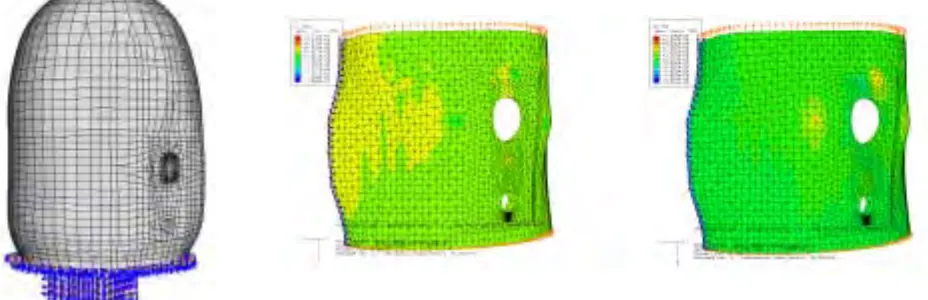
Figure 3 shows the deformation shape of PCCV. In global analysis the maximum displacement was 0.36in at the apex of the dome. The displacements at the thickened wall including the equipment hatch are very small. The maximum concrete strains are 0.000774 in/in for horizontal direction and 0.000606 in/in for vertical direction
w is less than the concrete cracking strain.
Fig. 3 Deformation Shape and Strain Contour
hich
(a) Deformation Shape (Magnitude=500) (b) Horizontal Strain Contour (c) Vertical Strain Contour
5. STRUCTURAL INTEGRITY TEST
5.1 Measuring System, Locations and Pressurization
The measurement locations for displacements were selected to meet the following specifications.
nts of the cylinder shall be measured at a minimum of five approximately equally ocated at 20%, 40%, 60%, 80% and 100% of the distance between the base and the
nts of t
ning
ent of the t
ent of t ally sp
disp a. Radial displaceme
spaced elevations l spring line. b. Radial displaceme
minimum of 12 poi diameter of the ope hatch.
c. Vertical displacem four approxima d. Vertical displacem
approximately equ azimuth.
Pressure, temperature and
he containment wall adjacent to the largest ope nts, four equally spaced on each of three conce
shall be measured in the horizontal and ve
op of cylinder relative to the base, shall tely equally spaced azimuths.
he dome of the containment at a point aced intermediate points between the apex an
lacement were measured and recorded to in
ning, shall be measured at a ntric circles. The increase in rtical directions of equipment
be measured at a minimum of
near the apex and two other d the spring line on at least one
spect the structural behavior under
IT pressure. Two pressure gauges were installed to measure the internal pressure and the outer atmosphere ressure of PCCV. The temperature sensors were also installed to measure the internal temperature and the
own in Figure 4. Displacements were measured at forty-five locations of the PCCV. Figure 5 shows the typical
measurement locations for r lacement at the equipment
hatch. A fiber optic sensor measurement system, Fiber Brag Grating (FBG), is used to measure the diameter S
p
atmosphere temperature. Extensometers were attached on the containment liner or internal concrete structure sh
adial displacement, vertical displacement and radial disp
displacement of equipment hatch sleeve.
Fig. 4 Measuring System
(b) Vertical displacement
Fig. 5 Measur
The maximum pressurization rate did not
compared with the predicted results. Pressurization at 10 was held at least for one hour and concrete surface crack
(a) Radial displacement
(c) Radial displacement at equipment hatch
ement Locations
Copyright © 2005 by SMiRT18
average temperature time histories measured during the test are shown in Figure 6.
Fig. 6 Pressure and Average Temperature Time Histories
5.2 Comparison T
Although various measuring systems includi
5: 30 8: 00 10 :30 13 :00 15 :30 18 :00 20 :30 23 :00 1: 30 4: 00 6: 30 9: 00 Date/Time 50 3/28
est Data with Pretest Analysis
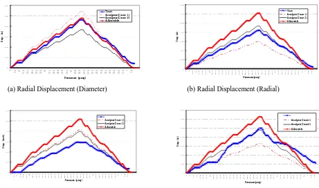
of test data with analysis result is shown in Figure 7. These figures sho tic response and the measured data are within allowable displacement. The m
which is a micro displacement, show that structural behavior during the de dual displacement rate (Figure 7(d)). A similar situation has been observe onstructed in Korea. Inspectors have judged that the situation is related . In Figure 7, the allowable maximum displacements are defined as 1.5 tim
0.2 0.25 0.3 0.35 Di sp . (i n) Test A nalysis(C ase 1) A nalysis(C ase 2) A llow able
The comparison w that the PCCV
exhi ts an elas easured data at the
equi ent hatch, pressurization has a
relatively large resi d in the SIT results
of ei ht PCCVs c to the accuracy of
measuring system es of analytical
predi tion of case 2.
n Resu
ng an optical sensor with an accuracy of 10-6 strain and an
Test A nalysis(C ase 1) A nalysis(C ase 2) A llow able 0 10 20 30 40 50 60 70 23 :30 2: 00 4: 30 7: 00 9: 30 12 :00 14 :30 17 :00 19 :30 22 :00 0: 30 3: 00 Pre s su re (psig) 60 70 mpe ure (F )
3/25 3/26 3/27
75 65 rat Te 55 bi pm g c 0.1 0.15 0
(a) Radial Displacement (Diameter) (b) Radial Displacement (Radial)
0 0 4 8. 6 10 11. 5 16. 5 21. 4 25 25. 2 29. 3 33. 2 34. 9 37. 1 41. 2 44. 9 44. 8 47. 8 51. 8 55. 7 56. 9 59. 8 63. 7 65. 9 60. 7 57. 5 53. 5 46. 7 43 37. 8 35. 3 33. 3 28. 6 25. 2 20. 4 14.
9 10 7
2. 5 0. 2 Pressure(psig) 10 11 .5 18 .1 24 .3 25 .2 30 .6 35 37 .1 42 .5 44 .8 47 .8 53 .1 57 59 .8 64 .9 63 .2 57 .5 51 .3 45 .3 37 .8 35 .1 30 .6 25 .2 18 .6 11 .3 7 1. 4
Pressure (psig)
0.5 0.6 Test 0.07 Test 0.1 0.2 0.3 0.4 0.5 0.6 0 5. 5 Di sp . (i n) 25. 2 29. 3 33. 2 34. 9 37. 1 41. 2 44. 9 44. 8 47. 8 51. 8 55. 7 56. 9 59. 8 63. 7 65. 9 60. 7 57. 5 53. 5 46. 7 43 37. 8 35. 3 33. 3 28. 6 25. 2 20. 4 14.
9 10 7
2.
5
0.
2
Pressure (psig)
Analysis(C ase 1) Analysis(C ase 2) Allow able
(c) Vertical Displacement at Dome Apex
Fig. 7 Compariso
(d) Radial Displacement at Equipment hatch
lts a
0 0.01 0.02 0.03 0.04 0 4 8. 6 10 11 .5 16 .5 21 .4 25 25 .2 29 .3 33 .2 34 .9 37 .1 41 .2 44 .9 44 .8 47 .8 51 .8 55 .7 56 .9 59 .8 63 .7 65 .9 60 .7 57 .5 53 .5 46 .7 43 37 .8 35 .3 33 .3 28 .6 25 .2 20 .4 14.9 10 7 2.
5 0. 2 Pressure(psig) Di s p .(i n) Allow able
t Typical Location
ere used for the Ulchin NPP Unit 6 SIT, the results were the same. This study performs the evaluation of the elastic behavior using response strain due to displacements from the SIT. The ev uation result shows that the maximum strains are less than concrete cracking strain.
As shown in Figure 7, the predicted results using model case 1 were different from the results of model case 2. Case 2 analysis results are reasonably in agreement with test results. The result from Case 1 analysis at the equipment hatch shows an apparent difference with test data. According to ASME Section III, Division 2, CC-6000, the allowable value is calculated as 1.3 times the pretest analysis results. If the test data at maximum pressure exceed the allowable value, the residual displacement of the PCCV should be less than 10 percents of
the m um displacement of the structure. The displacements at the equipment hatch are very small values less
than 0.1 in and the violation of ASME CC-6410 criteria sometimes represents in SIT results.
If the test data at SIT pressure are less than the allowable displacement, the requirement of ASME CC-6410 can always be satisfied because the criteria for displacement is relatively much larger than the above case. The al
th
finite element model, case 2 m
6. CONCLUSIONS
REF
Division 2, CC-6000, “Structural Integrity Test of Concrete of a 1:4-Scale Prestressed
S. NRC Regulatory Guide 1.68, Revision 2, (August 1978), Initial Test Programs for
extensometer with accuracy 10-3 w
al
axim
lowable displacement is calculated based on the results of the pretest analysis. Therefore accurate prediction of e behavior of the PCCV is very important for evaluation of an elastic behavior of the structure and the revised
odel, proposed in this study addresses the problem.
Based on a review of the analysis, we can draw the following conclusions:
By changing from an equivalent shell thickness model to a variable shell thickness model based on a nodal thickness, the prediction accuracy due to pretest analysis can be improved and thus the results are in good agreement with structural integrity test data.
The displacements at the equipment hatch are very small and the code violation, which isn’t returned after unloading to the initial position more than 90%, sometimes represents in Korea.
Although the residual displacement at the equipment hatch sometimes exceeds the allowable requirement specified in ASME Code, CC-6410 (c), the concrete maximum strain due to detail analysis is always being less than concrete cracking strain. Visual inspection result around the equipment hatch also verifies the concrete integrity.
Recommendations of this study are as followings:
That case needs to estimate the concrete strain by a local finite element analysis under the test displacement loading and then the assessment of structural elastic response should be performed based on the concrete strain.
The AMSE Code CC-6410 (c) and (d) should be applied only to the maximum radial and vertical displacements and isn’t in appropriate to apply the area with small displacement/strain such as around the equipment hatch.
ERENCES
1. Korea Hydraulic and Nuclear Power Co., Ltd, (2004), “Report for Structural Integrity Test, Ulchin Unit 6.”
2. ASME Code, (2002), Section III, Containments.”
3. Sandia National Laboratories, (2003), “Overpressurization Test Concrete Containment Vessel Model.”
4. Luk, V.K., (2001), “Pretest Round Robin Analysis of A Prestressed Concrete Containment Vessel Model,” NUREG/CR-6678.
5. U.
Water-Cooled Reactor Power Plants.
6. U.S. NRC Regulatory Guide 1.136, Revision 2, (June 1981), Material, Construction and Testing of Concrete Containments.