Random Vibration of the Simplified Cracked Liners
Yung-Tze Chen, Ph.D., P.E.
Civil & Hydraulic Engineering Research Center, Sinotech Engineering Consultants, Inc.,Taipei, Taiwan ABSTRACT
This is a study of random vibration of the simplified linear elastic cracked liners. An analytical method for random vibration of the simplified cracked liners subjected to a stationary ergodic white-noise pressure loading with simply supported boundary conditions is developed by means of the Galerkin method coupled with integral transform method. Through 3-D plot, rms deflection ratios (crack/without crack) for a typical cracked liner plate will be exclusively presented. Results for this analysis are used to draw conclusion regarding the ability of relating rms deflection ratios to aspect-ratios, to crack-width ratios, to crack-depth ratios.
INTRODUCTION
The vibration of rectangular plates with internal crack has been treated extensively in [3,5,8,9]. Up-to-date there is little study on the random vibration of simply supported liner plate with internal partial-in-depth crack.
In this paper, the Galerkin method coupled with integral transform method [1,2,4] are applied for determining the random vibration of partial-in-depth cracked rectangular liner plates simply supported on four edges. Selected typical 3-D plots tied to the above methods are exclusively expressed as well.
Special approach by using extended Heaviside functions is employed to treat the discontinuous variation of the subject of bending stiffness.
Through the proposed methodology, it makes the related physical phenomena of partial-in-depth cracked liner plate random vibration more clearly understandable than ever.
ANALYSIS AND F O R M U L A T I O N
A thin, elastic, isotropic, homogeneous simply supported rectangular liner plate of uniform thickness h with sides a and b containing an internal partial-in-depth crack hxi x bxi x Ay (crack depth x crack length x crack width) located at (xi, yj) is shown in Figure 1; Ay is an infinitesimal crack width.
Based on the Kirchhoff-Love hypothesis, the governing equation of the subject liner plate is derived by utilizing the following Hamilton's principle:
61 = 6 ~1 ~ ( T - U - V)dt = 0 (1)
where T = the kinetic energy; U = the strain energy; V = the potential energy produced by external loads; and 6 = the first variational operator.
The location of the subject liner plate middle surface varies due to the variation of crack depth. For the simplified assumption purpose, the middle surface is assumed to locate on a surface that bisects the thickness at each point and to vary discontinuously at the boundary line between crack depth and left-over-thickness.
The strain energy U is given by
U= -~ I ~' I ~ ( M x K ~ + M , K y + 2M~yK~y)dxdy 1 (2)
where Kx, Ky and Kxy = the curvatures and twist of the middle surface, respectively, as defined by
Kx = - w .... (3)
Ky = - W.yy (4)
Kxy = - w xy (5)
= ) . ,
SMiRT 16, Washington DC, August 2001 Paper # 1515
where w = the deflection.
similarly, Mx, My and Mxy = the bending and twisting moments per unit width, respectively; they are written as Mx = -Dod(x,y)(
W, xx + uW, yy )
M = -Dod(x,y)
(W, yy + UW, xx)
Mxy = -(1-O )Dod(x,y).W, xy
(6) (7)
(8)
in which Do = the flexural rigidity of a reference liner plate neglecting partial-in-depth cracks, as given by Do = Eho3/[ 12(1- u 2)] (in which ho = reference liner plate thickness; E=Young's modulus; and u = Poisson's ratio); and d(x,y) is defined as
d(x, y)= 1+ g~x, H(x-xI)+ ~'yy H(y-yj)+ ~y,,j H(x-xi).H(y-yj) (9)
where constants ( , , , (yj and
(xy,.j
are given by/ 3
( x - - ,ho +1 - 1 (10)
13
fly j= ( h°
+1 - 1 (11)/ 13
(xyo.= hxy'J +1 - 1 . ( , , . ( y j
ho
(12)and H(x-xI), H(y-yj ) =the extended Heaviside functions. Hence, the strain energy U becomes
1 ~od(X,
[(kx )2 (ky)2
.
)2
U = -~ f
Y)"
+
+ 2vk, Kv +
2(1-vXk,y}txdy
(13)The first variation of the potential energy 6V produced by external lateral loads p can be expressed as [6]
av:-f ~(p-cw)~dxdy+ ~(mr~,,-m,,~w,,+q,~)dy[o
+ f(my6Wy - my6W
+qy6w)dx[: (14)in which c = damping coefficient; and qx, qy, mx, my, mxy, and myx = external transverse forces and external moments prescribed on boundary edges, respectively.
The kinetic energy T can be written as
T = 1
-~ ~ (~(w)~
~m °
dy
(15)in which the dot indicates differentiation with respect to time; and the notations (h and mo are defined as
~
(h~,')
lh,~,..,-hx,-hY,)h,,
(h(X,y)=l+ (
)H(x-x,)+~-~o ]H(y-Y/)+
•
mo = ,oh o (17)
in which hxi, hyj = i and j th cracked heights, respectively; 9 = the mass density of the liner plate. 15. into Eq. 1., the differential equation of motion can be obtained as
Substituting Eq. 13. ~ Eq.
m0(h fb eft; p
+ - - - - + (dw .... ) .... + (dw, yy ),yy + v(dw, x x),yy + v(dwyy ),~x + 2(1 - v)(dwxy ),xy = 0 (18)
Do Do Do
associated with the following boundary conditions
either w = 0 or (Dodw,xx),x + V(DodW, yy),x + 2(1 - v)(DodW,xy),y - V = 0
along the edges x = 0 and x = a (19)
either W.x = 0 or Dod(wxx .at- V W,yy) - mx = 0 along the edges x=0 and x=a
(20)
either w = 0 or 2(1- v )Dodw,xy = mx at each comer (21)
in which Vx = the Kirchhoff's supplementary force. The similar boundary conditions can be written along the edges y = 0 and y = b.
If the coefficients £'/, and d go to 1, then the governing equation derived will be reduced to the general equation for a uniform liner plate without crack.
F R E E T R A N S V E R S E V I B R A T I O N S O F L I N E R P L A T E W I T H P A R T I A L - I N - D E P T H C R A C K
Let w(x,y,t) = N (x,y)sin(C0mnt + 0o) (22)
where N (x,y) = a function of x and y; co ... = natural frequency; and 00 = the initial phase.
for free transverse vibrations (i.e., p=0 and c=0), the following equation for N (x,y) is obtained.
Applying Eq. 22. to Eq. 18
2 m°fh N = 0
(cl-~ .... ),~ + (d-~,y, ) yy + V(d-~ ),,y + V(d-~ y ) xx + 20 - v~dwxy ) ~y - co .... "D----o- (23)
The natural frequencies of a rectangular liner plate with partial-in-depth crack are presented by means of the Galerkin method. N o w N (x,y) is expressed as
N(x, y) = Zw--, sin .... .sin
m=l it=l
(24)
where N = t h e unknown coefficient; and s i n t ~ J and s i n [ 2 ~ J =functions satisfying the simply supported boundary
\ j \ j
conditions for the subject liner plate. After lengthy calculation, the Galerkin equation of Eq. 23. can be simplified as
co ... = f~ + + 2 ( 1 - v ) • f ' • D° 1/2 (25)
mo(,,ab
where fo = c°s(2mxirc) sin(mbxirC)" 2 (
a a mTc
• sin(nbyj zc 2b
b )"
(bfyj + bxifxye,j)
n ~ (26)
2mxirc ) b cos(2nbJrC
;and fl = ab + (xib[bxi a cos( • sin(mbxizc) + ( y j a[byj n~r J
m ~ a a
. sin( nb yj rc b 2rty j ~
b ) ] + ( x y i ' j [ b x i - a c ° s ( ? m x i T C ) ' s i n ( m b x i ~ ) ] ' [ b y j - ~ c ° s ( )
mzc a a n~ b
. sin( nbyj rc
b )] (27)
where bxi, byj = i and j the cracked widths, respectively.
If the cracked width byj is approaching zero, then partial-in-depth crack in x-direction will be simulated. Furthermore, if the cracked width bxi and by i a r e set to zero, then fo=0 and f~=ab accordingly, in turn the subject frequency Eq. 25. will be reduced to uncracked frequency equation as[5]
... = [(mzc)2 + (~-)2 ]" I D ° a m o
(28)
Eqn. 25. can be rewritten as
~mn I D ° Lmn21D~o . . . "- (29)
( O m n : a ~ m T : b---T-
: fl 2 a 2 .(n~a)2 . f o } (30)
in which Lmn (h ab {[(mzc) +(n~:-~) ]+ 2(1-v)(mzr) 2 .--if-- fl
b 2
; a n d Lmn2 = 2 2mn (31)
a
Finally, the mean square value of deflection response ( for 1 st natural frequency only ) due to the white-noise pressure excitation So can be expressed as
2 SOW,, (32)
W " - ' ~
8 ( k ~
were w,, = 1st liner plate natural frequency; k = the spring constant of liner plate.
Providing that
1. So ( w,, ) is relatively smooth in the neighborhood of w,,. 2. ( is small ( ( < 0.20 ).
NUMERICAL RESULTS
The random vibration for a liner plate subjected to stationary ergodic white-noise pressure loading with partial-in-depth crack has been presented by means of the Galerkin method.
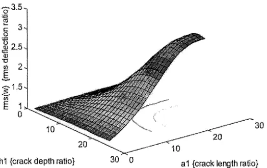
as shown in figures 2,3 & 4. Finally, at critical crack case with a~=0.96 & hl=l.0, there exhibits maximum rms deflection ratio for a/b=2/3, then for a/b=l and last with a/b=2/5.
CONCLUSION
The rational approach for random vibration of an elastic, isotiopic, homogeneous rectangular liner plate with partial-in- depth crack has been proposed with success by means of the Galerkin method.
Conclusion can be drawn in regards to that the rms deflection ratios are always greater than the uncracked ones in essence, plus the former can also be related to the aspect-ratios, crack-width ratios, and crack-depth ratios. In terms of critical crack case, maximum rms goes to a/b=2/5, then for a/b=1 and last for a/b=2/3.
R E F E R E N C E S
1. Chen, Y. T., 1997, "On the Vibration Problem of Power Plant Floors", SEC/R-ST-97-02, Sinotech Eng. Consultants, Inc. Taiwan.
2. Chen, Y. T., 1999, "On the Application of Fracture Mechanics to the Cracks and Strengthening of Reinforced Concrete Slab", SEC/R-ST-99-081 Sinotech Eng. Consultants, Inc. Taiwan.
3. Chen, Y.T., 2000, "Free Vibration of Cracked Plates", Proc. Int. Conf. on Advances in Structural Dynamics, pp.627-634. 4. Hirano, Y. and Okazaki, K., 1980, "Vibration of Cracked Rectangular Plates", Bull. JSME 23, pp. 732-740.
5. Leissa, A. W., 1969, "Vibration of Plates", NASA. SP- 160.
6. Lynn, P.P. and Kumbasar, N., 1967, "Vibration of Thin Rectangular Plates having Narrow Cracks with Simply Supported Edges", Developments in Mechanics, Proc. of the 10 th Midwestem Mechanics Conf. Colorado State Universety, Fort Collins,Co. pp. 911-928.
7. McFarland, D. E., Smith, B. L., and Bemhart, W. D., 1972, "Analysis of Plates", Spartan Books.
8. Stahl, B. and Keer, L. M., 1972, "Vibration and Stability of Cracked Rectangular Plates", Int. J. Solids Structures 8, 69-91. 9. Crandall, Stephen H., "Random Vibration", Technology Press John Wiley&Sons, 1958.
Ay Gy
MIOOLE PLANE
(a)
Qx - Z
Qy
FCx,y,t) ~ . _
... I1_1 .. . [ / ' ~ M y x - x
, ~ M y x _
" % M
. . . Y l __
...
: ~ J
O x + ~x
d x-
Oy + aQ---LY dy ~Y
(b)
Figure 1 (a)Positive State of Stresses for Cracked Plate (b)Differential Cracked Plate Element(Middle Surface)
with Stress Resultants.
rms defecti!on=mtio @ [al~=t;(m,:n)=(t, I ! ~);:a :t ={" 0 ~" ,96};ht={.0417,1,0}]
~i4J
. .: • .
30
ht {crack depth ratio} 30 0 al {crock ~:leNth ratio}
rms: deflection ratio @ [alb=213;(m,n)=(t, t );a I ={.04-,96};h1={,04 !7-1. O}
~ 2 . 5 -
~5 C
o
:%
¢,0
hi {orack depth ra~io}
10 ... :: .,,,,,,,.:.: ,,. . . 30
10
30 0 al: {crack length ratio}
Figure 3 Rms Deflection Ratios due to White-Noise Pressure Loading for a/b=2/3
rms deflection ratio @ [a~=215;(m,n)=(t,1):;at={,O4~,96};hi={,041:7-1.0}
: ,3.51
0
2.5,
0
t 0 30
~ 1 0
ht {crack :depth ratio} 30 0 al {crack: length ratio}