Maintenance Manual
®
functions, or features, at any time, without notice.
NEC America, Inc. has prepared this document for use by its employees and customers. The information contained herein is the property of NEC America, Inc. and shall not be reproduced without prior written approval from NEC America, Inc.
NEAX and Dterm are registered trademarks of NEC Corporation. MATWorX is a trademark of NEC Corporation.
Copyright 2000
NEC America, Inc.
ISSUE 1 ISSUE 2 ISSUE 3 ISSUE 4
DATE JANUARY, 2000 DATE DATE DATE
ISSUE 5 ISSUE 6 ISSUE 7 ISSUE 8
DATE DATE DATE DATE
NEAX2000 IVS2
Maintenance Manual Revision Sheet 1/2
ISSUE 1 ISSUE 2 ISSUE 3 ISSUE 4
DATE JANUARY, 2000 DATE DATE DATE
ISSUE 5 ISSUE 6 ISSUE 7 ISSUE 8
DATE DATE DATE DATE
NEAX2000 IVS2
Maintenance Manual Revision Sheet 2/2
TABLE OF CONTENTS
Page
LIST OF FIGURES . . . iii
LIST OF TABLES . . . iv
INTRODUCTION . . . 1
PURPOSE . . . 1
USING THIS MANUAL . . . 1
REFERENCE MANUALS . . . 2
CHAPTER 1 MAINTENANCE SERVICE FEATURES . . . 3
HOW TO READ THIS CHAPTER. . . 4
FAULT MESSAGES . . . 5
General Description . . . 5
Service Conditions . . . 6
Programming Procedure . . . 7
Operating Procedure . . . . 11
STATION LINE STATUS DISPLAY . . . 32
General Description . . . 32
Service Conditions . . . 32
Programming Procedure . . . 32
Operating Procedure . . . . 32
BATTERY RELEASE CONTROL . . . 34
General Description . . . 34
Service Conditions . . . 34
Programming Procedure . . . 34
Operating Procedure . . . . 35
STATION/TRUNK STATUS DISPLAY . . . 36
General Description . . . 36
Service Conditions . . . 36
Programming Procedure . . . 37
Operating Procedure . . . . 37
DIAGNOSTICS . . . 38
General Description . . . 38
Service Conditions . . . 38
Programming Procedure . . . 39
Operating Procedure . . . . 39
BATTERY REPLACEMENT . . . 46
PERIODIC ALARM . . . 47
General Description . . . 47
Service Conditions . . . 47
CHAPTER 2 TROUBLESHOOTING . . . 51
PRECAUTIONS . . . 52
Procedure for Unplugging/Plugging Circuit Cards . . . 52
Static Electricity Guard . . . 53
Turning Power ON . . . 56
Turning Power OFF . . . . 57
OUTLINE OF TROUBLESHOOTING . . . 58
FAULT DETECTION. . . 59
FAULT DIAGNOSIS AND TROUBLESHOOTING . . . 65
Display on MAT/CAT . . . 65
Fault Message . . . . 65
Station Line Status Display . . . 80
Lamp Indication on Cards . . . 83
Troubleshooting by Contents of Complaint . . . 95
Explanation of Symbols in Troubleshooting Procedure . . . 96
How to Follow the “Tree” . . . 96
Station Line Fault . . . . 98
C.O. Line/Tie Line Fault . . . 101
Power Failure Transfer (PFT) Fault . . . 111
Dterm Fault . . . 112
ATTCON Fault . . . 114
DSS Console Fault . . . 116
ATTCON Self-Test Procedure . . . 117
CHAPTER 3 MAINTENANCE OPERATION . . . 121
DATA SAVING . . . 122
DATA LOADING . . . 123
Figure 1-1 System Diagram of Battery Release Control . . . 34
Figure 1-2 Periodic Alarm Indications . . . 47
Figure 2-1 Static Electricity Guard (1 of 2) . . . 53
Figure 2-1 Static Electricity Guard (2 of 2) . . . . 54
Figure 2-2 Troubleshooting Outline . . . . 58
Figure 2-3 Alarm Indication Routes . . . . 59
Figure 2-4 Sections for Troubleshooting Procedure . . . 95
Figure 2-5 How to Follow the “Tree” . . . 97
Table 1-1 Fault Occurrence Kind Number . . . 12
Table 1-2 Fault Restoration Kind Number . . . 13
Table 1-3 Standard Data Set of External Alarm Kind . . . 14
Table 1-4 Alarm Kind and Alarm Lamps . . . 15
Table 1-5 Fault Information . . . 16
Table 1-6 Fault Restoration Information . . . 17
Table 1-7 Examples of Fault Occurrence Display Using MATWorX . . . 25
Table 1-8 Example of Fault Restoration Display Using MATWorX . . . 30
Table 1-9 Status of Single Line Telephone and Dterm . . . 33
Table 1-10 Station Status Information . . . 40
Table 1-11 Trunk Status Information . . . 43
Table 1-12 Alarm Information . . . 45
Table 2-1 Procedure for Unplugging/Plugging Circuit Cards . . . 52
Table 2-2 Lamp Indications on Circuit Cards . . . 61
Table 2-3 Remedial Action on Each Fault Kind . . . 67
Table 2-4 Fault Restoration Information . . . 78
Table 2-5 Line Status and Remedial Action . . . 81
INTRODUCTION
PURPOSE
This manual explains the maintenance service features provided with the NEAX2000 IVS2, and the recommended troubleshooting procedure when a fault has occurred, for maintenance per-sonnel of this system.
USING THIS MANUAL
This manual contains the following chapters:
CHAPTER 1 MAINTENANCE SERVICE FEATURES
This chapter describes the general description, service conditions, programming, and operating procedures of the maintenance service features.
CHAPTER 2 TROUBLESHOOTING
This chapter describes the precautions before troubleshooting and the troubleshooting proce-dure flowchart.
CHAPTER 3 MAINTENANCE OPERATION
REFERENCE MANUALS
Refer to the following manuals during maintenance and troubleshooting:
Command Manual Describes the Customer Administration Terminal (CAT) op-eration, command function, and setting data required for programming the PBX system.
MATWorX Studio User’s Guide Provides information to install and use the MATWorX Studio program. Includes highlight about features of the program. This guide is a supplement to the MATWorX Studio online Help system, which provides context-sensitive information and procedures to perform tasks using the MATWorX Studio.
MAINTENANCE SERVICE
FEATURES
HOW TO READ THIS CHAPTER
In the programming procedure, the meaning of (1), (2), and marking are as follows:
(1): 1st Data
(2): 2nd Data
: Initial Data
FAULT MESSAGES
General Description
This feature stores fault information into the Fault Store Memory and displays the fault informa-tion on the Maintenance Administrainforma-tion Terminal (MAT) or the Customer Administrainforma-tion Terminal (CAT). The display format is shown below:
(1) Display Format on CAT/MAT by Command Operation
The fault information is separated into four parts and displayed on four screens.
1ST SCREEN
1: 01 MN MP 00
2: 99/10/24 20:31 2ND SCREEN
4TH SCREEN
3: X X X X X X X X
4: X X X X X X X X
DATE AND TIME OF FAULT OCCURRENCE AND RESTORATION
3RD SCREEN
FAULT INFORMATION/
FAULT INFORMATION/
TO 1ST SCREEN OF NEXT INFORMATION
FAULT RESTORATION INFORMATION
FAULT RESTORATION INFORMATION
CPU KIND AND NO. THAT DETECTED THE FAULT MP 00 : MP
FP 00-03 : FP NO. 0-3 AP 04-15, 20-31 : AP NO. 4-15, 20-31
ALARM KIND (MJ/MN/–)
(2) Display Format using MATWorX Studio
The fault information displays in the order that faults occur.
Service Conditions
(1) Printout of fault information is possible through the printer connected to the MAT.
(2) The maximum number of fault information that can be stored is 64. If the stored information exceeds 64, the storing method (either overwriting new data or not storing new data) can be selected by CM08>451.
(3) To provide external alarm indication, equipment such as an Alarm Display Panel must be installed. External alarm indication is provided using a contact to ground at the main distribution frame. One contact is needed for minor alarms, and one contact is needed for major alarms.
(4) The alarm kind (Major Alarm, Minor Alarm, or No Alarm Indication) can be programmed by CMEA Y=2 for each fault kind.
Date and Time of Fault Occurrence and Restoration: Year, Month, Date, Time
CPU Kind and Number : CPU No. Detecting Fault Occurrence/ Fault Restoration
MP, APxx Fault Occurrence Kind No./Fault Restoration Kind No.
Renewal Date of Fault Content
Fault Information/
Programming Procedure
DESCRIPTION DATA
Enable the fault information storage feature.
(1) (2)
450
1 : To be provided
Specify the processing at the time of fault storage memory overflow.
(1) (2)
451
0 : No fault information is registered in case of fault memory overflow 1 : Fault information is overwritten in
case of fault memory overflow
Assign which kind of fault information is stored into the fault information memory, and which kind of fault indi-cates an alarm.
NOTE 1: Even if the external alarm
may be set as MN or MJ alarm for system initialized (1st data=01), no alarm is output in the case of Power On, Reset key operated, ini-tialization from the MAT/ CAT, and initialization by MP SW3 switch selection.
NOTE 2: The External Alarm Kind for
“Number of faulty trunks was more than predeter-mined number” is assigned by CM42>06, 07. When CM42>06, 07 is assigned, the 2nd data of CMEA Y=2 simply means the fault infor-mation is to be registered into Fault Memory. In this case, Alarm Kind cannot be changed.
•
(1) Y=2
01 : System initialization NOTE 1 04 : MP-FP/AP communication failure 08 : FP/AP card down
09 : Power failure
12 : CS/ZT fault occurred 16 : Periodic alarm
18 : FP/AP card returned to normal condition
19 : Power failure returned to normal condition
20 : DTI line failure
21 : DCH/BRT/PRT D-channel link connection failure
22 : CCH link connection failure
24 : Number of faulty trunks was more than predetermined number
DESCRIPTION DATA
NOTE 3: The External Alarm Kind for
“Number of lockout stations was more than predeter-mined number” is fixed as MN. The 2nd data of CMEA Y=2 simply means the fault information is to be regis-tered into Fault Memory. In this case, Alarm Kind cannot be changed.
NOTE 4: The External Alarm Kind for
“Number of faulty trunks was less than predeter-mined number” is fixed to No Alarm. The 2nd data of CMEA Y=2 simply means that the fault information is to be registered into Fault Memory. In this case, Alarm kind cannot be changed.
(1) 25 : Number of lockout stations was more than predetermined number
NOTE 3
26 : DLC card down
27 : Synchronism of DPC missed 28 : SMDR output buffer memory
overflow
2B : CS/ZT fault occurred
30 : DTI line returned to normal condition
31 : DCH/BRT/PRT D-channel link connection returned to normal condition
32 : CCH link connection returned to normal condition
34 : Number of faulty trunks was less than predetermined number
NOTE 4
[Australia Only]
CMEA A
DESCRIPTION DATA
NOTE 5: The External Alarm Kind for
“Number of lockout stations was less than predeter-mined number” is fixed to No Alarm. The 2nd data of CMEA Y=2 simply means that the fault information is to be registered into Fault Memory. In this case, Alarm Kind cannot be changed.
NOTE 6: CMEA programming can be
set using the Fault Storage add-in of MATWorX.
(1)
(2)
35 : Number of lockout stations restored to less than pre-determined number NOTE 5 36 : DLC card returned to normal
condition
37 : Synchronism of DPC returned to normal condition
38: : SMDR output buffer memory returned to normal condition 3B : CS/ZT returned to normal
condition
0 : Fault memory store/No External Alarm output
1 : Fault memory store/External Alarm is MN alarm
2 : Fault memory store/ External Alarm is MJ alarm
3 : Fault memory store/External Alarm Kind is determined by standard data
NONE : No fault memory store/No External Alarm output
Assign the number of stations in line lockout to give MN (minor) alarm.
(1) (2)
01
01-99 : Number of lockout stations CM42
CMEA
To clear the MJ/MN alarm by external key, perform the following programming.
DESCRIPTION DATA
Assign the card number for external key interface (PN-DK00) to the desired LEN.
NOTE 1: The card number of the
ex-ternal key interface (PN-DK00) must be assigned to the first LEN (LEVEL 0) and third LEN (LEVEL 2) of each card slot.
NOTE 2: Circuit No. 3 of E963 is used
for built-in External Key In-terface of MP card by set-ting CM61.
(1)
(2)
000-763: LEN
E900-E963:
Card No. of external key interface (PN-DK00)
For PIM0/1: E900-E915 For PIM2/3: E916-E931 For PIM4/5: E932-E947 For PIM6/7: E948-E963
Assign the function of MJ/MN alarm clear key to the external key.
•
(1)
(2)
YY=30
XX Z
XX : Card No. of PN-DK00 (00-63) Z : Circuit No. (0-3)
633 : MP built-in External Key Interface
00: MJ/MN alarm clear key CM61
CM10 START
Operating Procedure
(1) To Display Fault Message by CAT
The following flowchart shows the operation procedure for displaying fault messages by entering a command code (CMEA Y=0) from the CAT or by using the MOC Terminal feature or the MAT function in the MATWorX Studio.
Operation:
: Fault Kind Number (See Table 1-1.)
: External Alarm Kind (MJ/MN) (See Table 1-3.) CPU Kind and Number that detected the fault
MP00 : MP
FP00-03 : FP Number 0-3
AP04-15, 20-31 : AP Number 4-15, 20-31
: Date and Time of Fault Occurrence and Restoration
- : Fault Information/Fault Restoration Information (See Table 1-5.) DE DE + EA0 DE DE DE DE DE DE ST DE + 00
DE DATA NOT FOUND
2: 99/10/25/13:30
4: F0 FF FF FF 3: F0 FF FF FF 1: 01 – – MP00
11 12
For explanation of data
through , refer to the following list. 1 12 INFORMATION 1 INFORMATION 2 INFORMATION 64 10 9 7 8 6 5 3 4 2 1 COMMAND= EA0>
1: 01 – – MP00
2: 99/10/25 13:30
3: F0 FF FF FF
4: FF FF FF FF
1: 20 – – AP 06
2: 99/10/25 16:00
3: F0 FF FF FF
4: FF FF FF FF
1 2 3
: Fault Kind Number
Table 1-1 Fault Occurrence Kind Number
FAULT KIND NUMBER FAULT CONTENT
01 System initialization
04 MP-FP/AP communication failure
08 FP/AP card down
09 Power failure
12 CS/ZT fault occurred
16 It is a day for periodic maintenance
20 DTI line failure
21 DCH/BRT/PRT D-channel link connection failure
22 CCH link connection failure
24
[Australia Only]
Number of faulty trunks was more than predetermined number
25 Number of lockout stations was more than predetermined number
26 DLC card down
27 Synchronism of DPC missed
28 SMDR output buffer memory overflow
2B CS/ZT fault occurred
Table 1-2 Fault Restoration Kind Number
FAULT KIND NUMBER FAULT RESTORATION CONTENT
18 FP/AP card returned to normal condition 19 Power failure returned to normal condition 30 DTI line returned to normal condition
31 DCH/BRT/PRT D-channel link connection returned to normal condition
32 CCH link connection returned to normal condition 34
[Australia Only]
Number of faulty trunks was less than predetermined number
35 Number of lockout stations was less than predetermined number 36 DLC card returned to normal condition
37 Synchronism of DPC returned to normal condition
38 SMDR output buffer memory returned to normal condition
: External Alarm Kind (MJ/MN/–)
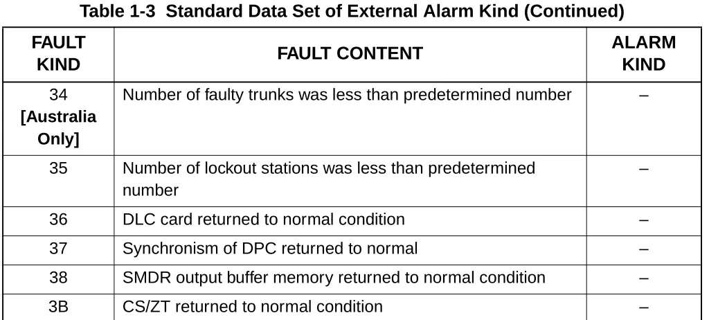
External Alarm Kind—Minor (MN), Major (MJ), or no alarm (external alarm not provided) is programmed by CMEA Y=2. Table 1-3 shows the standard data set by the 2nd data=3 of CMEA Y=2.
Table 1-3 Standard Data Set of External Alarm Kind
FAULT
KIND FAULT CONTENT
ALARM KIND
01 System Initialization MN ALARM
04 MP-FP/AP communication failure MN ALARM
08 FP/AP card down MN ALARM
09 Power failure MJ ALARM
12 CS/ZT fault occurred –
16 It is a day for periodic maintenance –
18 FP/AP card returned to normal condition –
19 Power failure returned to normal condition –
20 DTI line failure MN ALARM
21 DCH/BRT/PRT D-channel link connection failure MN ALARM
22 CCH link connection failure MN ALARM
24
[Australia Only]
Number of faulty trunks was more than predetermined number MJ/MN ALARM
25 Number of lockout stations was more than predetermined number (Refer to CM42>01 in Command Manual.)
MN ALARM (Fixed)
26 DLC card down –
27 Synchronism of DPC missed MN ALARM
28 SMDR output buffer memory overflow MN ALARM
2B CS/ZT fault occurred –
30 DTI line returned to normal condition –
31 DCH/BRT/PRT D-channel link connection returned to normal condition
–
32 CCH link connection returned to normal condition –
The alarm lamps in Table 1-4 are indicated according to the alarm kind. 34
[Australia Only]
Number of faulty trunks was less than predetermined number –
35 Number of lockout stations was less than predetermined number
–
36 DLC card returned to normal condition –
37 Synchronism of DPC returned to normal –
38 SMDR output buffer memory returned to normal condition –
3B CS/ZT returned to normal condition –
Table 1-4 Alarm Kind and Alarm Lamps
Alarm Lamp
Alarm Kind
External Alarm Indication
MJ
External Alarm Indication
MN
PZ-PW121 MJ
PZ-PW121 MN
MJ Steady light – Steady light –
MN – Steady light – Steady light
Table 1-3 Standard Data Set of External Alarm Kind (Continued)
FAULT
KIND FAULT CONTENT
- : Fault Information/Fault Restoration Information
Table 1-5 Fault Information
FAULT KIND NUMBER
01 Initial Kind,
,
System Initialization Information
04 Communication Failure Kind Number of Communication Failures FP/AP No.
08 FP/AP No.
09 Power Failure
Kind 1
Power Failure Kind 2
Power Failure Kind 3
12 Fault Kind AP No. CS/ZT Interface No.
16 Inspection Kind
20 Fault Detail Kind
21 D-ch No.
22 CCH No.
24
25
26 DLC Failure
Kind
LEN Station No.
27 DPC Failure
Kind
DPC No.
28 Memory Kind Overflow Kind
2B Fault Kind AP No. CS/ZT Interface No.
5 12
5 6 7 8 9 10 11 12
a b c
d
e
e
f f f
Table 1-6 Fault Restoration Information
FAULT KIND NUMBER
18 FP/AP
No.
19 Power Failure
Kind 1
Power Failure Kind 2
Power Failure Kind 3
30 Fault Detail
Kind
31 D-ch No.
32 CCH No.
34
35
36 DLC Failure
Kind
LEN Station No.
37 DPC Failure
Kind
DPC No.
38 Memory
Kind
3B Fault Kind AP No. CS/ZT Interface No.
5 6 7 8 9 10 11 12
e
k k k
l
m
n
o
p q
r
s
t
: Kind of System Initialization information (Upper digit)
1: Program address information 2: Receive command information F: No system initialization information
: Initial Kind (Lower digit)
0: Power On Initialize
1: Initialize by Reset Button (SW1) 2: Serious failure 1
3: Serious failure 2 4: Not used
5: Serious failure 3 6: Serious failure 4 7: Serious failure 5 8: Serious failure 6
9: SW3 was changed to 0 A: Serious failure 7
B: Initialize by CAT/MAT C: Not used
D: Not used E: Not used F: Not used
: System Initialization Information
The address of the program which caused system initialization
: Communication Failure Kind
00: Overflow of data sending buffer to the FP/AP 01: Invalid data received from FP/AP
: FP/AP Number
00-03 : FP No. 0-3
04-15, 20-31 : AP No. 4-15, 20-31 a
b
c
d
: Power Failure Kind
00: AC input failure 01: Fuse break 02: PWR alarm
: Fault Kind
00: Fault notice from CS/ZT 01: CS/ZT initial failure
02: CS/ZT condition read failure 03: CS/ZT condition unmatch 04: B channel condition unmatch 05: SYS-ID upload failure
06: SYS-ID download failure 07: CS/ZT make busy failure 08: CS/ZT data load failure 09: B channel make busy failure
0A: CS/ZT operation parameter change failure 0B: LCCH sending position failure
0C: Carrier selection failure [North America/Latin America Only] 0D: CS/ZT expansion data read failure
0E: CS/ZT expansion data setting failure
0F: CS/ZT operation parameter 2 change failure
: AP No. of CS/ZT fault occurred 04-15, 20-31
: CS/ZT Interface No. of fault occurred 000-255
: Inspection Kind
00: Battery check
: Power Failure Restoration Kind
00: AC input failure 01: Fuse break 02: PWR alarm f
g
h
i
j
: Fault Detail Kind
00: PCM loss 01: Frame loss 02: Multi frame loss 03: AIS error
04: Remote alarm 05: Multi remote alarm 06: S-bit error
07: Not used 08: CRC error 09: Slip detected
0A: Main signal all 1 (for BRT) 0B: INFO 0 (for BRT)
0C: INFO 2 (for BRT) 0D: Not used
0E: Not used 0F: Not used
: D-channel Circuit No.
DCH/BRT/PRT: 00-07 =D-channel No. 0-7
: CCH No.
00-07=CCH No. 0-7
: DLC Failure Kind
00:Terminal was cut off 02: Short circuit
03: Ring wire was grounded
04: Tip wire was grounded or terminal was unconnected 05: Terminal failure
08: Terminal circuit failure
: LEN (000-763)
: Station No. (X-XXXXXXXX) l
m
n
o
p
: DPC Failure Kind
00: DPC on the side of partner 01: DPC on the side of oneself
: DPC No.
: Memory Kind
00: Billing memory block
01: Host CPU No. 0 output Buffer memory block 02: Host CPU No. 1 output Buffer memory block 03: Automatic print Buffer memory block
04: Notice of the rest of memory block numbers in the system 05: CCIS output Buffer memory block
06: CS report traffic data memory block
: Overflow Kind
When setting CMD000>126:0
00: Memory accumulation exceeds the value set by CMD001>229 or CMD003>26-30 01: Memory overflowed
When setting CMD000>126:1
01: Memory accumulation exceeds the value set by CMD001>229 or CMD003>26-30
For memory kind 04, regardless of CMD000>126
01: Memory accumulation exceeds the value set by CMD001>229 or CMD003>26-30
: Fault Kind
00: CS/ZT connection down 01: CS/ZT carrier has no space
: AP No. of CS/ZT fault occurred 04-15, 20-31
: CS/ZT Interface No. of CS/ZT fault occurred 000-255 r
s
t
u
v
w
: Fault Restoration Kind
00: CS/ZT connection returned 01: CS/ZT carrier has space
: AP No. returned to normal condition
: CS/ZT Interface No. returned to normal condition y
z
(2) To Clear MJ/MN Alarm
• To clear both MJ/MN alarms
Operation:
• To clear MJ alarm only
Operation:
• To clear MN alarm only
Operation:
DE
+ EA1>
EA1
ST COMMAND=
DE
+ EA1>00:00 – 00
EXE
+ OK
CCC
DE
+ EA1>
EA1
ST COMMAND=
DE
+ EA1>01:01 – 01
EXE
+ OK
CCC
DE
+ EA1>
EA1
ST COMMAND=
DE
+ EA1>02:02 – 02
EXE
+ OK
(3) To Display Fault Messages using MATWorX Studio
Refer to the MATWorX Studio User’s Guide or to the Fault Display online Help in the MATWorX Studio to display fault messages.
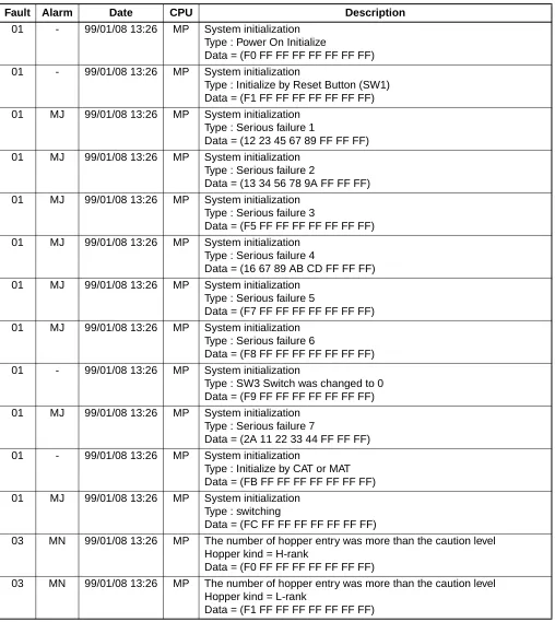
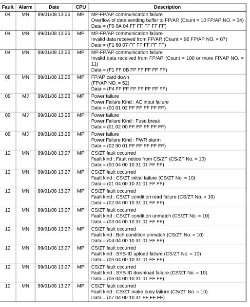
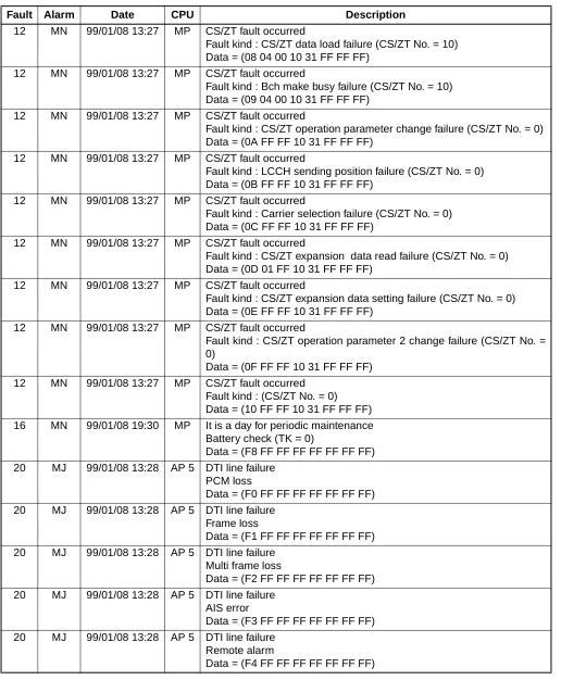
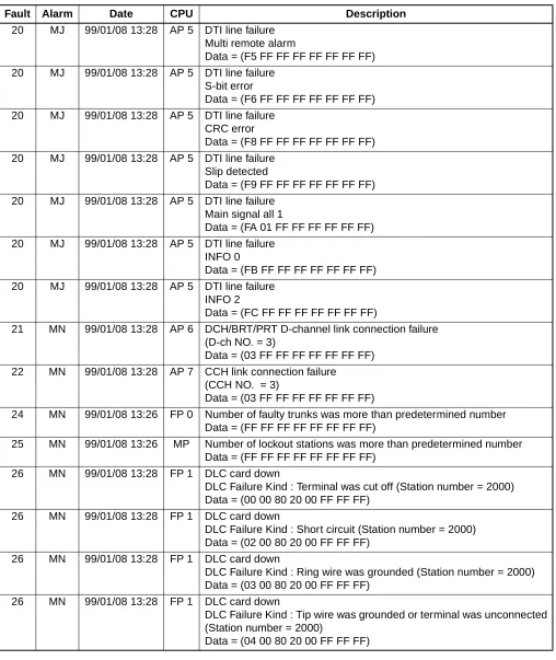
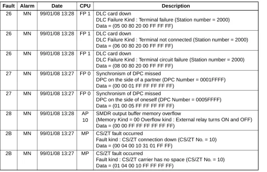
Table 1-5 provides an explanation of the 8-byte data that appears in the Description column.
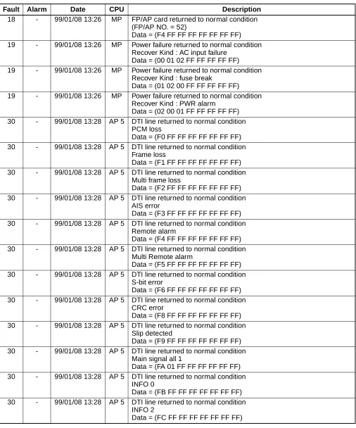
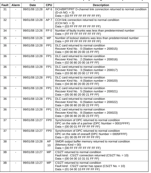
Table 1-7 shows examples of fault occurrence messages and Table 1-8 shows examples of
Table 1-7 Examples of Fault Occurrence Display Using MATWorX
Fault Alarm Date CPU Description
01 - 99/01/08 13:26 MP System initialization Type : Power On Initialize
Data = (F0 FF FF FF FF FF FF FF) 01 - 99/01/08 13:26 MP System initialization
Type : Initialize by Reset Button (SW1) Data = (F1 FF FF FF FF FF FF FF) 01 MJ 99/01/08 13:26 MP System initialization
Type : Serious failure 1
Data = (12 23 45 67 89 FF FF FF) 01 MJ 99/01/08 13:26 MP System initialization
Type : Serious failure 2
Data = (13 34 56 78 9A FF FF FF) 01 MJ 99/01/08 13:26 MP System initialization
Type : Serious failure 3
Data = (F5 FF FF FF FF FF FF FF) 01 MJ 99/01/08 13:26 MP System initialization
Type : Serious failure 4
Data = (16 67 89 AB CD FF FF FF) 01 MJ 99/01/08 13:26 MP System initialization
Type : Serious failure 5
Data = (F7 FF FF FF FF FF FF FF) 01 MJ 99/01/08 13:26 MP System initialization
Type : Serious failure 6
Data = (F8 FF FF FF FF FF FF FF) 01 - 99/01/08 13:26 MP System initialization
Type : SW3 Switch was changed to 0 Data = (F9 FF FF FF FF FF FF FF) 01 MJ 99/01/08 13:26 MP System initialization
Type : Serious failure 7
Data = (2A 11 22 33 44 FF FF FF) 01 - 99/01/08 13:26 MP System initialization
Type : Initialize by CAT or MAT Data = (FB FF FF FF FF FF FF FF) 01 MJ 99/01/08 13:26 MP System initialization
Type : switching
Data = (FC FF FF FF FF FF FF FF)
03 MN 99/01/08 13:26 MP The number of hopper entry was more than the caution level Hopper kind = H-rank
Data = (F0 FF FF FF FF FF FF FF)
03 MN 99/01/08 13:26 MP The number of hopper entry was more than the caution level Hopper kind = L-rank
04 MN 99/01/08 13:26 MP MP-FP/AP communication failure
Overflow of data sending buffer to FP/AP. (Count = 10 FP/AP NO. = 04) Data = (F0 0A 04 FF FF FF FF FF)
04 MN 99/01/08 13:26 MP MP-FP/AP communication failure
Invalid data received from FP/AP. (Count = 96 FP/AP NO. = 07) Data = (F1 60 07 FF FF FF FF FF)
04 MN 99/01/08 13:26 MP MP-FP/AP communication failure
Invalid data received from FP/AP. (Count = 100 or more FP/AP NO. = 11)
Data = (F1 FF 0B FF FF FF FF FF) 08 MN 99/01/08 13:26 MP FP/AP card down
(FP/AP NO. = 52)
Data = (F4 FF FF FF FF FF FF FF) 09 MJ 99/01/08 13:26 MP Power failure
Power Failure Kind : AC input failure Data = (00 01 02 FF FF FF FF FF) 09 MJ 99/01/08 13:26 MP Power failure
Power Failure Kind : Fuse break Data = (01 02 00 FF FF FF FF FF) 09 MJ 99/01/08 13:26 MP Power failure
Power Failure Kind : PWR alarm Data = (02 00 01 FF FF FF FF FF) 12 MN 99/01/08 13:27 MP CS/ZT fault occurred
Fault kind : Fault notice from CS/ZT (CS/ZT No. = 10) Data = (00 04 00 10 31 01 FF FF)
12 MN 99/01/08 13:27 MP CS/ZT fault occurred
Fault kind : CS/ZT initial failure (CS/ZT No. = 10) Data = (01 04 00 10 31 01 FF FF)
12 MN 99/01/08 13:27 MP CS/ZT fault occurred
Fault kind : CS/ZT condition read failure (CS/ZT No. = 10) Data = (02 04 00 10 31 01 FF FF)
12 MN 99/01/08 13:27 MP CS/ZT fault occurred
Fault kind : CS/ZT condition unmatch (CS/ZT No. = 10) Data = (03 04 00 10 31 01 FF FF)
12 MN 99/01/08 13:27 MP CS/ZT fault occurred
Fault kind : Bch condition unmatch (CS/ZT No. = 10) Data = (04 04 00 10 31 01 FF FF)
12 MN 99/01/08 13:27 MP CS/ZT fault occurred
Fault kind : SYS-ID upload failure (CS/ZT No. = 10) Data = (05 04 00 10 31 01 FF FF)
12 MN 99/01/08 13:27 MP CS/ZT fault occurred
Fault kind : SYS-ID download failure (CS/ZT No. = 10) Data = (06 04 00 10 31 01 FF FF)
12 MN 99/01/08 13:27 MP CS/ZT fault occurred
Fault kind : CS/ZT make busy failure (CS/ZT No. = 10) Data = (07 04 00 10 31 FF FF FF)
Table 1-7 Examples of Fault Occurrence Display Using MATWorX (Continued)
12 MN 99/01/08 13:27 MP CS/ZT fault occurred
Fault kind : CS/ZT data load failure (CS/ZT No. = 10) Data = (08 04 00 10 31 FF FF FF)
12 MN 99/01/08 13:27 MP CS/ZT fault occurred
Fault kind : Bch make busy failure (CS/ZT No. = 10) Data = (09 04 00 10 31 FF FF FF)
12 MN 99/01/08 13:27 MP CS/ZT fault occurred
Fault kind : CS/ZT operation parameter change failure (CS/ZT No. = 0) Data = (0A FF FF 10 31 FF FF FF)
12 MN 99/01/08 13:27 MP CS/ZT fault occurred
Fault kind : LCCH sending position failure (CS/ZT No. = 0) Data = (0B FF FF 10 31 FF FF FF)
12 MN 99/01/08 13:27 MP CS/ZT fault occurred
Fault kind : Carrier selection failure (CS/ZT No. = 0) Data = (0C FF FF 10 31 FF FF FF)
12 MN 99/01/08 13:27 MP CS/ZT fault occurred
Fault kind : CS/ZT expansion data read failure (CS/ZT No. = 0) Data = (0D 01 FF 10 31 FF FF FF)
12 MN 99/01/08 13:27 MP CS/ZT fault occurred
Fault kind : CS/ZT expansion data setting failure (CS/ZT No. = 0) Data = (0E FF FF 10 31 FF FF FF)
12 MN 99/01/08 13:27 MP CS/ZT fault occurred
Fault kind : CS/ZT operation parameter 2 change failure (CS/ZT No. = 0)
Data = (0F FF FF 10 31 FF FF FF) 12 MN 99/01/08 13:27 MP CS/ZT fault occurred
Fault kind : (CS/ZT No. = 0) Data = (10 FF FF 10 31 FF FF FF) 16 MN 99/01/08 19:30 MP It is a day for periodic maintenance
Battery check (TK = 0)
Data = (F8 FF FF FF FF FF FF FF) 20 MJ 99/01/08 13:28 AP 5 DTI line failure
PCM loss
Data = (F0 FF FF FF FF FF FF FF) 20 MJ 99/01/08 13:28 AP 5 DTI line failure
Frame loss
Data = (F1 FF FF FF FF FF FF FF) 20 MJ 99/01/08 13:28 AP 5 DTI line failure
Multi frame loss
Data = (F2 FF FF FF FF FF FF FF) 20 MJ 99/01/08 13:28 AP 5 DTI line failure
AIS error
Data = (F3 FF FF FF FF FF FF FF) 20 MJ 99/01/08 13:28 AP 5 DTI line failure
Remote alarm
Data = (F4 FF FF FF FF FF FF FF)
Table 1-7 Examples of Fault Occurrence Display Using MATWorX (Continued)
20 MJ 99/01/08 13:28 AP 5 DTI line failure Multi remote alarm
Data = (F5 FF FF FF FF FF FF FF) 20 MJ 99/01/08 13:28 AP 5 DTI line failure
S-bit error
Data = (F6 FF FF FF FF FF FF FF) 20 MJ 99/01/08 13:28 AP 5 DTI line failure
CRC error
Data = (F8 FF FF FF FF FF FF FF) 20 MJ 99/01/08 13:28 AP 5 DTI line failure
Slip detected
Data = (F9 FF FF FF FF FF FF FF) 20 MJ 99/01/08 13:28 AP 5 DTI line failure
Main signal all 1
Data = (FA 01 FF FF FF FF FF FF) 20 MJ 99/01/08 13:28 AP 5 DTI line failure
INFO 0
Data = (FB FF FF FF FF FF FF FF) 20 MJ 99/01/08 13:28 AP 5 DTI line failure
INFO 2
Data = (FC FF FF FF FF FF FF FF)
21 MN 99/01/08 13:28 AP 6 DCH/BRT/PRT D-channel link connection failure (D-ch NO. = 3)
Data = (03 FF FF FF FF FF FF FF) 22 MN 99/01/08 13:28 AP 7 CCH link connection failure
(CCH NO. = 3)
Data = (03 FF FF FF FF FF FF FF)
24 MN 99/01/08 13:26 FP 0 Number of faulty trunks was more than predetermined number Data = (FF FF FF FF FF FF FF FF)
25 MN 99/01/08 13:26 MP Number of lockout stations was more than predetermined number Data = (FF FF FF FF FF FF FF FF)
26 MN 99/01/08 13:28 FP 1 DLC card down
DLC Failure Kind : Terminal was cut off (Station number = 2000) Data = (00 00 80 20 00 FF FF FF)
26 MN 99/01/08 13:28 FP 1 DLC card down
DLC Failure Kind : Short circuit (Station number = 2000) Data = (02 00 80 20 00 FF FF FF)
26 MN 99/01/08 13:28 FP 1 DLC card down
DLC Failure Kind : Ring wire was grounded (Station number = 2000) Data = (03 00 80 20 00 FF FF FF)
26 MN 99/01/08 13:28 FP 1 DLC card down
DLC Failure Kind : Tip wire was grounded or terminal was unconnected (Station number = 2000)
Data = (04 00 80 20 00 FF FF FF)
Table 1-7 Examples of Fault Occurrence Display Using MATWorX (Continued)
26 MN 99/01/08 13:28 FP 1 DLC card down
DLC Failure Kind : Terminal failure (Station number = 2000) Data = (05 00 80 20 00 FF FF FF)
26 MN 99/01/08 13:28 FP 1 DLC card down
DLC Failure Kind : Terminal not connected (Station number = 2000) Data = (06 00 80 20 00 FF FF FF)
26 MN 99/01/08 13:28 FP 1 DLC card down
DLC Failure Kind : Terminal circuit failure (Station number = 2000) Data = (08 00 80 20 00 FF FF FF)
27 MN 99/01/08 13:27 FP 0 Synchronism of DPC missed
DPC on the side of a partner (DPC Number = 0001FFFF) Data = (00 00 01 FF FF FF FF FF)
27 MN 99/01/08 13:27 FP 0 Synchronism of DPC missed
DPC on the side of oneself (DPC Number = 0005FFFF) Data = (01 00 05 FF FF FF FF FF)
28 MN 99/01/08 13:28 AP 10
SMDR output buffer memory overflow
(Memory Kind = 00 Overflow kind : External relay turns ON and OFF) Data = (00 00 FF FF FF FF FF FF)
2B MN 99/01/08 13:27 MP CS/ZT fault occurred
Fault kind : CS/ZT connection down (CS/ZT No. = 10) Data = (00 04 00 10 31 01 FF FF)
2B MN 99/01/08 13:27 MP CS/ZT fault occurred
Fault kind : CS/ZT carrier has no space (CS/ZT No. = 10) Data = (01 04 00 10 FF FF FF FF)
Table 1-7 Examples of Fault Occurrence Display Using MATWorX (Continued)
Table 1-8 Example of Fault Restoration Display Using MATWorX
Fault Alarm Date CPU Description
18 - 99/01/08 13:26 MP FP/AP card returned to normal condition (FP/AP NO. = 52)
Data = (F4 FF FF FF FF FF FF FF) 19 - 99/01/08 13:26 MP Power failure returned to normal condition
Recover Kind : AC input failure Data = (00 01 02 FF FF FF FF FF) 19 - 99/01/08 13:26 MP Power failure returned to normal condition
Recover Kind : fuse break
Data = (01 02 00 FF FF FF FF FF) 19 - 99/01/08 13:26 MP Power failure returned to normal condition
Recover Kind : PWR alarm
Data = (02 00 01 FF FF FF FF FF) 30 - 99/01/08 13:28 AP 5 DTI line returned to normal condition
PCM loss
Data = (F0 FF FF FF FF FF FF FF) 30 - 99/01/08 13:28 AP 5 DTI line returned to normal condition
Frame loss
Data = (F1 FF FF FF FF FF FF FF) 30 - 99/01/08 13:28 AP 5 DTI line returned to normal condition
Multi frame loss
Data = (F2 FF FF FF FF FF FF FF) 30 - 99/01/08 13:28 AP 5 DTI line returned to normal condition
AIS error
Data = (F3 FF FF FF FF FF FF FF) 30 - 99/01/08 13:28 AP 5 DTI line returned to normal condition
Remote alarm
Data = (F4 FF FF FF FF FF FF FF) 30 - 99/01/08 13:28 AP 5 DTI line returned to normal condition
Multi Remote alarm
Data = (F5 FF FF FF FF FF FF FF) 30 - 99/01/08 13:28 AP 5 DTI line returned to normal condition
S-bit error
Data = (F6 FF FF FF FF FF FF FF) 30 - 99/01/08 13:28 AP 5 DTI line returned to normal condition
CRC error
Data = (F8 FF FF FF FF FF FF FF) 30 - 99/01/08 13:28 AP 5 DTI line returned to normal condition
Slip detected
Data = (F9 FF FF FF FF FF FF FF) 30 - 99/01/08 13:28 AP 5 DTI line returned to normal condition
Main signal all 1
Data = (FA 01 FF FF FF FF FF FF) 30 - 99/01/08 13:28 AP 5 DTI line returned to normal condition
INFO 0
Data = (FB FF FF FF FF FF FF FF) 30 - 99/01/08 13:28 AP 5 DTI line returned to normal condition
INFO 2
31 - 99/01/08 13:28 AP 6 DCH/BRT/PRT D-channel link connection returned to normal condition (D-ch NO. = 3)
Data = (03 FF FF FF FF FF FF FF)
32 - 99/01/08 13:28 AP 7 CCH link connection returned to normal condition (CCH NO. = 3)
Data = (03 FF FF FF FF FF FF FF)
34 - 99/01/08 13:26 FP 0 Number of faulty trunks was less than predetermined number Data = (FF FF FF FF FF FF FF FF)
35 - 99/01/08 13:26 MP Number of lockout stations was less than predetermined number Data = (FF FF FF FF FF FF FF FF)
36 - 99/01/08 13:28 FP1 DLC card returned to normal condition
Recover Kind No. : 0 (Station number = 200015) Data = (00 00 80 20 00 15 FF FF)
36 - 99/01/08 13:28 FP1 DLC card returned to normal condition
Recover Kind No. : 2 (Station number = 200016) Data = (02 00 80 20 00 16 FF FF)
36 - 99/01/08 13:28 FP1 DLC card returned to normal condition
Recover Kind No. : 3 (Station number = 200017) Data = (03 00 80 20 00 17 FF FF)
36 - 99/01/08 13:28 FP1 DLC card returned to normal condition
Recover Kind No. : 4 (Station number = 200020) Data = (04 00 80 20 00 20 FF FF)
36 - 99/01/08 13:28 FP1 DLC card returned to normal condition
Recover Kind No. : 5 (Station number = 200021) Data = (05 00 80 20 00 21 FF FF)
36 - 99/01/08 13:28 FP1 DLC card returned to normal condition
Recover Kind No. : 6 (Station number = 200022) Data = (06 00 80 20 00 22 FF FF)
36 - 99/01/08 13:28 FP1 DLC card returned to normal condition
Recover Kind No. : 8 (Station number = 200023) Data = (08 00 80 20 00 23 FF FF)
37 - 99/01/08 13:27 FP0 Synchronism of DPC returned to normal condition DPC on the side of a partner (DPC Number = 0001FFFF) Data = (00 00 01 FF FF FF FF FF)
37 - 99/01/08 13:27 FP0 Synchronism of DPC returned to normal condition DPC on the side of oneself (DPC Number = 0005FFFF) Data = (01 00 05 FF FF FF FF FF)
38 - 99/01/08 13:28 AP 10
SMDR output buffer memory returned to normal condition (Memory Kind = 00)
Data = (00 FF FF FF FF FF FF FF) 3B - 99/01/08 13:27 MP CS/ZT returned to normal condition
Fault kind : CS/ZT connection returned (CS/ZT No. = 10) Data = (00 04 00 10 31 01 FF FF)
3B - 99/01/08 13:27 MP CS/ZT returned to normal condition
Fault kind : CS/ZT carrier has space (CS/ZT No. = 10) Data = (01 04 00 10 FF FF FF FF)
Table 1-8 Example of Fault Restoration Display Using MATWorX (Continued)
STATION LINE STATUS DISPLAY
General Description
This feature displays the line status for a single line telephone or a Dterm using the CAT or the MAT.
Service Conditions
(1) This feature is not available when the system is off-line.
(2) When performing this feature for a single line telephone, this feature may affect the status of the other telephone in the same line circuit card. Therefore, use this feature only when a line fault has occurred (do not use under a normal state).
Programming Procedure
No programming is required.
Operating Procedure
Operation:
Explanation of Screen Information:
Station Number: X-XXXXXXXX (1-8 digits) EC1 + DE EC1>
ST COMMAND=
X-XXXXXXXX + DE XXXXXXXX : XX XX XX (Station No.)
XXXXXXXX : XX XX XX
4 2
1 3
Analog Line/Digital Line
00: LC (Single Line Telephone) 10: DLC (Dterm)
Hardware Test See Table 1-9.
Software Test
01 - FF: See Table 1-10. (This data is the same as the status code of CMF5.)
Table 1-9 Status of Single Line Telephone and Dterm
INDICATION STATUS OF SINGLE
LINE TELEPHONE STATUS OF Dterm REMARKS
00 Terminal is not connected. Terminal is not connected, or Tip wire is grounded.
01 Terminal is connected. Terminal is connected. 02 Loop (Short circuit is made
on the line.)
Short circuit is made on the line.
03 Ring wire is grounded Ring wire is grounded. 04 LC card is not mounted. DLC card is not mounted.
05 Test busy Terminal Failure
06 – DLC card down
07 – –
08 – Line failure detected
2
3
BATTERY RELEASE CONTROL
General Description
When the AC power is to be cut off intentionally (such as maintenance for the building), this fea-ture can disconnect the batteries from the PBX, using the MAT or the CAT, and prevent an exces-sive discharge of the battery.
Figure 1-1 System Diagram of Battery Release Control
Service Conditions
The battery disconnection is canceled if the system is initialized (Power off/on or Reset).
Programming Procedure
No programming is required.
MAT MODEM
C.O. NETWORK
ENTERING COMMAND PBX
MODEM
MP
BATTERY CONNECTION RELAY PWR
Operating Procedure
(1) To disconnect the battery
(2) To cancel the battery disconnection DE
+ EC0>
EC0
ST COMMAND=
DE
+ EC0>00:1 – 00
EXE
+ EC0>00:1 – 0 0
OK
The current status displays after entering first data 00 (1: Battery connection)
The status changes to battery disconnection after entering second data 0.
DE
+ EC0>
EC0
ST COMMAND=
DE
+ EC0>00:0 – 00
EXE
+ EC0>00:0 – 1 1
OK
The current status displays after entering first data 00 (0: Battery disconnection)
STATION/TRUNK STATUS DISPLAY
General Description
This feature allows station/trunk connection status to be displayed on the MAT. If the status is ab-normal, this feature can forcibly release the connection using the MOC Terminal feature of MAT-WorX or the CAT.
Service Conditions
(1) Printout of connection status or execution report of forced release is available through the printer connected to the MAT.
(2) This feature is available for the following items:
• Trunk number (analog trunks) • Station number
• Virtual station number (Except for Intercom/Attendant position loop line.)
Programming Procedure
No programming is required.
Operating Procedure
(1) To display Station/Trunk Status:
Refer to the MATWorX Studio User’s Guide.
(2) To forcibly release the station/trunk connection:
Operation:
DE
+ EB0>
EB0
ST COMMAND=
DE
+ XXX : CCC
DXXX
(Trunk No.)
Trunk No.
DE
+ EB2>
EB2
ST COMMAND=
DE
+ XXXXXXXX : CCC
X-XXXXXXXX
(Station No.) FX-FXXXXXXXX
DIAGNOSTICS
General Description
To assist maintenance personnel, this feature provides diagnostic capabilities such as fault code generation, device status information and alarm information recording, which can be accessed from the MAT or the CAT.
Service Conditions
(1) The following station status information can be displayed on the MAT or the CAT by direct command:
• Idle
• Line Lockout • Dialing
• Tone Trunk Connection (reorder tone, busy tone, service set tone, etc.)
• Types of Connection (station-to-station, three-way calling, voice calling, holding, etc.) • Destination number (trunk number, register number)
• Short circuit on line
(2) The following trunk status information can be displayed on the MAT or the CAT by direct command:
• Idle
• Ringing in
• Incoming queue to Attendant Console • Holding
• In a tandem connection • Incoming queue to UCD • Dialing
(3) The following information is stored and can be displayed on the MAT or the CAT using a memory dump command in hexadecimal format:
• Program address where an endless loop has occurred • Last initialization time for main program
• Last initialization time for firmware program
• The reason for initialization (power-on, RESET key, endless loop, rotary switch, command from MAT or CAT)
(4) The PBX has a built-in patrol program that monitors the status of all connected devices. Additionally, when no response or an invalid response from a device is received, this program stores in memory the slot number of that device. From the MAT or the CAT, a maintenance person can read the slot number of any device that does not respond to the main processor or provides an illegal status to the main processor.
Programming Procedure
No programming is required.
Operating Procedure
(1) Station Status Information
Operation:
For the meaning of status code, see Table 1-10. DE
+ F50> F50
ST COMMAND=
DE
+ XXXX : XX XX XX XX 0 + X-XXXXXXXX
(Station No.) or
0 + FX-FXXXXXXXX
(Dterm No.) Status Code of the designated Address +3 Status Code of the designated Address +2
Status Code of the designated Address +1
Status Code of the designated Address
Table 1-10 Station Status Information
STATUS
CODE DESCRIPTION REMARKS
01 Idle
02 In Line Lockout mode
10 Dialing to an ORT
11 Dialing to a trunk
12 Dialing to an ORT (After consultation hold a station) 13 Dialing to an ORT (After consultation hold a trunk) 14 Dialing to a trunk (After consultation hold a station) 15 Dialing to a trunk (After consultation hold a trunk)
1F Dialing to an ORT (After consultation hold 3 party Confer-ence Trunk)
20 In Reorder Tone connection
21 In Reorder Tone connection (While consultation hold a Station)
22 In Reorder Tone connection (While consultation hold a trunk) 23 In Reorder Tone connection (While consultation hold 3 party
Conference Trunk)
2C In Howler Tone connection 30 In Service Set tone connection
32 In Service Set tone connection (While consultation hold a trunk)
40 In Ringback Tone Connection
41 In Ringback Tone Connection for the second call (After consultation hold a station)
42 In Ringback Tone connection for the second call (After consultation hold a trunk)
44 In Ringback Tone connection for the operator call 45 In Ringback Tone connection for operator call
NOTE: The status codes not described in this table mean busy conditions. 46 In Ringback Tone connection for operator call
(After consultation hold a trunk) 50 Ringing (Call from a station)
51 Ringing (Call from an outside party) 55 Ringing (Automatic Wake Up Call) 60 In Station to Station connection 62 In 3 Way Calling
65 Holding
66 Voice Call to a Dterm
67 Voice Call from a Station 71 In Station to Trunk connection
72 Three-way calling with a station and a trunk C4 In a CAT mode (For Dterm)
C8 In a UCD Queue
C9 In a UCD Queue after holding a station CA In a UCD Queue after holding a trunk
Table 1-10 Station Status Information (Continued)
STATUS
(2) Trunk Status Information
Operation:
For the meaning of status code, see Table 1-11. DE
+ F50>
F50
ST COMMAND=
DE
+ XXXX : XX XX XX XX 0 + DXXX
(Trunk No.)
Status Code of the designated Address +3
Status Code of the designated Address +2
Status Code of the designated Address +1
Status Code of the designated Address
Table 1-11 Trunk Status Information
STATUS
CODE DESCRIPTION REMARKS
01 Incoming queue to Attendant Console
03 Attendant Camp On
04 In a trunk to station connection 05 Dialing In (Tie Line)
06 In a tandem connection
08 Hold by Exclusive/Nonexclusive Hold
09 TAS in progress
0A Incoming queue to UCD
0B Threeway Calling with a station and two trunks 0D In Ringback Tone/Busy Tone connection (Tie Line) 0E Waiting for release signal from distant office
10 Sending dialed digits (Outgoing Trunk of a tandem connection)
11 Threeway calling with two stations
14 Dialing In (Incoming Trunk of a trunk to trunk connection) 19 Ringing In (Trunk Direct Appearance on Dterm)
1A Ringing In (Direct In Termination-DIT)
1B Ringing In (Trunk Direct Appearance and DIT) 20 Holding by Call Hold
21 Holding by Call Park
2A Incoming Queue to UCD (While sending message) 2B Incoming Queue to UCD (After sending message)
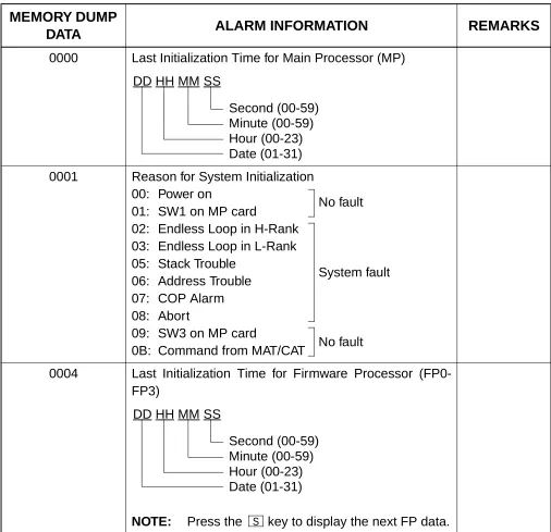
(3) Alarm Information
Operation:
DE
+ F53>
F53
ST COMMAND=
DE
+ XXXX : XX XX XX XX XXXX
(Memory Dump Data)
Table 1-12 Alarm Information
MEMORY DUMP
DATA ALARM INFORMATION REMARKS
0000 Last Initialization Time for Main Processor (MP)
0001 Reason for System Initialization 00: Power on
01: SW1 on MP card
02: Endless Loop in H-Rank 03: Endless Loop in L-Rank 05: Stack Trouble
06: Address Trouble 07: COP Alarm 08: Abort
09: SW3 on MP card
0B: Command from MAT/CAT
0004 Last Initialization Time for Firmware Processor (FP0-FP3)
NOTE: Press the key to display the next FP data.
DD HH MM SS
Second (00-59) Minute (00-59) Hour (00-23) Date (01-31)
No fault
System fault
No fault
DD HH MM SS
Second (00-59) Minute (00-59) Hour (00-23) Date (01-31)
BATTERY REPLACEMENT
The interval of battery replacement depends on the ambient temperature.
The following caution label, which is attached to the reverse side of the Front Cover for PIM and BATTM, shows battery replacement intervals.
When you set up the battery for the first time, record the installation date. Refer to the BATTERY REPLACEMENT TABLE for the recommended periods to replace the battery.
0 ~ 50°C
2 YEARS
(AVERAGE 25°C)
BATTERY REPLACEMENT TABLE
INSTALLATION DATE:
AMBIENT TEMPERATURE
5 ~ 35°C
(AVERAGE 25°C)
REPLACEMENT
INTERVAL 3 YEARS 1 YEAR
CAUTION
TO PREVENT INJURY AND SKIN BURN,PAY ATTENTION TO THE FOLLOWING.o DO NOT STRIKE A MATCH OR CAUSE A SPARK IN VICINITY OF BATTERY.
o PLACE THE EQUIPMENT IN WELL VENTILATED AREA.
o DO NOT SHORT.
o REPLACE BATTERY ONLY AFTER BATTERY GASES HAVE BEEN DISPERSED.
o ELECTROLYTE LEAKAGE OR OTHER HAZARDS MAY RESULT IF THE BATTERY IS NOT REPLACED IN ACCORDANCE WITH THE SPECIFIED INTER-VALS.
(AVERAGE 40°C)
PERIODIC ALARM
General Description
This feature can indicate the alarm on the Dterm function key or external alarm display panel for periodic inspection.
The PBX controls the time of periodic inspection, and when the time (assigned by CM43 Y=2) comes, indicates the alarm.
Figure 1-2 Periodic Alarm Indications
Service Conditions
(1) Use CM43 Y=2 to assign the time (year, month, date, time) of periodic inspection; for example, battery exchange.
(2) When the time of periodic inspection comes, the Dterm alarm function key lights when the setting is the MJ alarm, or flashes with 60 IPM when the setting is the MN alarm. At the same time, the alarm display panel can indicate the alarm.
(3) Up to two Dterms in a system can indicate the periodic alarm.
(4) The alarm indication can be cleared by assigning CMEA Y=1 from CAT/MAT. MP
PBX panel
MJ MN
Feature
4 5
6
GHI JKL
7 8
9
PQRS TUV
0 #
O PER
1 2
3
ABC DEF
Record the time of periodic inspection
Programming Procedure
DESCRIPTION DATA
Assign the date and time setting for periodic alarm. • (1) (2) Y=2 00
YYYY MM DD HH
YYYY :1999-2050 (Year) MM :01-12 (Month) DD :01-31 (Date) HH :00-23 (Hour)
Assign the battery exchange to inspection kind. • (1) (2) Y=3 00
0 : Battery exchange alarm NONE :No Data
Specify the Dterm for alarm display. • (1)
(2) Y=16 01: Dterm 1 02: Dterm 2
X-XXXXXXXX (My line number of Dterm)
NONE :No Data
Assign the alarm indication key to Dterm function key.
•
(1)
(2) Y=00
My line number + +Key number (01-24)
F5020: Alarm display
Set the External Alarm Kind to MJ/ MN alarm. • (1) (2) Y=2 16
• To clear the alarm display
DESCRIPTION DATA
Clear the alarm display. •
Y=1
00: Clear both MJ/MN alarm 01: Clear MJ alarm
02: Clear MN alarm START
TROUBLESHOOTING
PRECAUTIONS
Procedure for Unplugging/Plugging Circuit Cards
When removing a circuit card from the PIM or when mounting a circuit card in the PIM, follow the procedure in Table 2-1.
Table 2-1 Procedure for Unplugging/Plugging Circuit Cards
CIRCUIT CARD PROCEDURE CONDITION PLUG UNPLUG
• PN-CP14 (MP)
• PZ-PW121 (AC/DC PWR)
• PZ-PW122 (DC/DC PWR)
• PZ-M537 (EXPMEM)
(1) Power off
(2) Plug in
(3) Power on
(1) Power off
(2) Unplug
(3) Power on
These circuit cards must be plugged in or unplugged only with power off to prevent damage to the card or other system circuitry.
• PN-AP00-A (DBM)
• PN-AP00-B (AP00)
• PN-AP01 (AP01)
• PN-BRTA (BRT)
• PN-2BRTC (BRT)
• PN-CP15 (FP)
• PN-24DTA-C (DTI)
• PN-30DTC-A (DTI)
• PN-24PRTA (PRT)
• PN-PW00 (EXTPWR)
• PN-4RSTB (MFR)
• PN-4RSTC (CIR)
• PN-SC00 (CCH)
• PN-SC01 (DCH)
• PN-SC03 (ICH)
• PN-SC03-A (CSH)
(1) Power off or MB switch on
(2) Plug in
(3) Power on or MB switch off
(1) Power off or MB switch on
(2) Unplug
(3) Power on
Static Electricity Guard
You must wear a grounded wrist strap to protect circuit cards from static electricity.
Figure 2-1 Static Electricity Guard (1 of 2)
• WHEN PLUGGING/UNPLUGGING A CIRCUIT CARD
• WHEN HOLDING A CIRCUIT CARD
PBX
WRIST STRAP
FRAME GROUND SCREW
CARD FRONT
Figure 2-1 Static Electricity Guard (2 of 2)
• WHEN MAKING A SWITCH SETTING ON A CIRCUIT CARD
• WHEN CARRYING A CIRCUIT CARD
WEAR A WRIST STRAP AND PERFORM THE WORK ON A GROUNDED
CONDUCTIVE WORK SURFACE. CIRCUIT
CARD
WHEN CARRYING A CIRCUIT CARD AROUND, KEEP THE CARD IN A CONDUCTIVE POLYETHYLENE BAG. CIRCUIT
CARD CONDUCTIVEPOLYETHYLENE
CAUTION
You must hold the edge of a circuit card when plugging or unplugging the circuit card. If you touch another area, you may be exposed to hazardous voltages.
CARD FRONT
NEVER TOUCH THE COMPONENTS OR SOLDERED SURFACE WITH BARE HANDS.
Turning Power ON
(1) Check the switch position of each PZ-PW121 card before turning power on.
• Make sure that the AC120V/240V selector switch is positioned to appropriate voltage for each country (AC120V or AC240V).
• Make sure that the battery mode selector switch is positioned as shown below to meet the kind of battery:
(2) Turn the SW1 switches of all the PZ-PW121 cards to ON. First, turn ON PIM1 to PIM7. Then, turn ON PIM0 last of all.
CAUTION
1. When the operating power is being supplied to the PZ-PW121 card, do not plug/unplug this circuit card into/from its mounting slot.
2. When the system is configured with two or more PIMs, the BUS cable provides gang control for the PZ-PW121 card of PIM0 and other PIMs. Therefore, if the power of PIM0 is off, no power is supplied to the whole system even when the power switch(es) of other PIMs are left on. Note, however, that the battery continues to charge even under these circumstances. 3. Do not turn off the PZ-PW121 card on PIM1 to PIM7 when the system is operating.
SW 240V 100V/120V
ON OFF
12
SW101
1 : Not used
2 : ON (SEAL/FLOAT2)
Turning Power OFF
(1) Before turning power off, make sure that all line/trunk cards are not operating by no busy lamps indication.
OUTLINE OF TROUBLESHOOTING
Figure 2-2 shows an outline of the recommended troubleshooting procedure.
Figure 2-2 Troubleshooting Outline
START
FAULT DIAGNOSIS AND TROUBLESHOOTING
Fault Detection Method (SeePage 59.) (1) Alarm Indication on PWRU, Alarm Display
Panel
(2) Lamp Indication on Circuit Cards (3) Complaint from station user or operator
Fault Diagnosis and Troubleshooting Method (1) Display on MAT/CAT (See Page 65.)
• Fault Message
• Station Line Status Display (2) Lamp Indication on Cards
(See Page 83.)
(3) Contents of complaint from station user or operator (See Page 95.)
FAULT DETECTION
FAULT DETECTION
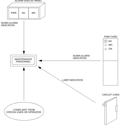
This section describes the way in which alarm indications are given. If a fault occurs in the sys-tem, you can detect the fault via the routes shown in Figure 2-3.
Figure 2-3 Alarm Indication Routes
PWR CARD
MJ
MN
ON
PWR MJ MN
ALARM DISPLAY PANEL
MJ/MN ALARM INDICATION
MJ/MN ALARM INDICATION
LAMP INDICATION
CIRCUIT CARD MAINTENANCE
PERSONNEL
(1) Fault Detection by Alarm Indication
When a fault occurs in the system, you can detect the fault by a Major (MJ) alarm or Minor (MN) alarm indicated on the AC/DC PWR card or by the external Alarm Display Panel.
(2) Fault Detection by Lamp Indication on Circuit Cards
When a fault occurs in the system, you can detect the fault by lamp indication on circuit cards, such as a Major (MJ) or Minor (MN) alarm indicated on the MP card. Table 2-2 iden-tifies the alarm indication lamps on each circuit card. For details of lamp indication on circuit cards, refer to the Installation Procedure Manual.
(3) Fault Detection by Complaint from Station User or Operator
Table 2-2 Lamp Indications on Circuit Cards
KIND OF
CIRCUIT CARD CARD NAME
LAMP
NAME COLOR
INDICATIONS
NORMAL ABNORMAL
Control Cards PN-CP14 (MP) RUN Green 120 IPM Flash Steady ON or OFF
PN-CP15 (FP) RUN Green 120 IPM Flash Steady ON or OFF PN-PW00
(EXTPWR)
RUN Green Steady ON OFF
PZ-PW121 (AC/DC PWR)
ON Green Steady ON OFF
PZ-PW122 (DC/DC PWR)
ON Green Steady ON OFF
Application Processor Cards
PN-AP00-A (DBM)
RUN Green 120 IPM Flash Steady ON or OFF
PN-AP00-B (AP00)
RUN Green 120 IPM Flash Steady ON or OFF
PN-AP01 (AP01)
RUN Green 120 IPM Flash Steady ON or OFF
PN-BRTA (BRT) RUN Green 120 IPM Flash Steady ON or OFF
ALM Red OFF Steady ON
PN-2BRTC (BRT)
RUN Green 120 IPM Flash Steady ON or OFF
ALM0 Red OFF Steady ON
ALM1 Red OFF Steady ON
PN-CC01 (ETHER)
RUN Green 60 IPM Flash Steady ON or OFF
PN-24DTA-C (DTI)
RUN Green 120 IPM Flash Steady ON or OFF
AIS Red OFF Steady ON
RMT Red OFF Steady ON
FRM Red OFF Steady ON
PCM Red OFF Steady ON
Application Processor Cards
PN-30DTC-A (DTI)
RUN Green 120 IPM Flash Steady ON or OFF
AIS Red OFF Steady ON
MRMT Red OFF Steady ON
RMT Red OFF Steady ON
MFRM Red OFF Steady ON
FRM Red OFF Steady ON
PCM Red OFF Steady ON
PN-24PRT (PRT)
RUN Green 120 IPM Flash Steady ON or OFF
LC Green Steady ON OFF
AIS Red OFF Steady ON
RMT Red OFF Steady ON
FRM Red OFF Steady ON
PCM Red OFF Steady ON
CRC Red OFF Steady ON
PN-4RSTB (MFR)
RUN Green 120 IPM Flash Steady ON or OFF
PN-4RSTC (CIR)
RUN Green 120 IPM Flash Steady ON or OFF
PN-SC00 (CCH) RUN Green 120 IPM Flash Steady ON or OFF
LC Green Steady ON OFF
PN-SC01 (DCH) RUN Green 120 IPM Flash Steady ON or OFF
LC Green Steady ON OFF
PN-SC03 (ICH) RUN Green 120 IPM Flash Steady ON or OFF
DOPE0 Green Steady ON OFF
DOPE1 Green Steady ON OFF
DOPE2 Green Steady ON OFF
DOPE3 Green Steady ON OFF
DOPE4 Green Steady ON OFF
DOPE5 Green Steady ON OFF
DOPE6 Green Steady ON OFF
DOPE7 Green Steady ON OFF
Table 2-2 Lamp Indications on Circuit Cards (Continued)
KIND OF
CIRCUIT CARD CARD NAME
LAMP
NAME COLOR
INDICATIONS
Application Processor Cards
PN-SC03-A (CSH)
RUN Green 120 IPM Flash Steady ON or OFF
DOPE0 Green Steady ON OFF
DOPE1 Green Steady ON OFF
DOPE2 Green Steady ON OFF
DOPE3 Green Steady ON OFF
DOPE4 Green Steady ON OFF
DOPE5 Green Steady ON OFF
DOPE6 Green Steady ON OFF
DOPE7 Green Steady ON OFF
Line /Trunk Cards PN-2COTD (COT)
[For Australia/ Others]
LF0 Red OFF Steady ON
LF1 Red OFF Steady ON
PN-4COTE (COT)
[For Australia]
LF0 Red OFF Steady ON
LF1 Red OFF Steady ON
LF2 Red OFF Steady ON
LF3 Red OFF Steady ON
PN-6COTJ (COT)
[For Australia]
LF0 Red OFF Steady ON
LF1 Red OFF Steady ON
LF2 Red OFF Steady ON
LF3 Red OFF Steady ON
LF4 Red OFF Steady ON
LF5 Red OFF Steady ON
Table 2-2 Lamp Indications on Circuit Cards (Continued)
KIND OF
CIRCUIT CARD CARD NAME
LAMP
NAME COLOR
INDICATIONS
Line/Trunk Cards PN-8COTT (COT)
[For Australia]
LF0 Red OFF Steady ON
LF1 Red OFF Steady ON
LF2 Red OFF Steady ON
LF3 Red OFF Steady ON
LF4 Red OFF Steady ON
LF5 Red OFF Steady ON
LF6 Red OFF Steady ON
LF7 Red OFF Steady ON
PN-2CSIA (CSI)
[For North America/ Latin America]
OPE Green Steady ON OFF
B12 Red ON/OFF 60 IPM Flash
B11 Red ON/OFF 60 IPM Flash
B10 Red ON/OFF 60 IPM Flash
B02 Red ON/OFF 60 IPM Flash
B01 Red ON/OFF 60 IPM Flash
B00 Red ON/OFF 60 IPM Flash
PN-2CSIA-A (CSI)
[For Australia/ Others]
OPE Green Steady ON OFF
B12 Red ON/OFF 60 IPM Flash
B11 Red ON/OFF 60 IPM Flash
B10 Red ON/OFF 60 IPM Flash
B02 Red ON/OFF 60 IPM Flash
B01 Red ON/OFF 60 IPM Flash
B00 Red ON/OFF 60 IPM Flash
PN-M03(M03) OPE Green Steady ON OFF
PN-M10(M10) CK0 Green Steady ON OFF
CK1 Green Steady ON OFF
TALM Red OFF Steady ON
RALM Red OFF Steady ON
Table 2-2 Lamp Indications on Circuit Cards (Continued)
KIND OF
CIRCUIT CARD CARD NAME
LAMP
NAME COLOR
INDICATIONS
FAULT DIAGNOSIS AND TROUBLESHOOTING
Display on MAT/CAT
When the MJ/MN alarm is on, you can diagnose the contents of the fault by the Fault Message and the Station Line Status Display features, which are displayed on the MAT or the CAT, and restore the fault.
FAULT MESSAGE
Item (1) shows the display format for the Fault Message feature, and item (2) shows the fault di-agnosis and troubleshooting method. For details of the Fault Message feature, see "Fault Mes-sages" on Page 5.
(1) Display Format
1: 01 MN MP 00
2: 99/10/24 20:31
3: X X X X X X X X
CPU Kind and No. that detected the fault MP 00 : MP
FP 00-03 : FP No. 0-3 AP 04-15, 20-31 : AP No. 4-15, 20-31
Alarm Kind (MJ/MN/–)
Fault Occurrence Kind No./Fault Restoration Kind No.
Date and Time of Fault Occurrence and Restoration
Fault Information/
Fault Restoration Information
(For details, see Table 2-3 and Table 2-4.)
4: X X X X X X X X
Fault Information/
Fault Restoration Information
(For details, see Table 2-3 and Table 2-4.) 1st Screen
2nd Screen
3rd Screen
(2) Fault Diagnosis and Troubleshooting
Table 2-3 shows the fault information and the remedial action on each fault kind. Table 2-4
shows the fault restoration information on each fault restoration kind. Diagnose contents of the fault and perform the remedial action listed in Table 2-3.
Table 2-3 Remedial Action on Each Fault Kind
FAULT KIND NUMBER
FAULT
CONTENT FAULT INFORMATION REMEDIAL ACTION
01 System initialized 3: XX XX XX XX 4: XX XX XX XX
Kind of System Initialization related information
1: Program address information
2: Receive command information
F: No system initialization related information Initial Kind (See below.) The address of the program which caused system
initialization
Initial Kind 0: Power On Initialize No specific action is required.
Initial Kind 1: Initialize by Reset Button (SW1)
Initial Kind 2: Serious failure 1 Replace the MP card. Initial Kind 3: Serious failure 2 Replace the MP card. Initial Kind 5: Serious failure 3 Replace the MP card. Initial Kind 6: Serious failure 4 Replace the MP card. Initial Kind 7: Serious failure 5 Replace the MP card. Initial Kind 8: Serious failure 6 Replace the MP card. Initial Kind 9: SW3 was changed
to 0
No specific action is required.
Initial Kind A: Serious failure 7 Replace the MP card. Initial Kind B: Initialize by CAT/MAT No specific action is
required.
1 2 3
3 1
04 MP-FP/AP commu-nication failure
3: XX XX XX XX
Communication Failure Kind 00: Overflow of data sending
buffer to the FP/AP
01: Invalid data received from FP/AP
Number of communication failures
FP/AP Number 00-03: FP No. 0-3
04-15: AP No. 4-15, 20-31
Replace the corre-sponding FP or AP card indicated in the FP/AP Number.
08 FP/AP card down 3: XX XX XX XX
FP/AP Number
00-03 :FP No. 0-3
015, 20-31 :AP No. 4-15, 20-31
Replace the corre-sponding FP or AP card indicated in the FP/AP Number.
09 Power failure 3: XX XX XX XX
Power Failure Kind (See below.) Power Failure Kind 00: AC input
failure
Check to see if the AC power source is cut off or the plug is discon-nected.
Power Failure Kind 01: Fuse break Check for a break in the battery fuse. Power Failure Kind 02: PWR alarm Check the output
voltage of the PWR card.
Replace the PWR card.
Table 2-3 Remedial Action on Each Fault Kind (Continued)
FAULT KIND NUMBER
FAULT
CONTENT FAULT INFORMATION REMEDIAL ACTION
1 2 3 1
2
3
1