OCTOBER, 2000
NEC America, Inc.
STOCK # 200773Installation Manual
NEC America, Inc. reserves the right to change the specifications, functions, or features, at any time, without notice.
NEC America, Inc. has prepared this document for use by its employees and customers. The information contained herein is the property of NEC America, Inc. and shall not be reproduced without prior written approval from NEC America, Inc.
NEAX® and Dterm® are registered trademarks of NEC Corporation. Copyright 2000
NEC America, Inc.
ISSUE 1 ISSUE 2 ISSUE 3 ISSUE 4
DATE OCTOBER, 2000 DATE DATE DATE
ISSUE 5 ISSUE 6 ISSUE 7 ISSUE 8
DATE DATE DATE DATE
ISSUE 1 ISSUE 2 ISSUE 3 ISSUE 4
DATE OCTOBER, 2000 DATE DATE DATE
ISSUE 1 ISSUE 2 ISSUE 3 ISSUE 4
DATE OCTOBER, 2000 DATE DATE DATE
ISSUE 5 ISSUE 6 ISSUE 7 ISSUE 8
DATE DATE DATE DATE
ISSUE 1 ISSUE 2 ISSUE 3 ISSUE 4
DATE OCTOBER, 2000 DATE DATE DATE
ISSUE 1 ISSUE 2 ISSUE 3 ISSUE 4
DATE OCTOBER, 2000 DATE DATE DATE
ISSUE 5 ISSUE 6 ISSUE 7 ISSUE 8
DATE DATE DATE DATE
ISSUE 1 ISSUE 2 ISSUE 3 ISSUE 4
DATE OCTOBER, 2000 DATE DATE DATE
361 1
362 1
363 1
364 1
365 1
366 1
367 1
368 1
369 1
370 1
371 1
372 1
373 1
374 1
375 1
376 1
377 1
378 1
379 1
380 1
381 1
OCTOBER, 2000
NEAX2400 IPX
Installation Manual
TABLE OF CONTENTS
Page
LIST OF FIGURES . . . vii
LIST OF TABLES . . . .xiii
SAFETY CONSIDERATIONS. . . xv
REGULATORY INFORMATION . . . xvii
1. REGULATORY REQUIREMENTS . . . xvii
2. FCC PART 15 REQUIREMENTS . . . xvii
3. FCC PART 68 REGISTRATION . . . xvii
3.1 Company Notification. . . xvii
3.2 Service Requirements . . . xviii
3.3 Location of FCC Compliance Labels . . . xviii
4. DIRECT-INWARD DIALING (DID) CALLS . . . xviii
5. REGULATORY INFORMATION ON SINGLE-LINE ANALOG TELEPHONES. . . xix
6. HEARING AID COMPATIBILITY . . . xix
7. INDUSTRY CANADA CS-03 . . . xix
8. SAFETY LISTING/CERTIFICATIONS . . . xx
8.1 Safety Considerations . . . xx
CHAPTER 1 INTRODUCTION . . . 1
1. GENERAL . . . 1
2. HOW TO FOLLOW THE MANUAL. . . 1
2.1 Outline . . . 1
2.2 How to Follow NAPs . . . 2
2.3 How To Follow Trees . . . 4
2.4 Figure and Table Numbers. . . 6
2.5 Essential/Critical Information . . . 6
CHAPTER 2 INSTALLATION DESIGN . . . 7
1. GENERAL . . . 7
2. ENVIRONMENTAL REQUIREMENTS. . . 7
2.1 Temperature And Humidity . . . 7
2.2 Heat Generation From Switching Equipment. . . 8
3. FLOOR SPACE . . . 9
4. FLOOR LOAD REQUIREMENTS . . . 9
Page
5.1 Floor Surface . . . 9
5.2 Wall . . . 10
5.3 Ceiling . . . 10
5.4 Lighting Facilities . . . 10
6. POWER SUPPLY REQUIREMENTS . . . 10
6.1 Main Source Power . . . 10
6.2 Current Consumption. . . 11
6.3 Power Distribution Box Requirements . . . 12
6.4 Grounding . . . 12
7. MDF REQUIREMENTS . . . 12
8. INSTALLATION TOOLS . . . 13
9. SYSTEM ACCOMMODATION . . . 14
9.1 Port Interface Module Configuration and Conditions for Configuration . . . 14
9.2 Circuit Card Locations . . . 22
9.3 Preparation Of Trunking Diagram . . . 26
9.4 Preparation Of Module Group Face Layout And Port Accommodation Diagram . . . 26
9.5 Preparation Of Circuit Card Switch Setting Sheets . . . 26
10. INSTALLATION CABLES . . . 26
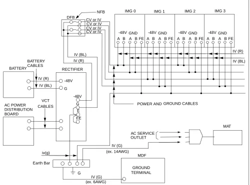
10.1 AC Input, DC Power, And Ground Cables . . . 27
10.2 Cables Between The PBX And MDF . . . 33
CHAPTER 3 INSTALLATION PROCEDURE . . . . 35
1. GENERAL . . . 35
2. PRECAUTIONS BEFORE BEGINNING INSTALLATION. . . 36
2.1 Outline . . . 36
3. INSTALLATION PROCEDURE. . . 38
NAP-200-001. Installation Preparation . . . 39
NAP-200-002. Marketing, Leveling, and Drilling . . . 41
1. WHEN SECURING THE PBX DIRECTLY ONTO THE FLOOR . . . 42
2. WHEN SECURING THE PBX WITH THE SPECIAL STAND . . . 45
3. WHEN SECURING PBX WITH FLOOR ELEVATIONS . . . 47
4. MARKING, LEVELING AND DRILLING FOR MDF, POWER EQUIPMENT, AND PERIPHERAL EQUIPMENT . . . 48
NAP-200-003. Unpacking and Inspection. . . 49
1. UNPACKING. . . 49
2. INSPECTION . . . 50
NAP-200-004. Installation of the Base Unit . . . 51
1. INSTALLING THE BASE UNIT DIRECTLY ONTO THE FLOOR . . . 51
2. INSTALLING THE BASE UNIT USING A SPECIAL STAND . . . 53
NAP-200-005. Mounting of Units and Modules. . . 54
1. MOUNTING OF UNITS AND MODULES . . . 54
Page
NAP-200-006. Installation of Power Equipment . . . 70
NAP-200-007. Installation of the MDF . . . 71
NAP-200-008. Connection of Power and Ground Cables from the Power Equipment . . . 72
1. CONNECTION OF THE POWER AND GROUND CABLES . . . 72
2. CONNECTION OF DC-DC CONVERTER FOR TELEPHONE SETS EQUIPPED WITH MESSAGE WAITING LAMPS . . . 76
3. END JOINTING OF POWER AND GROUND CABLES . . . 79
4. BRANCHING OF POWER CABLES. . . 81
NAP-200-009. Setting of Switch Positions and Mounting of Circuit Cards . . . 85
1. PRECAUTIONS . . . 85
2. EXTRACTION OF MOUNTED CIRCUIT CARDS. . . 86
3. MOUNTING OF CIRCUIT CARDS . . . 88
4. SETTING OF SWITCH POSITIONS ON CIRCUIT CARDS . . . 89
5. INSTALLATION OF CPR . . . 91
NAP-200-010. Internal Cable Connections . . . 96
NAP-200-011. Inter-Frame Cable Connections . . . 161
NAP-200-012. Front Cable Connections between Circuit Cards . . . 185
NAP-200-013. Cable Running from the PBX to MDF, ATTCON, MAT, and SMDR . . . 186
1. CABLE RUNNING FROM THE PBX TO THE MDF AND ATTCON . . . 187
2. CABLE RUNNING FROM THE PBX TO THE MAT AND SMDR . . . 191
3. CONNECTIONS AT THE PBX SIDE . . . 192
4. CABLE TYING AT THE PBX . . . 192
5. TERMINATION OF THE CABLES BETWEEN THE PBX AND THE MDF OR ATTCON ONTO THE CABLE SUPPORT ASSEMBLY . . . 194
NAP-200-014. Termination of Cables on MDF (Wire Accommodation of Each Cable) . . . 199
NAP-200-015. Cable Termination and Cross Connections from MDF to Peripheral Equipment, C. O. Lines, and Tie Lines . . . 200
1. CROSS CONNECTION OF STATIONS . . . 201
2. CROSS CONNECTION OF TRUNKS (C.O. LINES AND TIE LINES) . . . 202
3. CROSS CONNECTIONS FOR PFT . . . 204
4. CROSS CONNECTION OF ALARM INDICATING PANEL AND MUSIC ON HOLD . . . 207
5. CROSS CONNECTIONS FOR TAS INDICATOR . . . 212
6. CROSS CONNECTIONS FOR EXTERNAL SWITCHES . . . 215
7. CONNECTION OF ANNOUNCEMENT MACHINE. . . 217
8. CONNECTION OF PAGING EQUIPMENT. . . 219
9. CROSS CONNECTIONS FOR Dterm Series E . . . 221
10. CROSS CONNECTIONS FOR DIGITAL INTERFACES . . . 223
NAP-200-016. Installation of the DESK CONSOLE and Cable Connection . . . 230
1. CABLE CONNECTION DIAGRAM . . . 234
2. CALCULATION OF THE DISTANCE BETWEEN THE ATI CIRCUIT CARD AND MODULAR ROSETTE . . . 235
3. MOUNTING OF HEADSET (OPTIONAL) . . . 238
4. MOUNTING OF HANDSET (OPTIONAL). . . 239
5. CONNECTION OF RECORDING EQUIPMENT. . . 245
6. 8-CORE LINE CABLE (INSTALLATION CABLE) . . . 248
7. CONNECTION OF AC-DC ADAPTER (OPTIONAL) . . . 249
8. MOUNTING OF ADD-ON CONSOLE (FOR HOTEL SYSTEM) . . . 250
Page
10. CONNECTION OF AC-DC ADAPTER FOR ADD-ON CONSOLE (OPTIONAL) . . . 257
11. CONFIGURATION MENU . . . 258
12. SELECTION OF CONFIGURATION ITEM . . . 261
13. ASSIGNMENT OF CONFIGURATION DATA. . . 262
14. HEADSET/HANDSET . . . 263
15. HEADSET TYPE. . . 264
16. MUTE . . . 265
17. REC CONTROL . . . 266
18. SUP CONNECTION . . . . 267
19. REC VOLUME ADJUSTMENT . . . 268
20. BLF . . . 269
21. HOLD/START/RELEASE/SWAP . . . 270
22. UPDATING CONFIGURATION DATA . . . 271
NAP-200-017. Installation of Maintenance Administration Terminal (MAT) and Cable Connections . . . 272
1. INSTALLATION OF MAT AND CABLE CONNECTIONS . . . 272
2. INSTALLATION OF MAT AND CABLE CONNECTION BY USING MODEM . . . 275
3. INSTALLATION OF SYSTEM MESSAGE PRINTER AND CABLE CONNECTIONS . . . 277
NAP-200-018. Connections of SMDR. . . 281
CHAPTER 4 SYSTEM STARTUP . . . 285
1. GENERAL . . . 285
2. PRECAUTIONS BEFORE BEGINNING SYSTEM STARTUP . . . 285
3. SYSTEM STARTUP PROCEDURE . . . 288
NAP-200-019. Power ON . . . 289
NAP-200-020. Program Install and Load . . . 291
NAP-200-021. Assignment of Office Data . . . 297
NAP-200-022. Check of Lamp Indications and System Messages . . . 299
NAP-200-023. Check of Alarm Lamps of the TOPU. . . 304
CHAPTER 5 INSTALLATION TEST PROCEDURE . . . 307
1. HOW TO ENTER DATA IN THE TEST CHECK COLUMN. . . 307
2. BASIC CONNECTION TEST . . . 309
2.1 Outline . . . 309
2.2 Basic Connection Test Procedure . . . 309
NAP-200-024. Dial Tone Connection Test . . . 310
NAP-200-025. Station to Station Connection Test . . . 311
3. SYSTEM INITIALIZED TEST. . . 312
3.1 Outline . . . 312
3.2 System Initialized Test Procedure . . . 312
NAP-200-026. System Changeover Test . . . 313
NAP-200-027. System Initialization Test . . . . 321
Page
NAP-200-029. ORT (RST Card) Connection Test . . . 325
NAP-200-030. ATTCON (ATI Card) Connection Test . . . 327
NAP-200-031. Line (LC, ELC, DLC, Card) Connection Test . . . 328
NAP-200-032. Outgoing Trunk (COT, TLT, DTI Card) Connection Test . . . 329
NAP-200-033. Incoming Trunk (COT, TLT, DTI Card) . . . 332
NAP-200-034. Direct-In Termination Trunk (COT Card). . . 334
NAP-200-035. SND (RST Card) Connection Test . . . 335
NAP-200-036. 3-party Conference Trunk Function Test . . . 336
NAP-200-037. Connection Test-Announcement Trunk for Announcement Service . . . 337
NAP-200-038. Connection Test-Digital Announcement Trunk for Announcement Service . . . 338
NAP-200-039. Connection Test-Paging Trunk for Paging Access Service . . . 339
NAP-200-040. Connection Test-Paging Trunk for Paging Transfer Service. . . 340
NAP-200-041. Radio Paging Trunk (COT Card) Connection Test . . . 342
NAP-200-042. Howler & Ringing Signal Test . . . 343
5. OVERALL TEST. . . 345
5.1 Outline . . . 345
5.2 Overall Test Procedure . . . 345
NAP-200-043. Overall Test for C.O. Line Outgoing Call. . . 346
NAP-200-044. Overall Test for C.O. Line Incoming Call. . . 347
NAP-200-045. Overall Test of CCIS Tie Line Outgoing Call. . . 348
NAP-200-046. Overall Test of CCIS Tie Line Incoming Call. . . 350
NAP-200-047. Test of Connection and Alternate Routing to All Tie Lines . . . 351
NAP-200-048. Test of Tandem Connection to Tie Line . . . 353
NAP-200-049. PAD Setting. . . 355
CHAPTER 6 FAULT RECOVERY DURING TESTS . . . 357
1. GENERAL . . . 357
2. OUTLINE OF PROCEDURE FOR FAULT RECOVERY . . . 357
NAP-200-050. Abnormal Lamp Indications After System Startup . . . 358
NAP-200-051. Dial Tone Connection Fault. . . 360
NAP-200-052. Station to Station Connection Fault. . . 361
CHAPTER 7 WORK AFTER INSTALLATION TESTS. . . 363
1. OFFICE DATA MANAGEMENT . . . 363
1.1 Preservation of Office Data . . . 363
2. PREPARATION OF TEST RESULT REPORT . . . 364
3. MOUNTING OF THE FRONT, SIDE, AND REAR COVERS . . . 365
4. ATTACHMENT OF INTER-FRAME BRACKETS . . . 377
Figure Title Page
Figure 1-1 Example of NAP. . . 3
Figure 1-2 Example of a Tree . . . 4
Figure 1-3 Static Caution Indication . . . 5
Figure 1-4 3M“ Model 8012 Portable Field Service Kit . . . 5
Figure 2-1 Heat Generation from Switching Equipment for the PBX . . . 8
Figure 2-2 Current Consumption of the PBX. . . 11
Figure 2-3 System Configuration. . . 14
Figure 2-4 Time Slot, Group Number Assignment . . . 16
Figure 2-5 Face Layout (Single IMG Configuration) . . . 17
Figure 2-6 Face Layout of IMG0 (Multiple IMG Configuration) . . . 18
Figure 2-7 Location of Terminating Resistors on the TSWM Back Plane (Multiple IMG Configuration) . . . 19
Figure 2-8 Face Layout of IMG1 Front View (Multiple IMG Configuration) . . . 20
Figure 2-9 Face Layout of IMG2, 3 (Multiple IMG Configuration) . . . 21
Figure 2-10 Controlling Circuit Cards in LPM . . . 22
Figure 2-11 Controlling Circuit Cards in PIM 0 (Single IMG Configuration Only) . . . 23
Figure 2-12 Controlling Circuit Cards in PIM. . . 24
Figure 2-13 Controlling Circuit Cards in TSWM (Multiple IMG Configuration) . . . 25
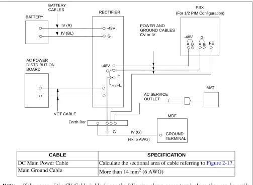
Figure 2-14 DC Main Power Cable and Main Ground Cable (1- or 2-PIM System) (Single IMG Configuration) . . . 27
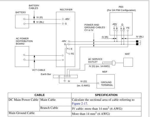
Figure 2-15 DC Main Power Cable and Main Ground Cable (3- or 4-PIM System) (Single IMG Configuration) . . . 28
Figure 2-16 DC Main Power Cable and Main Ground Cable (Multiple IMG Configuration) . . . 29
Figure 2-17 Calculation Method for Sectional Area. . . 32
Figure 2-18 Outline of Cables from Module Group to the Outside . . . 34
Figure 3-1 Scope of Installation Procedure . . . 35
Figure 3-2 Installation Procedure . . . 38
Figure 002-1 Locations of Base Unit Securing Holes . . . 43
Figure 002-2 Cable Hole on a Free-Access or Computer Floor . . . 44
Figure 002-3 Example of Special Stand . . . 46
Figure 002-4 Special Stand Installation Method . . . 46
Figure 002-5 Example of Elevation . . . 47
Figure 004-1 Mounting the Base Unit Directly onto the Floor . . . 51
Figure 004-2 Mounting the Base Unit on a Free-Access or Computer Floor . . . 52
Figure 004-3 Mounting the Base Unit on a Free-Access or Computer Floor via Elevation. . . 52
Figure 004-4 Setting the BASEU via Special Stand . . . 53
Figure 005-1 Procedure for Mounting Units and Modules. . . 54
Figure 005-2 Locations of FANU. . . 55
Figure 005-3 Mounting of FANU (on TOPU) . . . 56
Figure 005-4 Attachment of FAN Fuse (PZ-M369) . . . 57
Figure 005-5 Cable Connections for FANU on TOPU. . . 58
Figure 005-6 Connection of “FAN” Connector Cable (TOPU-PIM) . . . 59
Figure 005-7 Attachment of the Top Cover . . . 60
Figure 005-8 Relocation of FANU and Insertion into FAN BOX . . . 62
Figure 005-9 FAN Cable Connections for FC0/FC1/FC2 Connectors . . . 63
Figure Title Page
Figure 005-11 Connection of “FAN” Connector Cable (FAN BOX-PIM) . . . 66
Figure 005-12 Insertion of NFILU . . . 68
Figure 005-13 Attaching of NFILU. . . 68
Figure 005-14 Cabling Diagram of NFILU. . . 69
Figure 008-1 Detail of Cable Running . . . 73
Figure 008-2 Detail of Cable Running (Multiple IMG Configuration) . . . 74
Figure 008-3 Connection of Power and Ground Cables to Power Receiving Terminal . . . 75
Figure 008-4 Example Connection Diagram-DC-DC Converter for Message Waiting Lamps . . . 77
Figure 008-5 Removal of Shorting Piece and Cable Connection . . . 78
Figure 008-6 Placing the Clamp Terminal on the Die . . . 80
Figure 008-7 Clamping Method. . . 80
Figure 008-8 Stripped Length of Main and Branch Cable . . . 82
Figure 008-9 Inserting of Cables into Terminal . . . 83
Figure 008-10 Clamping for Branch Jointing . . . 83
Figure 008-11 Taping . . . 84
Figure 008-12 Covering. . . 84
Figure 009-1 Removal of Card Stopper . . . 87
Figure 009-2 Extraction of Circuit Cards . . . 90
Figure 009-3 Circuit Card Mounting (Partial Insertion) . . . 90
Figure 009-4 Removal of Front Panel and Top Cover from CPR . . . 91
Figure 009-5 Insertion of ISAGT and LANI Cards into CPR Slots . . . 92
Figure 009-6 Reattachment of CPR Top Cover and Front Panel . . . 93
Figure 009-7 Accommodation of New CPR into LPM . . . 94
Figure 009-8 Insertion of New HFD into CPR . . . 95
Figure 010-1 Locations of Connectors on the PIM Backplane . . . 103
Figure 010-2 Locations of Connectors on the LPM Backplane . . . 104
Figure 010-3 Location of Connectors on the TSWM Backplane (Multiple IMG Configuration) . . . 105
Figure 010-4 Locations of Connectors on the Power Distribution Terminal Board (PZ-M371) . . . 106
Figure 010-5 Power Cable Connections for 1-PIM System (Single IMG Configuration) . . . 107
Figure 010-6 Details on Power Cable Connections (for 1-PIM System) (Single IMG Configuration) . . 108
Figure 010-7 Power Cable Connections for 2-PIM System (Single IMG Configuration) . . . 110
Figure 010-8 Details on Power Cable Connections (for 2-PIM System) (Single IMG Configuration) . . 111
Figure 010-9 Power Cable Connections for 3-PIM System (Single IMG Configuration) . . . 113
Figure 010-10 Details on Power Cable Connections (for 3-PIM System) (Single IMG Configuration) . . 114
Figure 010-11 Power Cable Connections for 4-PIM System (Single IMG Configuration) . . . 116
Figure 010-12 Details on Power Cable Connections (for 4-PIM System) (Single IMG Configuration) . . 117
Figure 010-13 Power Cable Connection for IMG0 (Multiple IMG Configuration) . . . 119
Figure 010-14 Power Cable Connection for IMG1 (1-PIM System) (Multiple IMG Configuration) . . . 121
Figure 010-15 Power Cable Connection for IMG1 (2-PIM System) (Multiple IMG Configuration) . . . 123
Figure 010-16 Power Cable Connection for IMG1 (3-PIM System) (Multiple IMG Configuration) . . . 125
Figure 010-17 Power Cable Connection for IMG1 (4-PIM System) (Multiple IMG Configuration) . . . 127
Figure 010-18 Power Cable Connection for IMG2/3 (1-PIM System) (Multiple IMG Configuration) . . . . 129
Figure 010-19 Power Cable Connection for IMG2/3 (2-PIM System) (Multiple IMG Configuration) . . . . 131
Figure 010-20 Power Cable Connection for IMG2/3 (3-PIM System) (Multiple IMG Configuration) . . . . 133
Figure 010-21 Power Cable Connection for IMG2/3 (4-PIM System) (Multiple IMG Configuration) . . . . 135
Figure Title Page
Figure 010-25 Details on Bus Cable Connections (for 2-PIM System) (Single IMG Configuration) . . . . 141
Figure 010-26 Bus Cable Connections for 3-PIM System (Single IMG Configuration) . . . 143
Figure 010-27 Details on Bus Cable Connections (for 3-PIM System) (Single IMG Configuration) . . . . 144
Figure 010-28 Bus Cable Connections for 4-PIM System (Single IMG Configuration) . . . 146
Figure 010-29 Details on Bus Cable Connections (for 4-PIM System) (Single IMG Configuration) . . . . 147
Figure 010-30 Internal Bus Cable Connection for IMG0 (Multiple IMG Configuration) . . . 149
Figure 010-31 Internal Bus Cable Connection for IMG1 (1-PIM System) (Multiple IMG Configuration) . . . 151
Figure 010-32 Internal Bus Cable Connection for IMG1 (2-PIM System) (Multiple IMG Configuration) . . . 152
Figure 010-33 Internal Bus Cable Connection for IMG1 (3-PIM System) (Multiple IMG Configuration) . . . 154
Figure 010-34 Internal Bus Cable Connection for IMG1 (4-PIM System) (Multiple IMG Configuration) . . . 156
Figure 010-35 Internal Bus Cable Connection for IMG2/3 (2-PIM System) (Multiple IMG Configuration) . . . 158
Figure 010-36 Internal Bus Cable Connection for IMG2/3 (3-PIM System) (Multiple IMG Configuration) . . . 159
Figure 010-37 Internal Bus Cable Connection for IMG2/3 (4-PIM System) (Multiple IMG Configuration) . . . 160
Figure 011-1 Inter-Frame ISA Bus Cable Connection for IMG0-IMG1 . . . 162
Figure 011-2 Inter-Frame Bus Cable Connection for IMG0-IMG1 . . . 163
Figure 011-3 Inter-Frame Bus Cable Connection for IMG1-IMG2 (1-PIM System) . . . 165
Figure 011-4 Inter-Frame Bus Cable Connection for IMG1-IMG2 (2-PIM System) . . . 166
Figure 011-5 Inter-Frame Bus Cable Connection for IMG1-IMG2 (3-PIM System) . . . 168
Figure 011-6 Inter-Frame Bus Cable Connection for IMG1-IMG2 (4-PIM System) . . . 170
Figure 011-7 Inter-Frame Bus Cable Connection for IMG1-IMG3 (1-PIM System) . . . 172
Figure 011-8 Inter-Frame Bus Cable Connection for IMG1-IMG3 (2-PIM System) . . . 173
Figure 011-9 Inter-Frame Bus Cable Connection for IMG1-IMG3 (3-PIM System) . . . 175
Figure 011-10 Inter-Frame Bus Cable Connection for IMG1-IMG3 (4-PIM System) . . . 177
Figure 011-11 Inter-Frame Alarm Bus Cable Connection for IMG0-IMG1 . . . 179
Figure 011-12 Inter-Frame Alarm Bus Cable Connection for IMG0-IMG2 . . . 181
Figure 011-13 Inter-Frame Alarm Bus Cable Connection for IMG0-IMG3 . . . 183
Figure 012-1 Front Cable Connections between Circuit Cards for CCIS/ISDN . . . 185
Figure 013-1 LT Cable Routing . . . 189
Figure 013-2 Cable Routing of Circuit Card Front Cable . . . 190
Figure 013-3 Example of Cable Tying Using Tie-Wrap. . . 193
Figure 013-4 Cable Support Assembly . . . 195
Figure 013-5 Clamp Winding. . . 197
Figure 013-6 Termination of Installation Cables . . . 198
Figure 015-1 Cross Connection of Stations . . . 201
Figure 015-2 Cross Connection of Trunks (C.O. Lines and Tie Lines) . . . 203
Figure 015-3 Mounting Locations of PFT (PA-M53) . . . 204
Figure 015-4 Cross Connection for PFT . . . 206
Figure 015-5 Connection of Alarm Indicating Panel and Music on Hold (Single IMG Configuration) . . 208
Figure 015-6 Connection of Alarm Indicating Panel (Multiple IMG Configuration) (1/2) . . . 210
Figure 015-7 Connection of Music on Hold (Multiple IMG Configuration) . . . 211
Figure Title Page
Figure 015-9 Outer View of External Switch . . . 215
Figure 015-10 Connection of External Switches . . . 216
Figure 015-11 Connection of Announcement Machine . . . 218
Figure 015-12 Connection of Paging Equipment . . . 220
Figure 015-13 Outer View of Dterm Series E . . . 221
Figure 015-14 Cable Connection for Dterm Series E . . . 222
Figure 015-15 PLO Pin Assignments for Receiving Clock (Single IMG Configuration) . . . 224
Figure 015-16 PLO Pin Assignments for Receiving Clock (Multiple IMG Configuration) . . . 225
Figure 015-17 Cable Connection Diagram for Accepting Synchronization Clocks from an External High-Stability Oscillator (Single IMG Configuration). . . 226
Figure 015-18 Cable Connection Diagram for Accepting Synchronization Clocks from an External High-Stability Oscillator (Multiple IMG Configuration) . . . 227
Figure 015-19 Cable Connection Diagram for Distributing Clock from a Digital Interface (Single IMG Configuration) . . . 228
Figure 015-20 Cable Connection Diagram for Distributing Clock from a Digital Interface (Multiple IMG Configuration) . . . 229
Figure 016-1 Outer View of Desk Console . . . 230
Figure 016-2 Cable Connection Diagram for Desk Console (1 of 2) . . . 231
Figure 016-3 Cable Connection Diagram (When the Power Is Supplied from the PBX). . . 234
Figure 016-4 Cable Connection Diagram (When Using Local Power Supply) . . . 236
Figure 016-5 Cable Connection Diagram for DESK CONSOLE Modular Block . . . 237
Figure 016-6 Headset . . . 238
Figure 016-7 Mounting of Handset (Left Side of DESK CONSOLE). . . 239
Figure 016-8 Mounting of Handset (Right Side of DESK CONSOLE) . . . 242
Figure 016-9 RECC Card Cable Connection Diagram . . . 245
Figure 016-10 Three DESK CONSOLEs and One Recording Equipment . . . 246
Figure 016-11 Six DESK CONSOLEs and One Recording Equipment . . . 247
Figure 016-12 8-core Line Cable. . . 248
Figure 016-13 Connection of AC-DC Adapter. . . 249
Figure 016-14 Add-On Console Cable Connection Diagram (When the Power Is Supplied from the PBX) . . . 250
Figure 016-15 Add-On Console Cable Connection Diagram (When Using Local Power Supply) . . . 251
Figure 016-16 Cable Connection Diagram for Add-On Console Modular Block . . . 252
Figure 016-17 Mounting of Add-On Console (Right Side of DESK CONSOLE) . . . 253
Figure 016-18 Mounting of Add-On Console (Left Side of DESK CONSOLE) . . . 255
Figure 016-19 Connection of AC-DC Adapter for Add-On Console . . . 257
Figure 016-20 Displaying the Configuration Menu . . . 259
Figure 016-21 Selecting a Configuration Item. . . 261
Figure 016-22 Assigning Configuration Data . . . 262
Figure 016-23 Updating Configuration Data . . . 271
Figure 017-1 Cabling of MAT when Using Ethernet . . . 273
Figure 017-2 Cable Connection Diagram for the MAT . . . 274
Figure 017-3 Cabling of MAT Using Modems . . . 276
Figure 017-4 Connection of System Message Printer. . . 277
Figure 017-5 Detail of RS-232C CA-(0) . . . 278
Figure Title Page
Figure 018-2 Cable Connection Diagram for the SMDR Equipment. . . 282
Figure 018-3 Connection of SMDR by Using MODEM . . . 283
Figure 022-1 LED Indications in Normal Operation (Single IMG Configuration) . . . 300
Figure 022-2 LED Indications of IMG0 in Normal Operation (Multiple IMG Configuration). . . 301
Figure 022-3 LED Indications of IMG1 in Normal Operation (Multiple IMG Configuration). . . 302
Figure 022-4 LED Indications of IMG 2/3 in Normal Operation (example) (Multiple IMG Configuration) . . . 303
Figure 023-1 Alarm Lamps on the TOPU . . . 304
Figure 5-1 Example of Entry to Test Check Column . . . 308
Figure 026-1 How to Perform a Control System Changeover (Single IMG Configuration) . . . 314
Figure 026-2 How to Perform a Control System Changeover (Multiple IMG Configuration). . . 314
Figure 026-3 LEDs and Switches on TSW/MUX. . . 315
Figure 026-4 LEDs and Switches for System Changeover (Multiple IMG Configuration) . . . 317
Figure 026-5 System Block Diagram (TSW and MUX) (Multiple IMG Configuration) . . . 318
Figure 026-6 System Block Diagram (GT and Other Controlling Blocks) (Multiple IMG Configuration) . . . 319
Figure 026-7 System Block Diagram (Speech Path) (Multiple IMG Configuration). . . 320
Figure 027-1 System Initialization via ‘Start’ Button . . . 321
Figure 032-1 COT Test Configuration . . . 330
Figure 032-2 TLT Test Configuration . . . 330
Figure 032-3 DTI Test Configuration . . . 331
Figure 047-1 Combination of Tie Line Network and Public Network . . . 352
Figure 047-2 Tie Line Network . . . 352
Figure 048-1 Test of Tandem Connection to Tie Line. . . 353
Figure 049-1 Example of PAD Setting . . . 355
Figure 049-2 Example of PAD Setting for CCIS . . . 356
Figure 7-1 Mounting of the Covers in a Full System . . . 366
Figure 7-2 Mounting of the Covers . . . 367
Figure 7-3 Side Cover Mounting Method (BASEU+LPR+PIM0) . . . 368
Figure 7-4 Side Cover Mounting Method (PIM). . . 369
Figure 7-5 Rear Cover Mounting Method (BASEU+LPR+PIM0). . . 370
Figure 7-6 Rear Cover Mounting Method (PIM) . . . 371
Figure 7-7 Rear Cover Mounting Method (FANU). . . 372
Figure 7-8 Front Cover Mounting Method in a Full System. . . 373
Figure 7-9 Front Cover Mounting Method (BASEU+LPR+PIM0) . . . 374
Figure 7-10 Front Cover Mounting Method (PIM) . . . 375
Figure 7-11 Front Cover Mounting Method (FANU) . . . 376
Figure 7-12 Locations of Inter-frame Brackets . . . 377
Table Title Page
Table 2-1 Temperature and Humidity . . . 8
Table 2-2 Typical Installation Tools . . . 13
Table 2-3 Conditions for Configuration . . . 15
Table 2-4 Controlling Circuit Cards in LPM . . . 22
Table 2-5 Controlling Circuit Cards in PIM 0 (Single IMG Configuration Only) . . . 23
Table 2-6 Controlling Circuit Cards in PIM. . . 24
Table 2-7 Controlling Circuit Cards in TSWM (Multiple IMG Configuration) . . . 25
Table 2-8 Clamp Terminal Shape and Purpose . . . 30
Table 2-9 Selection of T-type Clamp Terminal. . . 31
Table 2-10 Clamping Tool . . . 32
Table 2-11 Calculation of Number of Cables . . . 33
Table 002-1 Specification of Anchor Bolts-Sleeve Expansion Type . . . 41
Table 008-1 Stripped Length . . . 82
Table 010-1 Quick Reference Table (1/6) . . . 97
Table 010-2 Power Cable Connection for IMG0 (Single IMG Configuration). . . 109
Table 010-3 Power Cable Connections for 2-PIM System (Single IMG Configuration) . . . 112
Table 010-4 Power Cable Connections for 3-PIM System (Single IMG Configuration) . . . 115
Table 010-5 Power Cable Connections for 4-PIM System (Single IMG Configuration) . . . 118
Table 010-6 Power Cable Connection for IMG0 (Multiple IMG Configuration) . . . 120
Table 010-7 Power Cable Connection for IMG1 (1-PIM System) (Multiple IMG Configuration) . . . 122
Table 010-8 Power Cable Connection for IMG1 (2-PIM System) (Multiple IMG Configuration) . . . 124
Table 010-9 Power Cable Connection for IMG1 (3-PIM System) (Multiple IMG Configuration) . . . 126
Table 010-10 Power Cable Connection for IMG1 (4-PIM System) (Multiple IMG Configuration) . . . 128
Table 010-11 Power Cable Connection for IMG2/3 (1-PIM System) (Multiple IMG Configuration) . . . . 130
Table 010-12 Power Cable Connection for IMG2/3 (2-PIM System) (Multiple IMG Configuration) . . . . 132
Table 010-13 Power Cable Connection for IMG2/3 (3-PIM System) (Multiple IMG Configuration) . . . . 134
Table 010-14 Power Cable Connection for IMG2/3 (4-PIM System) (Multiple IMG Configuration) . . . . 136
Table 010-15 Bus Cable Connections for 1-PIM System (Single IMG Configuration) . . . 139
Table 010-16 Bus Cable Connections for 2-PIM System (Single IMG Configuration) . . . 142
Table 010-17 Bus Cable Connections for 3-PIM System (Single IMG Configuration) . . . 145
Table 010-18 Bus Cable Connections for 4-PIM System (Single IMG Configuration) . . . 148
Table 010-19 Internal Bus Cable Connection for IMG0 (Multiple IMG Configuration) . . . 150
Table 010-20 Internal Bus Cable Connection for IMG1 (1-PIM System) (Multiple IMG Configuration) . 151 Table 010-21 Internal Bus Cable Connection for IMG1 (2-PIM System) (Multiple IMG Configuration) . 153 Table 010-22 Internal Bus Cable Connection for IMG1 (3-PIM System) (Multiple IMG Configuration) . 155 Table 010-23 Internal Bus Cable Connection for IMG1 (4-PIM System) (Multiple IMG Configuration) . 157 Table 011-1 Inter-Frame ISA Bus Cable Connection for IMG0-IMG1 . . . 162
Table 011-2 Inter-Frame Bus Cable Connection for IMG0-IMG1 . . . 164
Table 011-3 Inter-Frame Bus Cable Connection for IMG1-IMG2 (1-PIM System) . . . 165
Table 011-4 Inter-Frame Bus Cable Connection for IMG1-IMG2 (2-PIM System) . . . 167
Table 011-5 Inter-Frame Bus Cable Connection for IMG1-IMG2 (3-PIM System) . . . 169
Table 011-6 Inter-Frame Bus Cable Connection for IMG1-IMG2 (4-PIM System) . . . 171
Table 011-7 Inter-Frame Bus Cable Connection for IMG1-IMG3 (1-PIM System) . . . 172
Table 011-8 Inter-Frame Bus Cable Connection for IMG1-IMG3 (2-PIM System) . . . 174
Table 011-9 Inter-Frame Bus Cable Connection for IMG1-IMG3 (3-PIM System) . . . 176
Table 011-10 Inter-Frame Bus Cable Connection for IMG1-IMG3 (4-PIM System) . . . 178
Table 011-11 Inter-Frame Alarm Bus Cable Connection for IMG0-IMG1 . . . 180
Table Title Page
IMPORTANT — SAVE THESE INSTRUCTIONS
(1) Never install telephone wiring during a lightning storm.
(2) Never install telephone jacks in wet locations unless the jack is specifically designed for wet locations.
(3) Never touch uninsulated telephone wires or terminals unless the telephone line has been disconnected at the network interface.
(4) Use caution when installing or moving telephone lines.
When using your telephone equipment, always follow basic safety precautions, such as the ones below, to reduce the risk of fire, electric shock, and injury:
(5) Read and understand all instructions.
(6) Follow all warnings and instructions marked on the product.
(7) Disconnect this product from the power source before cleaning. Do not use liquid cleaners or aerosol cleaners. Use a damp cloth for cleaning.
(8) Do not use this product near water; for example, under water pipes near a bath tub, sink, or laundry tub, in a wet basement, or near a swimming pool.
(9) Do not place this product on an unstable cart, stand, or table. The product may fall, causing serious damage to the product.
(10) Slots and openings in the cabinet and the back or bottom are provided for ventilation, to protect it from overheating. These openings must not be blocked or covered. The openings should never be blocked by placing the product on a rug, or other similar surface. This product should never be placed near or over a radiator or heat register. This product should not be placed in a built-in installation unless proper ventilation is provided.
(11) This product should be operated only from the type of power source indicated on the marking label. If you are not sure of the type of power source available, consult with your local power company.
(12) Do not overload wall outlets and extension cords as this can result in the risk of fire or electric shock.
you to dangerous voltages or other risks. Incorrect reassembly can cause electric shock when the appliance is subsequently used.
(15) Unplug this product from the wall outlet and refer servicing to qualified service personnel under the following conditions:
(a) When the power supply cord or plug is damaged or frayed.
(b) If liquid has been spilled into the product.
(c) If the product has been exposed to rain or water.
(d) If the product does not operate normally by following the operating instructions. Adjust only those controls, that are covered by the operating instructions because improper adjustment of other controls may result in damage and will often require extensive work by a qualified technician to restore the product to normal operation.
(e) If the product has been dropped or the cabinet has been damaged.
(f) If the product exhibits a distinct change in performance.
(16) Avoid using a telephone (other than a cordless type) during an electrical storm. There may be a remote risk of electric shock from lightning.
1. REGULATORY REQUIREMENTS
The Federal Communications Commission (FCC) has established rules that permit the NEAX2400 IPX to be directly connected to the telephone network. A jack is provided on party lines or coin lines.
The telephone company may make changes in its technical operations and procedures. If such changes affect the compatibility or use of the NEAX2400 IPX, the telephone company is required to give adequate notice of the changes.
This equipment complies with the requirements in Part 15 of FCC Rules for a Class A computing device. Operation of this equipment in a residential area may cause unacceptable interference to radio and TV reception requiring the operator to take whatever steps are necessary to correct this interference.
2. FCC PART 15 REQUIREMENTS
In compliance with FCC Part 15 Rules, the following statement is provided:
3. FCC PART 68 REGISTRATION
3.1 Company Notification
Before installing the NEAX2400 IPX to the telephone network, the telephone company must be provided with the following:
• Your telephone number
• The FCC registration numbers:
JAPAN USA
• PBX: AY5JPN-74906-PF-E AY5USA-74905-PF-E
• Hybrid: AY5JPN-74904-MF-E AY5USA-74913-MF-E
The Ringer Equivalence Number is 2.1B; the required USOC jacks are RJ21X, RJ2EX, and RJ2GX.
WARNING
In the event of equipment malfunction, all repairs will be performed by NEC or an authorized distributor of NEC. It is the responsibility of users requiring service to report the need for service to NEC or to one of their authorized distributors.
If the equipment causes harm to the telephone network, the telephone company will notify you in advance that temporary discontinuance of service may be required. If advance notice is not practical, the telephone company will notify the customer as soon as possible. Also, you will be advised of your right to file a complaint with the FCC if you believe it is necessary.
The telephone company may make changes in its facilities, equipment, operations, or procedures that affect the operation of the equipment. If this happens, the telephone company will provide advance notice in order for you to make necessary modifications in order to maintain uninterrupted service.
If trouble is experienced with this equipment, please contact NEC America, Inc.’s Oregon plant at (503) 648-5000 for repair and/or warranty information. If the trouble is causing harm to the telephone network, the telephone company may request that you remove the equipment from the network until the problem is resolved.
NO REPAIRS CAN BE DONE BY THE CUSTOMER.
3.3 Location of FCC Compliance Labels
Labels stating the NEAX2400 IPX FCC registration number and compliance with FCC Parts 15 and 68 are attached to the Base Unit. If the unit is in a table-top configuration, the labels are located on the side of the enclosure. The appearance of the labels is as shown below:
4. DIRECT-INWARD DIALING (DID) CALLS
Allowing this equipment to be operated in such a manner as to not provide for proper answer supervision is a violation of Part 68 of the FCC’s rules.
PROPER ANSWER SUPERVISION IS WHEN:
(a) This equipment returns answer supervision to the PSTN when DID calls are:
• Answered by the called station
• Answered by the attendant
NEAX2400 IMS-IP
Complies With Part 68 FCC Rules
FCC Registration Numbers:AY5USA-74905-PF-E AY5USA-74913-MF-E
Ringer Equivalence: 2.1B
(b) This equipment returns answer supervision on all DID calls forwarded to the PSTN. Permissible exceptions are:
• A call is unanswered
• A busy tone is received
• A reorder tone is received.
EQUAL ACCESS REQUIREMENTS
This equipment is capable of providing users access to interstate providers of operator services through the use of access codes. Modification of this equipment by call aggregators to block access dialing codes is a violation of the Telephone Operator Consumers Act of 1990.
5. REGULATORY INFORMATION ON SINGLE-LINE ANALOG TELEPHONES
NEC single-line telephones comply with Part 68 of FCC Rules. On the bottom of the equipment is a label that states, among other information, the FCC registration number and ringer equivalence number (REN) for the equipment. If requested, this information should be provided to the telephone company.
The equipment uses the following USOC jacks: RJ11C.
The equipment should be used only behind a PBX or KTS. The REN is used to determine the quantity of devices that may be connected to the telephone line. Excessive RENs on the telephone line may result in the devices not ringing in response to an incoming call. In most, but not all, areas, the sum of RENs should not exceed five (5.0). To be certain of the number of devices that may be connected to the line as determined by the total RENs, contact the telephone company to determine the maximum REN for the calling area.
6. HEARING AID COMPATIBILITY
The Dterm terminals provided for the NEAX2400 IPX are hearing aid compatible. FCC rules prohibit the use of
non-hearing aid compatible telephones.
NEC-type single-line telephone sets used in conjunction with the NEAX2400 IPX are hearing aid compatible. If other than NEC-type single-line telephone sets are to be used with this system, ensure that these are hearing aid compatible.
CAUTION:The act of monitoring or recording telephone conversations under certain circumstances may
violate federal or state statutes. Consultation with your legal counsel prior to engaging in such practices would be advisable.
7. INDUSTRY CANADA CS-03
Certification number: 140 5452A
Ringer Equivalence Number: 2.1
connection. In some cases, the company’s inside wiring associated with a single line individual service may be extended by means of a certified connector assembly (telephone extension cord). The customer should be aware that compliance with the above conditions may not prevent degradation of service in some situations.
Repairs to certified equipment should be made by an authorized Canadian maintenance facility designated by the supplier. Any repairs or installations made by the user to this equipment, or equipment malfunctions, may give the telecommunications company cause to request that the user disconnect the equipment.
Users should ensure for their own protection that the electrical ground connections of the power utility, telephone lines, and internal metallic water pipe system, if present, are connected together. This protection may be particularly important in rural areas.
CAUTION:Users should not attempt to make such connections themselves, but should contact the
appropriate electric inspection authority, or electrician, as appropriate.
NOTICE: The “Ringer Equivalence Number” assigned to each terminal device provides an indication of the maximum number of terminals allowed to be connected to a telephone interface. The termination on an interface may consist of any combination of devices subject only to the requirement that the sum of the Ringer Equiva-lence Numbers of all the devices does not exceed 5.
8. SAFETY LISTING/CERTIFICATIONS
This equipment has been listed by Underwriters Laboratories and found to comply with all the applicable requirements of the standard for telephone equipment U.L. 1459. This equipment complies with Canadian Standards Association standard C 22.2 No. 225.
8.1 Safety Considerations
When using your telephone equipment, basic safety precautions should always be followed to reduce the risk of fire, electric shock and injury, including the following:
1. Never install telephone wiring during a lightning storm.
2. Never install telephone jacks in wet locations unless the jack is specifically designed for wet locations.
3. Never touch uninsulated telephone wires or terminals unless the telephone line has been disconnected at
the network interface.
4. Use caution when installing or modifying telephone lines.
1. GENERAL
During the period from equipment carry-in of the NEAX2400 IPX until it is placed in service, installers must complete the following:
• Installation of the system and its peripheral equipment
• System startup
• Installation test
• Miscellaneous jobs
This manual explains how to proceed with these activities and related precautions. Before engaging in any phase
of the installation, please read Section 2., “HOW TO FOLLOW THE MANUAL”.
2. HOW TO FOLLOW THE MANUAL
2.1 Outline
The following chapters outline in order the work the installer will perform:
• Chapter 2, “INSTALLATION DESIGN”
This chapter explains installation design and preparation of the required installation materials.
• Chapter 3, “INSTALLATION PROCEDURE”
This chapter explains the procedures pertaining to equipment carry-in, installation, power supply (cabling, wiring), etc., of the system and also explains the installation procedures concerning peripheral equipment (MDF, Rectifier, Terminal Equipment.).
• Chapter 4, “SYSTEM STARTUP”
This chapter explains the procedures for initial power-on and office data entry upon completion of the system installation.
• Chapter 5, “INSTALLATION TEST PROCEDURE”
This chapter explains the test procedures the installer will perform, upon completion of the system startup, to determine:
• If the system operates as directed by the office data.
• Whether reinitialization or system changeover can be performed.
• Whether the interface with the associated distant office is normal.
• Chapter 6, “FAULT RECOVERY DURING TESTS”
This chapter explains the recovery procedure that the installer needs to follow in case a fault occurs pertaining to system startup and basic connections.
• Chapter 7, “WORK AFTER INSTALLATION TESTS”
2.2 How to Follow NAPs
This manual categorizes the work contents of installation, system startup, and installation tests into detailed work items, and each work item is assigned an NEC Action Procedure (NAP) number.
The following shows how to interpret a NAP number.
Figure 1-1 shows an example of an NAP. NAP- XXX-XXX
Serial Number (000-999) Note
Work Category Number
200: Installation
215: System Startup, Installation Test, Fault Recovery
Figure 1-1 Example of NAP
NAP- 200-004 Sheet 3/3
Installation of the Base Unit
1. INSTALLING THE BASE UNIT USING A SPECIAL STAND
START
Securing the Base Unit Secure the Base Unit onto the special stand as shown in
Figure 004-4.
Level Check Check the level of the Base Unit. If necessary, adjust the
level by inserting spacers beneath the Base Unit.
END
BASE U
SPECIAL STAND
BOLT (M-10) LOCK WASHER PLAIN WASHER
NAP Number
2.3 How To Follow Trees
This manual explains how to perform a predetermined procedure (work contents covered in each NAP) in a
“Tree” format as shown in Figure 1-2. Before engaging in the intended work, be sure to understand the work
contents by tracing the given tree.
Figure 1-2 Example of a Tree
START
On the MDF, make temporary cross connections between the Trunk for Direct-In Termination (DIT) and an LC.
C.O. Line Incoming Call Station “B” dials the number of LC “C” (Station “C”).
Incoming Call to Station via
DIT Trunk The call terminates to Station “A”; Station “A” rings.
Confirm that the ringing is distinct from that of an intra-office call or ordinary C.O. call.
• The ringing signal for Direct-In Termination calls can
be the same as that used for C.O. calls if the related Office Data is assigned.
System Data SYS1, INDEX 72, SYS3, INDEX 0, and parameter DR of Command “ARTD”.
Answer and Talk Station “A” goes off-hook.
Station “A” and “B” talk with each other.
Release Station “A” and “B” both go on-hook.
Remove the temporary cross connections.
Figure 1-3 Static Caution Indication
This manual provides “Static Caution” indicators (see Figure 1-3) where necessary to indicate that installers will
be working with static-sensitive components.
The 3M Model 8012 Portable Field Service Kit, shown in Figure 1-4, is an effective countermeasure against
static electricity.
Figure 1-4 3M Model 8012 Portable Field Service Kit
Note: 3M is a registered trademark of Minnesota Mining and Manufacturing, Inc.
ATTENTION
Contents Static Sensitive Handling
Precautions Required
Wrist Strap
2.4 Figure and Table Numbers
Each Figure and Table within this manual follows the numbering pattern shown below.
1. Figure and table in NAP
Figure XXX-X
Serial number of Figures in each NAP
Serial number (000-999) of the NAP in which the Figure exists
2. Other figure and table
Table X-X
Serial number of Table in each Chapter
Number of the Chapter in which the Table exists
Remember this numbering pattern to find the desired Figure or Table.
2.5 Essential/Critical Information
To prevent accidents or equipment damage from occurring during installing, each manual provides WARNING,
CAUTION, and Note: indicators to draw the installer’s attention to specific matters.
1. Meaning
WARNING: Personal injury may result.
CAUTION: Damage to the equipment and/or the system may result.
Note: Indicates an item which requires special attention.
2. Locations of Indicators
WARNING and CAUTION indicators are at the top of the page. Notes are part of the work procedures on
1. GENERAL
This chapter provides the following information on installation design and preparation of the required installation materials:
• Environmental Requirements
• Floor Space
• Floor Load Requirements
• Equipment Room Requirements
• Power Supply Requirements
• MDF Requirements
• Installation Tools
• System Accommodation
• Installation Cables
2. ENVIRONMENTAL REQUIREMENTS
The PBX is sensitive to the same rises in temperature and humidity as a computer. Depending on the installation environment, the PBX may require air conditioning. The following paragraphs address these environmental conditions.
• Temperature and Humidity
• Heat Generation from Switching Equipment
2.1 Temperature And Humidity
Table 2-1 shows the environmental conditions required in the switching equipment room.
If the switching system operates in an environment that does not meet these specifications, the reliability of the switching equipment may be impaired. Improper operating conditions can cause circuit boards, etc., to deteriorate. Without equipment to remove the heat generated by the system, or if the temperature or humidity fluctuates repeatedly, the system’s electronic parts can be adversely affected. Such conditions will promote corrosion of metal parts and deterioration of insulation, thereby lowering the overall reliability of the system. Therefore, to enable the equipment to operate for the extent of its expected lifetime, carefully consider the location of the equipment, proper ventilation, and air conditioning.
Note: A short period means a period not exceeding three consecutive days (72 hours) or 15 days (360 hours) in a year.
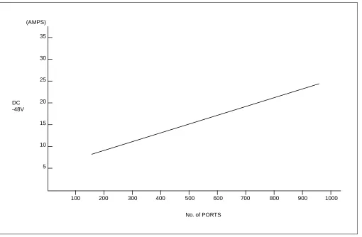
2.2 Heat Generation From Switching Equipment
Figure 2-1 shows heat generation from the switching equipment with respect to current consumption.
Table 2-1 Temperature and Humidity
TEMPERATURE RELATIVE
HUMIDITY REMARKS
During Operations
Normal Operations 5°C - 30°C (41°F -86°F) 15% - 65%
Short Period Note 0°C - 40°C (32°F-104°F) 15% - 90%
During Storage & In Transit –18°C - 50°C (0°F -122°F) 8% - 90%
Temperature Change Maximum 5°C/30 Min. (9°F/30 Min.) 90%
Note: BTU; British Thermal Unit (1 BTU=1058.4J)
BTU/HT
100 200 300 400 500 600 700 800 900 1000
No. of PORTS (2.1 m)
(1.8 m)
(1.5 m)
(1.2 m)
(.9 m)
3. FLOOR SPACE
1. The PBX requires floor space for the following system equipment:
• Switching Equipment (Module Group)
• Maintenance Administration Terminal (MAT)
• MDF
• Rectifier
• Batteries
• Attendant Console
2. The required floor space for the various equipment rooms is as follows.
• Switching Equipment Room: For installing the Module Group, MAT, MDF, and Rectifier
• Battery Room: For installing Batteries
• Operator Room: For installing an Attendant Console with desk and chair
3. Equipment Room: free access floor or computer floor
4. FLOOR LOAD REQUIREMENTS
Required floor capacities are as follows:
• Switching Equipment Room: More than 3430 Pa (71.6 pounds per square foot)
• Operator Room: More than 2940 Pa (61.4 pounds per square foot)
5. EQUIPMENT ROOM REQUIREMENTS
Make sure that the floor of each room meets the specified conditions:
5.1 Floor Surface
1. Switching Equipment Room
• The maximum difference in floor level at each point within the room should be less than +5 mm (0.2
inch).
• The floor should be an elevated-type floor such as a free access floor or computer room floor.
2. Battery Room
• The floor should have a slope (1/1000) and drain at the end of the slope.
5.2 Wall
Switching Equipment Room
• Unless a free access floor is used, a concrete wall is necessary for installation of the cable racks.
• The walls should be painted so that the wall materials do not generate dust, etc.
• The maximum difference in level at the wall surface should be less than +5 mm (0.2 inch).
5.3 Ceiling
Switching Equipment Room
• The ceiling height should be more than 2.3 meters (7.5 feet).
5.4 Lighting Facilities
1. Switching Equipment Room
• Fluorescent lamps are recommended.
• At least 200 lux at the floor level is necessary.
2. Operator Room
• Fluorescent lamps are recommended.
• At least 200 lux at the floor level is necessary.
3. Battery Room
• Anti-explosion lamps must be used.
• At least 150 lux at the floor level is necessary.
6. POWER SUPPLY REQUIREMENTS
6.1 Main Source Power
The PBX requires an operating power of -48 V DC ±5 V DC. This DC operating power is supplied from the rectifier that receives AC power from the commercial AC power source. For greater system reliability, the PBX should have a backup supply of DC operating power for a predetermined duration from the batteries installed as the auxiliary power supply source.
Note 1: When the rectifier is in the equalize state (charging the batteries), the output DC voltage should be 1.5 to 2 V higher than the float voltage. Please refer to the voltages for floating and equalizing below:
Float: 50.5 V DC
Equalize: 52 V DC(Refer to Note 2.)
Note 2: With an EMF panel (Diode Drop), the equalize voltage is 1.5 to 2 V higher. Without an EMF panel, the float
and equalize voltage are the same (50.5 V).
Note 3: The main source power is AC input.
Note 4: Noise present in the -48 V output from the rectifier should be less than 5 mV.
6.2 Current Consumption
The PBX operates on -48 V ±5 V DC, which is supplied from external power equipment (the rectifier and the battery).
The DC converter in each module provides the various DC voltages required within the system. The DC-DC converter, upon receiving the -48 V DC-DC source power, converts it into various DC-DC voltages and supplies them to the associated circuits.
Figure 2-2 shows the current consumption of the PBX.
Figure 2-2 Current Consumption of the PBX
(AMPS) 35
30
25
20
15
10
5
100 200 300 400 500 600 700 800 900 1000
No. of PORTS DC
6.3 Power Distribution Box Requirements
Consider the following when installing the Power Distribution Box (PDB):
1. The AC power source service outlet and the fuse for the junction box should be provided independently of
any equipment other than the switching equipment.
2. A warning notice should be attached to be PDB circuit breaker so that it will not be turned off accidentally.
3. The Power Distribution Box should be installed at a location that is easy to reach.
4. The Power Distribution Box should be installed at a location where the connecting cables extending to the
switching equipment will not be broken accidentally.
5. The PDB cables should be run in such a way that they do not hamper the technician performing the
installation.
6. The Personal Computer (MAT) must have a separate AC service outlet.
6.4 Grounding
System grounding must have a specific ground resistance and AC noise level and should be connected to a predetermined terminal in the PBX.
Please refer to the standard grounding requirements shown below.
• Communication grounding: Less than 1 ohm
• Security ground for Module Group: Less than 1 ohm
• Grounding for the line protector of the MDF: Less than .1 ohm
Note: The AC ripple of various types of grounding should be less than 1/2 V-pp.
7. MDF REQUIREMENTS
Either a self-standing or wall-mounted type MDF can be used. The MDF must be equipped with the following terminal blocks:
• Arrester board for C.O. lines and external lines
• Test spring terminals for localization tests
• Local Block terminals
8. INSTALLATION TOOLS
Table 2-2 shows the tools used in a typical NEAX2400 IPX installation.
Table 2-2 Typical Installation Tools
FUNCTION TOOLS PURPOSE
Marking • Steel Tape Measure
• L-Square
• Iron Square
• Iron Level
• Center Punch
• Step Ladder
• Scriber
For Leveling and Marking Plumb Line
Drilling • Electric Drill
• Electric Vibration Drill
• Hammer
• Point Drill
• Drill Bit for Concrete
• Concrete Chisel
• Drill Bit for Metal
• Power Cable Drum
• Extension Cable
Drilling
Module Group and Rack Installation
• Plump Bob
• Jigsaw
• Hacksaw Frame
• Hacksaw Blade
• Flat File
• Half Round File
• Set File
• Adjustable Angle Wrench
• Frame Cart
• Cutter
• Set Wrench
• Socket Wrench Set
• Step Ladder
• Phillips Screwdriver
• Screwdriver
• Plastic Hammer
Module Group and Rack Installation
Power Cable Installation
• Clamping Tool
(for End Terminal, Branch Terminal)
• Phillips Screwdriver
• Screwdriver
• Cutter
Power Cable Installation
See Note.
Miscellaneous • Circuit Tester
• Pocket Measure
• Scissors
• Wire Clipper
• Cable Cutter
• Nipper
• Wire Stripper
• Round Nose Pliers
• Non-Metallic Stick
• Solder-Helper
• Solder Sucker
• IC Clip
• Mini Test Probe
• Telephone Set
• Working Lamp
• Wrapping Tool
• Unwrapping Tool
• Soldering Iron
• Soldering Iron Stand
• Connector Clamping Tool
• Logic Checker and Counter
• Pen Light
• Precision Screwdriver (+)(-)
• IC Buzzer
• Tweezer
9. SYSTEM ACCOMMODATION
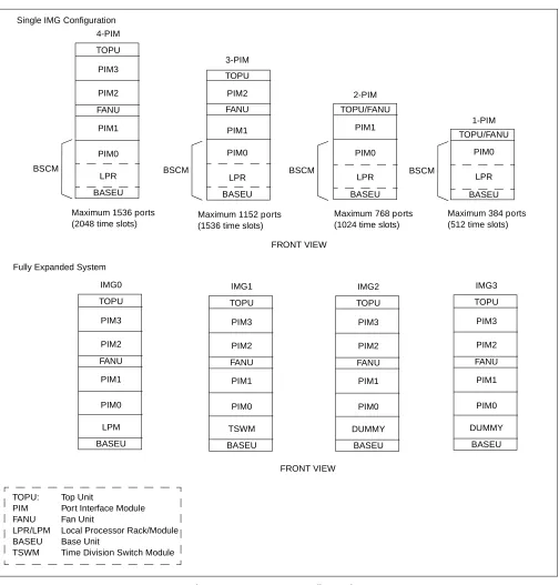
9.1 Port Interface Module Configuration and Conditions for Configuration
Figure 2-3 shows the Port Interface Module (PIM) configuration of the PBX, and Table 2-3 shows the conditions for configuration. TOPU PIM2 PIM3 PIM1 PIM0 TSWM FANU IMG1 BASEU
Maximum 1536 ports Maximum 1152 ports Maximum 768 ports Maximum 384 ports (2048 time slots) (1536 time slots) (1024 time slots) (512 time slots)
TOPU PIM2 PIM3 PIM1 PIM0 LPR FANU 4-PIM 3-PIM 2-PIM 1-PIM FANU TOPU TOPU/FANU TOPU/FANU BASEU
BASEU BASEU BASEU
LPR LPR LPR
PIM0 PIM0 PIM0
PIM1 PIM1
PIM2
BSCM BSCM BSCM BSCM
FRONT VIEW TOPU PIM2 PIM3 PIM1 PIM0 LPM FANU IMG0 BASEU FRONT VIEW TOPU PIM2 PIM3 PIM1 PIM0 DUMMY FANU IMG2 BASEU TOPU PIM2 PIM3 PIM1 PIM0 DUMMY FANU IMG3 BASEU Fully Expanded System
TOPU: Top Unit
PIM Port Interface Module FANU Fan Unit
LPR/LPM Local Processor Rack/Module BASEU Base Unit
Note: A NFILU is mounted in BASEU.
Table 2-3 Conditions for Configuration
UNIT NAME NUMBER OF PIMs CONDITIONS REMARKS
FANU (Fan Unit)
PIM
Less than two PIMs
Mounted in TOPU
PIM
Three or more PIMs
Mounted in between the 2nd PIM and the 3rd PIM
2nd NFILU (Noise Filter)
Less than two PIMs Not required
Three or more PIMs Mounted in BASEU
TOPU (Top Unit)
Figure 2-4 Time Slot, Group Number Assignment
Note 1: Extended Group No. can be used by FCH (PA-FCHA) card. For more detailed information, see
the “Fusion Network System Manual.”
Note 2: A PIM consists of 384 physical ports (512 total ports).
00 02 04 05 06 07 08 09 10 11 12 13 14 1516 17 18 19 20 21 22 23
PIM 192 TS 16 32 TS/Physical ports 16 16 16 16 16 16
16 163232
16 32 16 16 16 16 16 16
16 163232 192 TS Slot No. Number of Time Slots (16) PW R (16) PWR
00 02 04 05 06 07 08 09 10 11 12 13 14 1516 17 18 19 20 21 22 23
PIM 00
26
02 04 06 08 10 Slot No. (25) (24) 27 28 29 30 31 00 03
01 05 07 09 11
12 16 20 21 02 04 06 08 1013 17
14 15 19 23
18 22 01 03 05 07 1115 19
20 23 14 18 22 13 17 21 12 16 Group No.
Extended Group No.
Time Slots are allocated for a PIM as shown below:
09 26 27 28 29 30 31 TS/SW ports 48 TS/SW 48 TS/SW
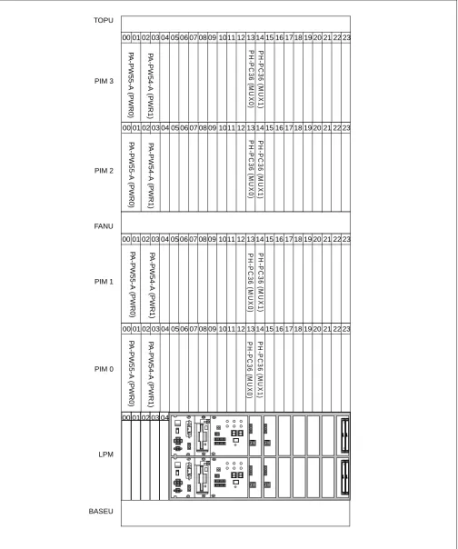
Figure 2-5 Face Layout (Single IMG Configuration) P H -S W1 0 (T SW 0) PH-S W 10 (T S W 1 ) PH-P C36 (MUX 0 ) PH -PC36 (M UX1) PH -PC36 (M UX0) P H -P C36 (M UX 0) P H -P C36 ( M UX 1) P H -P C36 (M UX 1)
0001 02 03 040506 07 08 09 1011121314151617181920212223
0001 02 03 040506 07 08 09 1011121314151617181920212223
0001 02 03 040506 07 08 09 1011121314151617181920212223
0001 02 03 040506 07 08 09 1011121314151617181920212223 TOPU PIM 3 PIM 2 FANU PIM 1 PIM 0 LPM BASEU P A -PW 54-A (PW R 1) P A -P W 55-A (P W R 0) P A -P W 54-A (P W R 1) P A -P W 55-A (PW R 0 ) P A -P W 54-A (P W R 1) P A -P W5 5-A (PW R 0) P A -PW 54-A (PW R 1) P A -P W 55-A (P W R 0)
00 01 02 03 04
P H -P C 3 6 (M U X 0 ) P H -P C 3 6 (M U X 1 ) P H -P C 36 ( M U X 0) P H -P C3 6 ( M UX 1 ) P H -P C 36 ( M U X 0) P H -P C3 6 ( M UX 0 ) PH -P C3 6 ( M UX1 ) P H -P C 36 ( M U X 1)
0001 02 03 040506 07 08 09 1011121314151617181920212223
0001 02 03 040506 07 08 09 1011121314151617181920212223
0001 02 03 040506 07 08 09 1011121314151617181920212223
0001 02 03 040506 07 08 09 1011121314151617181920212223 TOPU PIM 3 PIM 2 FANU PIM 1 PIM 0 LPM BASEU
00 01 02 03 04
Figure 2-7 Location of Terminating Resistors on the TSWM Back Plane (Multiple IMG Configuration)
P A -P W54-A (P WR1) P H -P C36 (M U X ) P H -P C 36 ( M U X ) P H -P C 36 ( M U X ) P H -P C 36 ( M UX ) PH-P C3 6 (M UX ) P H-PC36 (M UX ) P H -P C36 (M UX ) P H -P C 36 ( M UX )
0001 02 03 040506 07 08 09 1011121314151617181920212223
0001 02 03 040506 07 08 09 1011121314151617181920212223
0001 02 03 040506 07 08 09 1011121314151617181920212223
0001 02 03 040506 07 08 09 1011121314151617181920212223 TOPU PIM 3 PIM 2 FANU PIM 1 PIM 0 TSWM
0001 02 03 040506 07 08 09 1011121314151617181920212223
P A -P W55-A (P WR0) P A -P W55-A ( P WR0 ) P A -P W55-A (P WR0) P A -P W55-A ( P WR0 ) P A -P W54-A ( P WR1 ) P A -P W54-A ( P WR1 ) P A -P W54-A (P WR1) PW R S W 0 PW R S W 1 MI SC DLK C 1 DL KC0
GT0 GT1 PL
Figure 2-9 Face Layout of IMG2, 3 (Multiple IMG Configuration) P H -P C36 ( M UX ) P H -PC 36 (M UX) P H -PC 36 (M UX) PH-P C36 (MUX ) P H -P C36 ( M UX ) P H-P C 36 ( M UX ) P H -PC3 6 (M UX) P H -PC36 (M UX)
0001 02 03 040506 07 08 09 1011121314151617181920212223
0001 02 03 040506 07 08 09 1011121314151617181920212223
0001 02 03 040506 07 08 09 1011121314151617181920212223
9.2 Circuit Card Locations
This section explains the main function of controlling circuit cards on a module basis. For more detailed information on each card, please refer to the NEAX2400 IPX Circuit Card Manual.
Figure 2-10 Controlling Circuit Cards in LPM
Table 2-4 Controlling Circuit Cards in LPM
Slot No. Circuit Card Symbol Functions, Mounting Conditions
02, 03 PH-IO24 IOC
(Input/ Output Controller)
This circuit card supplies the system with a serial interface, which conforms to RS-232C, between external equipment such as the MAT, SMDR, and MCI. One card is equipped with four I/O ports. The system maximum is eight ports (two cards).
04 PH-PC40 EMA
(Emergency Alarm Controller)
This card detects alarms that might occur in the system and sends out the information of the detected alarms to the circuits concerned. In addition, this card has the following functions:
• Music-On-Hold sending function (Single IMG configuration only)
• active/stand-by changeover function
CPR (Central Processor Rack) CPR consists of the following components.
• CPU Board: Includes the Main Processor Unit (MPU), flash ROM,
200 MHz clock, and 256 MB - Random Access Memory (RAM). (256 MB-RAM is used for a system using FCCS features.) In addition, the board is equipped with GT (PZ-GT16) (Single IMG Configuration)/
GT (PZ-GT13)(Multiple IMG Configuration) card, and LANI
(PZ-PC19) card.
• DSP: Equipped with switches and 7-seg LEDs on the panel.
• FDD/HDD: Floppy Disk Drive (FDD) and Hard Disk Drive (HDD)
• PWR: Supplies the operating power to the LPM.
00 01 02 03 04
LPM
PWR FDD/HDD DSP CPR
P
H
-P
C
4
0
(
E
MA
)
PH-IO
24 (I
O
C
)
PH-IO
24 (I
O
C
)
Note
Note: This IOC card is optional.
CPU-1
Figure 2-11 Controlling Circuit Cards in PIM 0 (Single IMG Configuration Only)
Table 2-5 Controlling Circuit Cards in PIM 0 (Single IMG Configuration Only)
Slot No. Circuit Card Symbol Functions, Mounting Conditions
01 PA-PW55-A PWR This circuit card supplies operating power to circuit cards accommodated
in the PIM.
03 PA-PW54-A DPWR This circuit card supplies operating power to circuit cards accommodated
in the PIM.
13, 14 PH-SW 10 TSW This circuit card combines the Time Division Switch (TSW) INT, PLO,
MUX, and CFT. The TSW capacity is 2048 × 2048 time slots, and it
allows non-block switching for the maximum configuration of NEAX2400 IPX. This card is mounted within the PIM0 only.
00 01 02 03 04 0506 07 08 09 1011 12 1314 15 16 1718 19 20 21 22 23
P
A
-P
W
55-A
(P
W
R
0)
P
A
-P
W
54-A (PW
R
1)
P
H
-S
W1
0 (T
SW
0)
P
H
-SW
10 (T
SW
Figure 2-12 Controlling Circuit Cards in PIM
Table 2-6 Controlling Circuit Cards in PIM
Slot No. Circuit Card Symbol Functions, Mounting Conditions
01 PA-PW55-A PWR This circuit card supplies operating power to circuit cards accommodated
in the PIM.
03 PA-PW54-A DPWR This circuit card supplies operating power to circuit cards accommodated
in the PIM.
13, 14 PH-PC36 MUX This circuit card is an interface card for mounting line circuits and/or
trunks. Between the CPR and the Port Microprocessor (PM) of the line/ trunk circuit, this card provides an interface for multiplexing/de-multiplexing of voice PCM (Pulse Code Modulation) information and digital data information.
00 01 02 03 04 0506 07 08 09 1011 12 1314 15 16 1718 19 20 21 22 23
P
A
-P
W
55-A (PW
R
0
)
PA
-PW
54-A (PW
R
1)
P
H
-PC36
(M
UX0)
PH
-P
C
36 (MU
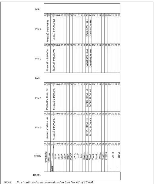
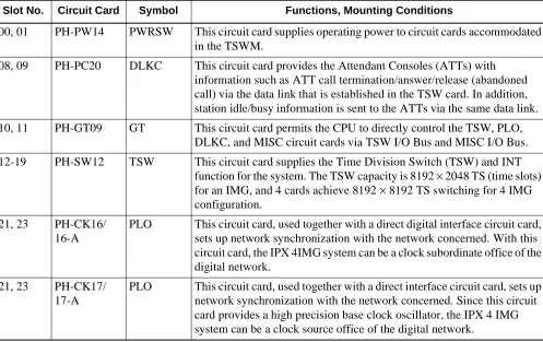
Figure 2-13 Controlling Circuit Cards in TSWM (Multiple IMG Configuration)
Table 2-7 Controlling Circuit Cards in TSWM (Multiple IMG Configuration)
Slot No. Circuit Card Symbol Functions, Mounting Conditions
00, 01 PH-PW14 PWRSW This circuit card supplies operating power to circuit cards accommodated
in the TSWM.
08, 09 PH-PC20 DLKC This circuit card provides the Attendant Consoles (ATTs) with
information such as ATT call termination/answer/release (abandoned call) via the data link that is established in the TSW card. In addition, station idle/busy information is sent to the ATTs via the same data link.
10, 11 PH-GT09 GT This circuit card permits the CPU to directly control the TSW, PLO,
DLKC, and MISC circuit cards via TSW I/O Bus and MISC I/O Bus.
12-19 PH-SW12 TSW This circuit card supplies the Time Division Switch (TSW) and INT
function for the system. The TSW capacity is 8192 × 2048 TS (time slots)
for an IMG, and 4 cards achieve 8192 × 8192 TS switching for 4 IMG
configuration.
21, 23 PH-CK16/
16-A
PLO This circuit card, used together with a direct digital interface circuit card,
sets up network synchronization with the network concerned. With this circuit card, the IPX 4IMG system can be a clock subordinate office of the digital network.
21, 23 PH-CK17/
17-A
PLO This circuit card, used together with a direct interface circuit card, sets up
network synchronization with the network concerned. Since this circuit card provides a high precision base clock oscillator, the IPX 4 IMG system can be a clock source office of the digital network.
TSWM
00 01 02 03 04 0506 07 08 09 1011 12 1314 15 16 1718 19 20 21 22 23