Power Electronics- A Trustworthy, Highly
Efficient Power Control and Conversion
Technology- An Overview
Md. Moyeed Abrar
1Assistant Professor, Dept. of CSE, K.B.N College of Engineering, Gulbarga, Karnataka, India1
ABSTRACT: The present state of the art in control and conversion of power using power electronics technology and its applications are emphasized. In recent years Power electronics technology has undergone a rapid revolution which is due to mainly two reasons. The first one is the development of fast semiconductor switches which are capable of switching quickly and handling high current/voltage. The second factor is the introduction of real time computer controllers that can implement advanced and complex control algorithms. The Power electronics revolution is giving us the ability to shape and control large amounts of power with ever increasing efficiency. It has already found an important place in modern technology and is now used in a great variety of high power products, including heat controls, light controls, motor controls, power supplies, vehicle propulsion systems and high voltage direct current (HVDC) systems. In this paper, the significance of power converters and its types are also presented.
KEYWORDS: Power electronics, Power electronics revolution, Power control, Power semiconductor devices, Power electronics converters.
I. INTRODUCTION
Power electronics is the art of converting electrical energy from one form to another in an efficient, clean, compact and robust manner for convenient utilisation. In the broader sense it implies that part of electronics used in electric power. This technology is used in the systems for control and regulation of electric power supplies and in the systems for the regulation of electric drives. It includes various types of electric power converters such as: converters of AC to DC current, DC to AC, DC to DC, AC to AC and converters of different types of energy (thermal, nuclear and light) into electric energy. Since most of the equipment that uses power electronics contains converters of some type, very often the concept of power electronics is understood as converter electronics.[1],[3]
In essence power electronics apparatus consists of the power part and the control part. The power component, serving for the transfer of energy from the source to the load consists of power electronic switches, electric chokes, transformers, capacitors, fuses and sometimes resistors. A combination of these elements combine to make different converter circuits adjusted to the mode of the primary supply and the character of the load. Energy losses within a converter should be as small as possible. Consequently, the semiconductor elements of the converter are mainly operating in the pulse (switching) mode. They could be either controllable (transistors, thyristor) or non- controllable (diodes). The control or information block controls the regulating (mostly switching) elements of the converter. The control or regulation is accomplished on the basis of the information the control block has collected from the power part of the apparatus. Mostly the information concerns the output voltage, load current or current/voltage of a critical element of the converter (e.g. transistor). The control block can functionally be a very complex electronic assembly consisting of either analog or digital elementary assemblies.
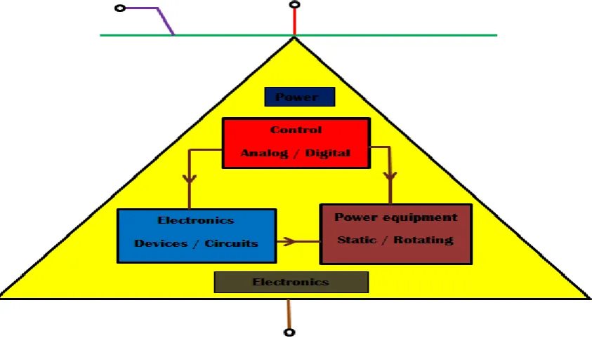
multidisciplinary nature. Presently, it is considered to be the most active stream in electrical power engineering. The versatile nature of power electronics is depicted in figure 1. [2], [5]
Fig 1.Multidisciplinary nature of Power electronics
Power electronics combine power, electronics and control. Power deals with the static and rotating power equipment for the generation, transmission and distribution of electric power. Electronics deals with the solid state devices and circuits for signal processing to meet the desired control objectives. Control deals with the steady-state and dynamic characteristics of closed loop systems. The figure 2 shows the interrelationship of Power electronics with power, electronics and control. [1]
The rest of the paper is organized into sections as follows. Section II deals with the evolution of Power electronics. Section III focuses on the control characteristics of Power electronic devices. Section IV describes the Power electronics converters. Section 5 includes the application areas of Power electronics technology. Finally section VI summarizes the paper and presents the concluding remark.
II. EVOLUTION OF POWER ELECTRONICS
The history of Power electronics began with the introduction of mercury arc rectifier in 1900. Then the metal tank rectifier, grid controlled vacuum tube rectifier, ignitron, phanotron and thyratron were introduced gradually. These devices were applied for power control until the 1950’s.The first electronics revolution began in 1948 with the invention of silicon transistor at Bell telephone laboratories by Bardeen, Brattain and Shockley. The next breakthrough in 1956 was also from Bell laboratories, the invention of PNPN triggering transistor, which was defined as a thyristor or silicon controlled rectifier (SCR).The second electronics revolution began in 1958 with the development of commercial thyristor by the general electric company. This was the new era of power electronics. Since then many different types of power semiconductor devices and conversion techniques have been introduced. Until 1970 the conventional thyristor had been exclusively used for power control in industrial applications. Since 1970, various types of power semiconductor devices were developed and became commercially available such as Triac, Gate turn off thyristor (GTO), Bipolar junction transistor (BJT), Power MOSFET, Insulated gate bipolar transistor (IGBT), Static induction transistor (SIT), static induction thyristor (SITH), and MOS- controlled thyristor (MCT). The latter four devices, which appeared in 1980’s, can be defined as modern. The Power electronics revolution has gained momentum since the late 1980’s and early 1990’s. A chronological history of Power electronics is shown in figure 3. [1], [5]
Fig.3 History of Power electronics
III. CONTROL CHARACTERISTICS OF POWER DEVICES
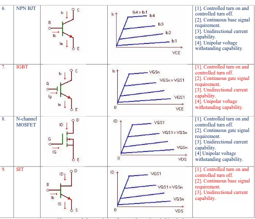
of these switching devices [1]. The table 1 shows the output voltages, control characteristics, circuit symbol and brief description of commonly used power switching devices.
SL.
NO
DEVICE
SYMBOL
CHARACTERISTICS
DESCRIPTION
1
.
Diode [1].There is no controlsignal.
[2]. Uncontrolled turn on and off
[3]. Unidirectional current capability.
2.
SCRThyristor
[1]. Controlled turn on and uncontrolled turn off. [2]. Pulse gate requirement. [3]. Unidirectional current capability.
3. GTO
Thyristor
[1]. Controlled turn on and controlled turn off.
[2]. Pulse gate requirement. [3]. Unidirectional current capability
[4]. Unipolar voltage withstanding capability.
4. TRIAC [1]. Controlled turn on in
both directions and uncontrolled turn off. [2]. Pulse gate requirement in both directions.
[3]. Bidirectional current capability.
5. LASCR [1].Controlled turn on and
uncontrolled turn off. [2]. Pulse gate requirement in the form of
photoelectrons.
Table 1 control characteristics of Power electronic switching devices.
From table 1, it is observed that various Power electronics switching devices exhibit different characteristics. Although majority of the devices posses controlled turn on and controlled turn off features. All discrete control devices regenerative or otherwise have three terminals. Two of these are the main terminals and the third form the control terminal. The amplification factor of all the devices (barring the now practically obsolete BJT) are quite high, though turn on gain is not equal to turn off gain. The drive circuit is required to satisfy the control terminal characteristics to efficiently turn on and turn off each of the devices.
IV. POWER ELECTRONICS CONVERTERS
A. Basics of Power Electronics converters
For the control of electric power or power conditioning, the conversion of electric power from one form to another is necessary and the switching characteristics of the power devices permit these conversions. The static power converters perform these functions. Power electronics converters are switch mode circuits that process power between two electrical systems using power semiconductor switches. The electrical systems can be either DC or AC. The power
6. NPN BJT [1]. Controlled turn on and
controlled turn off.
[2]. Continuous base signal requirement.
[3]. Unidirectional current capability.
[4]. Unipolar voltage withstanding capability.
7. IGBT [1]. Controlled turn on and
controlled turn off. [2]. Continuous gate signal requirement.
[3]. Unidirectional current capability.
[4]. Unipolar voltage withstanding capability.
8. N-channel
MOSFET
[1]. Controlled turn on and controlled turn off. [2]. Continuous gate signal requirement.
[3]. Unidirectional current capability.
[4] Unipolar voltage withstanding capability.
9. SIT [1]. Controlled turn on and
controlled turn off.
[2]. Continuous base signal requirement.
range can be from miliwatts, for example mobile phones to megawatts in electric power transmission system. Reliability of power converters become a key industrial focus. Electronic devices and control circuits must be highly robust in order to achieve a high useful life. A special accent must be set on the total efficiency of the power electronics circuits. Firstly, because of the economic and environmental value of wasted power and secondly, because of the cost of energy dissipated that it can generate. Power electronics converters have evolved rapidly both in terms of available electronic switching devices and converter topologies. Power converters exhibiting higher efficiency, faster response and better control is the need of the hour. [3], [7].
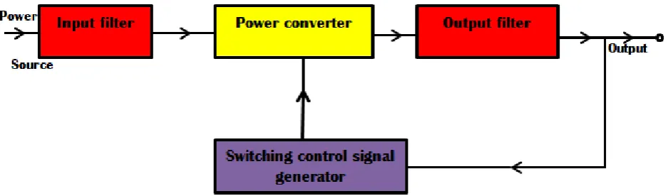
Power converters are used in a very wide range of low, medium and high power applications. The operation of the power converters is based mainly on the switching of power semiconductor devices; and as a result the converters introduce current and voltage harmonics into the supply system and on the output of the converters. These can cause problems of distortion of the output voltage, harmonic generation into the supply system, and interference with the communication and signalling circuits. It is necessary to introduce filters on the input and output of a converter system to reduce the harmonic level to an acceptable magnitude. The figure 4 shows the block diagram of a generalized power converter. [1]
Fig. 4 Generalized Power converter system.
B. Types of Power electronics converters.
There are four possible types of power electronics converters namely [1]AC to DC converters (controlled rectifiers).
[2] AC to AC converters (AC voltage controllers). [3] DC to AC converters (Inverters).
[4] DC to DC converters (DC choppers). AC to DC converters
[1] AC to DC converters
The process which converts AC to DC is known as Rectification; hence these converters are also called as Rectifiers. Usually the AC input to the circuit is a sinusoidal voltage source that operates at 120V, 60Hz or a 230V, 50 Hz, which are used for power distribution applications. The AC voltage is rectified into a unidirectional DC voltage, which can be used directly to supply power to a DC resistive load or control a DC motor. A rectifier is typically used as a front end circuit in many power system applications.
Rectification can be half wave or full wave. In the first case (half wave rectification), only one half of the input waveform can be employed to reach the desired output. Therefore only this half AC wave (positive or negative) is converted. Hence it is not useful for power transfer. The full wave rectification can convert the whole of the input waveform to achieve the constant output signal. Hence it becomes more efficient and useful.
[2] AC to AC converters
same fundamental input and output frequencies are called “AC controllers”. The conversion is from a fixed voltage fixed frequency (FVFF) to a variable voltage fixed frequency (VVFF). Applications include light dimmers and control of single phase AC motors that are typically used in home appliances.
When both voltage and frequency are changed, the circuits are called “cycloconverters”, which convert a fixed voltage fixed frequency (FVFF) to a variable voltage variable frequency (VVVF) and when fully controlled switches are used, this class of circuit is called “Matrix converter”. Another way of achieving AC to AC conversion is by using AC/DC and DC/AC through an intermediate DC link.
[3] DC to AC converters
These types of converters are also referred to as Inverters, which can obtain a certain amplitude and frequency of the AC voltage and/or current without using normally an intermediate DC stage. Inverters transform DC voltage from sources such as batteries, solar cells, or fuel cells or output of a rectifier into AC, for powering motor drives, providing stand-alone AC output, or interconnecting to the AC grid. Inverters can be usually classified according to their AC output as single phase or three phase and also as half and full bridge converters.
[4] DC to DC converters
These converters are electronic circuits that change the DC operating voltage or current. Normally, they are designed in order to transfer power from the input to the output in one direction. These converters are also known as “Choppers” or “switching regulators”. The circuit will change the level voltage available from a DC source such as a battery, solar cell or a fuel cell to another DC level, either to supply a DC load or to be used as an intermediate voltage for an adjacent power electronic conversion such as a DC to AC converter. DC to DC converters coupled together with AC to DC converters enable the use of high voltage DC (HVDC) transmission which has been adopted in transmission lines throughout the world.
V. APPLICATION AREAS OF POWER ELECTRONICS
Power electronics systems are found in virtually every electronic device. The application areas of Power electronics are illustrated.
[1] Inverters
Generally inverters are used in systems requiring direct conversion of electrical energy from DC to AC. DC to AC conversion is needed in various fields including motor drives, power conditioning, harmonic compensator and renewable energy grid integration. Inverters, also play a key role in many renewable energy applications. For photovoltaic purposes, the inverter which is mostly a PWM VSI gets fed by the DC electrical energy output of a photovoltaic module or array. The inverter then converts this into an AC voltage to be interfaced with either a load or utility grid.
Inverters are also used in other renewable systems, such as wind turbines. In these applications, the speed of the turbine usually varies causing changes in voltage, frequency and sometimes in magnitude. Here the generated voltage can be rectified and then inverted to stabilize frequency and magnitude.
[2] Hybrid electric vehicles (HEVs)
In hybrid electric vehicles (HEVs), power electronics is used in two formats: series hybrid and parallel hybrid. The differentiating factor between a series hybrid and a parallel hybrid is the relationship of electric motor to the internal combustion engine (ICE). In electric vehicles the devices used mainly consists of DC to DC converters for battery charging and DC to AC converters to power the propulsion motor. Power electronic devices are used in Electric trains to obtain power, as well as for vector control using pulse width modulation (PWM) rectifiers.
Power electronics systems are also employed in Motor drives that are found in pumps, blowers, and mill drives for textile, paper, cement etc. Drives may be used for power conversion and for motion control. Apart from these, power electronics technology is used in elevator systems. These systems may employ thyristor, inverters, permanent magnet motors or other hybrid systems that incorporates PWM systems and standard motors.
[3] Smart grids
such as information about the behaviour of suppliers and consumers, in an automated fashion to improve the efficiency, reliability, economics and sustainability of production and distribution of electricity.
[4] Grid voltage regulation
Power electronics systems can be used to help utilities adapt to the rapid increase in distributed, residential, commercial solar power generation. Relatively small scale ground or pole mounted devices create the potential for a distributed control infrastructure to monitor and manage the flow of power.
[5] Renewable energy systems
Electrical power generated by wind turbines and hydroelectric turbines by using induction generators can cause variances in the frequency at which power is generated. Power electronics devices are used in these systems to convert the generated AC voltages into high voltage direct current (HVDC). The HVDC power can be more easily converted into three phase power that is coherent with the power associated to the existing power grid. Through these devices the power delivered by these systems is cleaner and has a higher associated power factor.
VI. CONCLUSION
Power electronics technology has rapidly gone through dynamic revolution in recent years. We have seen in the evolution of Power electronics, the emergence and dynamic era of Power semiconductor devices in a short span of time. These devices constitute the heart of modern Power electronics. Its applications are rapidly expanding in the industrial, commercial, residential, transportation, utility, aerospace and military environments primarily due to the reduction of cost, size and improvement of performance. Power electronics will continue to be an enabling technology to address our future electricity needs Modern active and passive components such as silicon carbide (SiC) and gallium nitride (GaN) transistors open up new applications for both low and medium-voltage power converters. For example, the use of GaN semiconductors in resonant circuits allow power converters in the kW range with switching frequencies in the MHz range to be built. Medium voltage converters with high voltage SiC transistors are also made possible. Power electronics growth is expanding vastly due to advances in power semiconductor devices, advances in microelectronics (DSP, VLSI, microprocessor/ microcontroller, ASIC), new ideas in control algorithms and demand for new applications. The role of Power electronics on our society will tend to be as important and versatile as that of the information technology today.
REFERENCES
[1] Muhammad H. Rashid, “Power electronics circuits, devices and applications, second edition pp. 1-16.
[2] Bimal k. Bose, “Recent advances in power electronics”, IEEE Transactions on Power electronics, vol. 7, issue 1, pp. 1-5, 1992.
[3] Carolina Albea-Sanchez, “Control design for Electronic power converters” Automatic Institute National Polytechnique de Grenoble- INPG; Universidad de sevilla, 2010.
[4] Bose B.K, “Power Electronics and Motor Drives Recent Progress and Perspective”, IEEE Transactions on Industrial electronics, vol 56, issue 2, pp. 581-588, 2009.
[5] Ahmed F. zobaa, and Bimal K. Bose, “Renewable Energy, Global warming and Impact of Power electronics”, International conference on Renewable energies and Power qualities (ICREPQ’11), pp. 2-4, 2011.
[6] Van Wyk J.D., Lee F.C “On a Future of Power Electronics,” IEEE journal, vol. 1, pp. 59–72, 2013. [7] Branko Dokic, Branko Blanusa, “Power Electronics Converters and Regulators”, pp. 11-12, 2015.
[8] Sudipta Chakraborty, Marcelo G Simoes, William E. Kramer, “Power electronics for Renewable and Distributed Energy Systems”. Chapter 2, pp. 1-6
[9] Valery Vodovozov, “Introduction to Power electronics”, pp. 1-18, 2010.
BIOGRAPHY