Issue 2
PAGEPAC 6
V-5323006
by
PagePac
®INTRODUCTION
PagePac 6 is a compact, 6 watt, voice-paging system that integrates single-zone paging capability to your telephone system.
Dimensions/Weight
• 6.0”W x 2.5”H x 3.3”D (15.2cm x 6.4cm x 8.3cm) 2.0 lbs. (0.9 kg)
SPECIFICATIONS
FEATURES
• Connects to telephone system through standard modular telephone cords • Connects to voice coil speakers or horns
• Provides a 6-watt, voice coil output
• Controls background music provided from a line level source
• Includes 12VAC power supply that plugs into any standard 120VAC, 60 Hz outlet.
• Connects directly to telephone system page port (Page port must provide a dry contact closure.) • Requires separately purchased adapters for telephone systems without page port connections
(Trunk Adapter & PagePal)
INSTALLATION
There are several ways to connect PagePac 6 to your telephone system.
• For telephone systems equipped with a page port that has a contact closure, the PagePac 6 connects directly to the page port (see Figure 1).
Figure 1. PagePac® 6 Connections to Telephone System Equipped with Page Port and a Contact Closure
CONNECTING PAGEPAC
®6 TO A PAGE PORT WITH A CONTACT CLOSURE
INSTALLATION PROCEDURE
• PagePac 6 can be placed on a desk or shelf, or wall-mounted using the keyhole slot in the bottom of the unit.
• Circled numbers in Figure 2 correspond to the steps in the following installation procedures.
Figure 3. Connections to a Page Port with RJ11 Jack
After selecting a convenient location:
• Connect the page jack on the PagePac 6 to the telephone system page jack with a modular cord.
Note: If the page port has screw-type connections, use a half-modular cord to connect to the page port. The modular end of the cord connects to the PagePac 6 PAGE jack. On the other end of the cord, the green lead to page tip, and the red lead connects to page ring. The black and
PAGEPAC 6 SPEAKERS
PAGE PORT JACK NCOMING
ENTRAL OFFICE INES
TELEPHONE SYSTEM
TELEPHONE
with cc jack Page port
TELEPHONE SYSTEM
PAGE JACK
ESD COVERS NOT SHOWN
NOTE: Two ESD covers are provided for boththe SPEAKER/MUSIC IN terminal strip, and the AUX connector. Remove these covers prior to installation and replace when installation is complete.
TO 120 VAC 60 Hz
Note: The Canadian equivalent to the RJ11C connector is CA11A. Where applicable, CA11A is to be understood for other references to RJ11C in this manual.
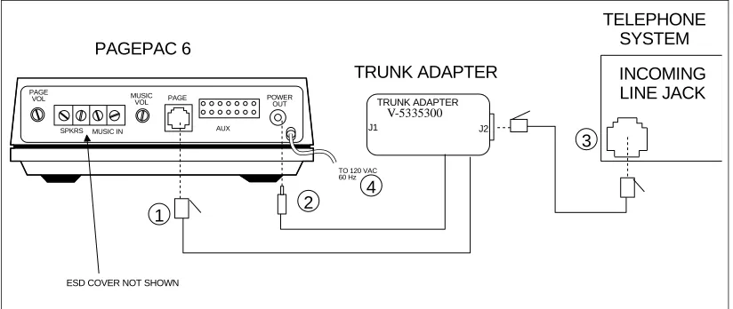
CONNECTING PAGEPAC 6 USING A PAGEPAC TRUNK ADAPTER
INSTALLATION PROCEDURE
After selecting a convenient location:
Note: Trunk Adapter connects PagePac 6 to vacant CO line port of telephone system. Circled numbers in Figure 3 correspond to the steps in the installation procedure.
1. Connect the Trunk Adapter modular cord to the PagePac 6 PAGE jack. 2. Connect the Trunk Adapter power cord to the PagePac 6 POWER OUT jack.
3. Connect the Trunk Adapter jack J2 to the telephone system trunk line jack (the jack which will be dedicated for paging) with a standard modular cord.
4. Plug the PagePac 6 power cord into a standard AC wall outlet.
Figure 3. Connections to a Line Jack Using the PagePac Trunk Adapter
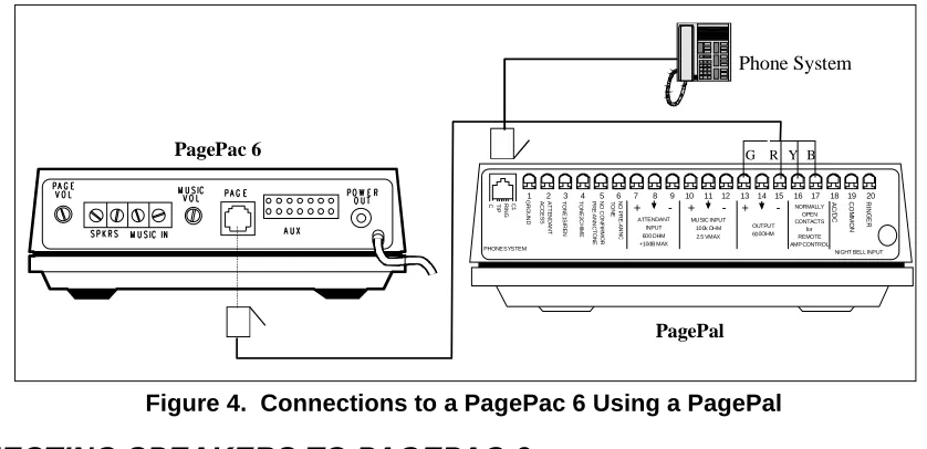
CONNECTING PAGEPAC 6 USING A PAGEPAL
INSTALLATION PROCEDURE
After selecting a convenient location:
Note: Add PagePal to PagePac 6 installation for Override page access, alert tones, CO port or Station port access, or night bell.
1. Connect terminal 13 of PagePal to green (pin 4) of PagePac 6. 2. Connect terminal 15 of PagePal to red (pin 3) of PagePac 6. 3. Connect terminal 16 of PagePal to yellow (pin 5) of PagePac 6. 4. Connect terminal 17 of PagePal to black (pin 2) of PagePac 6.
PAGEPAC 6
PAGE VOL
SPKRS MUSIC IN MUSIC
VOL PAGE POWEROUT
AUX
TRUNK ADAPTER
TELEPHONE SYSTEM INCOMING LINE JACK
TRUNK ADAPTER MODEL No 22050-900
J1 J2
ESD COVER NOT SHOWN
1 2
3 4
TO 120 VAC 60 Hz
Figure 4. Connections to a PagePac 6 Using a PagePal
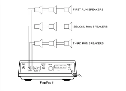
CONNECTING SPEAKERS TO PAGEPAC 6
Both standard speakers (indoor cone-type) and horn speakers may be used with PagePac 6. For best performance, use only the type speaker recommended for your situation (see Table 1), and do not exceed the number of speakers or speaker run length maximums shown in Table 2.
Table 1. Recommended Speakers
Table 2. Speaker Limitations
Paging Area Mounting Location Speaker Type Valcom Order No.
Open or Closed Office Areas, Conference Room, Etc.
On Wall or Ceiling Universal Cabinet V-5330105 Above the Ceiling Recessed Ceiling V-5330115 Hallways On Wall or Ceiling Universal Cabinet V-5330105 Private Office Placed on Desk or Wall Desktop or Wall V-5330110 Open Industrial Area or
Outdoors
On Wall or Pole at Least 15 Ft. Above Ground
1 Watt Horn V-5330010
Standard Indoor Speakers Horn Speakers
Total Speakers 24 @ 1/4W 6 @ 1W Speakers Per Run1 5 1 Maximum Length of Speaker Run (24
AWG Copper Wire)
Maximum Lenght of Speaker Run (22 AWG Copper Wire)
100 Feet
500 Feet
100 Feet
300 Feet
Notes: 1. A run is a line of one or more speakers that connects directly to PagePac 6. If using both horns and standard speakers, each horn counts as four standard speakers.
1 2 3 4 5 6 7 8 9 10 11 12 13 14 15 16 17 18 19 20R
IN G E R C O M M O N A C /D C NORMALLY OPEN CONTACTS for REMOTE AMP CONTROL OUTPUT 600OHM + + + -MUSIC INPUT 100k OHM 2.5 VMAX ATTENDANT INPUT 600 OHM +10dB MAX N O P R E -A N N C T O N E N O C O N F IR M O R P R E -A N N C T O N E T O N E 2C H IM E T O N E 1S IR E N A T T E N D A N T A C C E S S G R O U N D C1 R IN G T IP C
PHONE SYSTEM NIGHT BELL INPUT
R
G Y B
PagePac 6
PagePal
Figure 5. Connecting Speakers
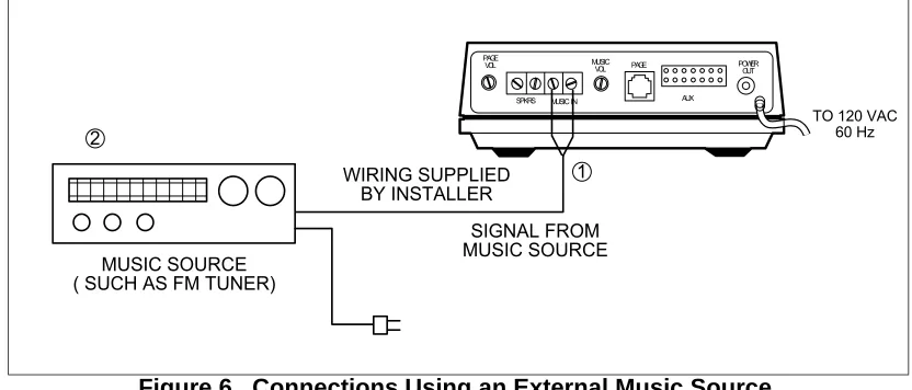
CONNECTING MUSIC SOURCE TO PAGEPAC
®6
REQUIRED MATERIALS
• An external music source, such as FM tuner, tape deck, leased source, etc.
• Wire for making connection between music source and PagePac 6. Speaker wire (24 AWG) may be used for this purpose.
INSTALLATION PROCEDURE
1. Connect audio output of music source (see Figure 6) to the PagePac 6 MUSIC IN terminals. 2. Turn on the music source.
3. Select a station and set the volume control on the music source, then use the MUSIC VOL control on the PagePac 6 to adjust the volume, as described in Operation Section.
NOTES:
If, during a page, you hear music in the speakers or phone, reverse the position of the wires on the MUSIC IN terminals.
PagePac 6
FIRST RUN SPEAKERS
SECOND RUN SPEAKERS
Figure 6. Connections Using an External Music Source
Those who use paging systems to rebroadcast copyrighted music are required to obtain licenses from and pay fees to copyright owners. This usually involves obtaining licenses and paying fees to either ASCAP and/or BMI (American Society of Composers, Artists and Producers, Broadcast Music Inc.). It is the user's obligation to obtain any license required and pay any fees.
Whenever possible, the PagePac 6 paging system should be plugged into the same AC power receptacle as the voice system.
OPERATION
Paging procedures differ depending on the requirements of your telephone system and how it is con-nected to PagePac 6. If your system is concon-nected using a PagePac® 6 Port Saver, pay particular atten-tion to the pertinent instrucatten-tion secatten-tion below.
PAGING WHEN CONNECTED THROUGH A PAGE PORT OR A PAGEPAC
®TRUNK ADAPTER
The exact procedure for paging on your particular telephone system is explained in the user's manual that accompanies the telephone system. In general, though, the steps are as follows:
1. Access the paging function as required by your telephone system. If PagePac 6 is connected through a page port, you will probably push a button or dial a code to access the function. If
PagePac 6 is connected through a PagePac Trunk Adapter, you will follow your telephone system's requirements for accessing the line reserved for paging.
2. Make the page.
3. Replace the telephone handset gently (remember you are still connected to the loudspeaker). This will prevent loud noises from being heard over the paging system.
ADJUSTING PAGE AND MUSIC VOLUME
Volume controls on the rear of PagePac 6 allow you to adjust the volume of paging and background music independently.
1
P A G E V O L
S P K R S M U S I C I N
M U S I C
V O L P A G E P O W E RO U T
A U X
T O 1 2 0 V A C 6 0 H z
2
W I R I N G S U P P L I E D B Y I N S T A L L E R
S I G N A L F R O M M U S I C S O U R C E M U S I C S O U R C E
To adjust background music volume, turn the MUSIC VOL control clockwise to increase or counterclock-wise to decrease volume. If you do not use background music, turn the MUSIC VOL control fully coun-terclockwise.
Note: PAGE VOL should be adjusted first, then MUSIC VOL.
MAINTENANCE
The PagePac 6 contains no user-serviceable parts, and should be repaired only by authorized person-nel. There are several types of installation and maintenance plans available from Valcom or your dealer. For information or warranty service, call your Valcom sales representative or authorized dealer.
TROUBLESHOOTING PROCEDURES
If your paging system fails to operate properly, follow the suggestions in the “Trouble Analysis Table” (see Table 3) before calling for professional assistance.
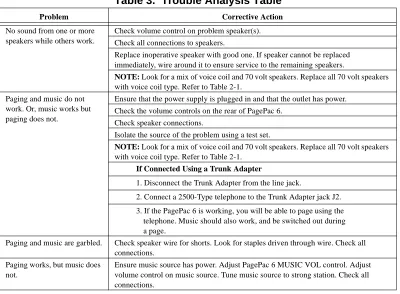
Table 3. Trouble Analysis Table
If, for any reason, you need to know the pinouts for the modular jacks on the PagePac 6, pinout informa-tion is given in Tables 4.
Problem Corrective Action
No sound from one or more speakers while others work.
Check volume control on problem speaker(s). Check all connections to speakers.
Replace inoperative speaker with good one. If speaker cannot be replaced immediately, wire around it to ensure service to the remaining speakers.
NOTE: Look for a mix of voice coil and 70 volt speakers. Replace all 70 volt speakers with voice coil type. Refer to Table 2-1.
Paging and music do not work. Or, music works but paging does not.
Ensure that the power supply is plugged in and that the outlet has power. Check the volume controls on the rear of PagePac 6.
Check speaker connections.
Isolate the source of the problem using a test set.
NOTE: Look for a mix of voice coil and 70 volt speakers. Replace all 70 volt speakers with voice coil type. Refer to Table 2-1.
If Connected Using a Trunk Adapter
1. Disconnect the Trunk Adapter from the line jack.
2. Connect a 2500-Type telephone to the Trunk Adapter jack J2. 3. If the PagePac 6 is working, you will be able to page using the
telephone. Music should also work, and be switched out during a page.
Paging and music are garbled. Check speaker wire for shorts. Look for staples driven through wire. Check all connections.
Paging works, but music does not.
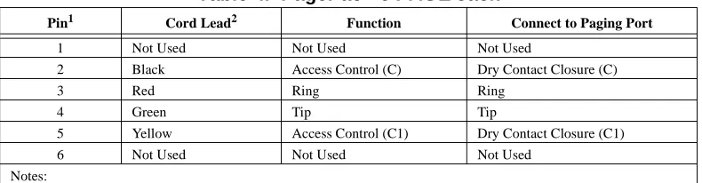
Table 4. PagePac® 6 PAGE Jack
TECHNICAL ASSISTANCE
When calling, have a VOM and a telephone test set available and call from the job site. Call (540) 427-3900 and ask for PagePac Technical Support, or call (540) 427-6000 for Valcom 24-hour Automated Support or visit our websites at http://www.pagepac.com and www.valcom.com.
Should repairs be necessary, attach a tag to the unit clearly stating company name, address, phone number, contact person, and the nature of the problem. Send the unit to:
Valcom, Inc. PagePac® Repair Dept.
5614 Hollins Road Roanoke, VA 24019-5056
FCC REGULATIONS PERTAINING TO THIS EQUIPMENT
FCC (PART 15)
Radio Frequency Interference
The PagePac 6 generates, and uses radio-frequency energy and, if not installed and used in strict accor-dance with the manufacturer’s instructions, may cause interference to radio and television reception. Testing has been conducted for compliance with the limits for a Class B device in accordance with the specifications in Subpart J of Part 15 of the FCC Rules. This testing is designed to provide reasonable protection against such interference. However, there is no guarantee that interference will not occur in a particular installation. If this equipment does cause interference to radio or television reception, which can be determined by turning the PagePac unit off and on, the user is encouraged to try to correct the interference by one or more of the following measures:
• Reorient the radio or TV receiving antenna.
• Relocate the PagePac with respect to the radio or TV receiver or vice-versa
• Plug the PagePac 6 into a different outlet so that it and the radio or TV receiver are on different branch circuits.
If necessary, the user should consult the dealer or an experienced radio/television technician for addi-tional suggestions. The user may find the following booklet, “How To Identify and Resolve Radio-TV Interference Problems,” helpful. This booklet was prepared by the Federal Government printing Office, Washington, DC 20402. Stock order No. 004-000-00345-4.
FCC (PART 68)
Pin1 Cord Lead2 Function Connect to Paging Port
1 Not Used Not Used Not Used
2 Black Access Control (C) Dry Contact Closure (C)
3 Red Ring Ring
4 Green Tip Tip
5 Yellow Access Control (C1) Dry Contact Closure (C1) 6 Not Used Not Used Not Used
Notes:
1. Connection and Use with Nationwide Telephone Network
The FCC requires that you connect your telephone equipment to the nationwide telephone network through a modular telephone outlet or jack. The modular telephone outlet or jack to which the equipment must be connected is a USOC RJ11C.
Registered equipment may not be used with Coin Telephone Lines. Equipment may be used with Party Lines in areas where state tariffs permit such connections and when equipment is adaptable for such use.
2. Information You May Need to Supply the Telephone Company
Upon request of your local telephone company, you are required to provide them with the following infor-mation.
A. The lines to which you will connect the telephone equipment.
Note: In Canada, the Document Registration Number appears on the maple-leaf label and the Load Number is under the maple-leaf label.
B. The FCC registration number and Ringer Equivalence Number (REN). Both numbers are listed on the equipment label. The REN is useful to determine how many devices you may connect to your tele-phone line and still have them ring when your teletele-phone lines is called. In most, but not all, areas, the sum of all RENs per line should be 5 or less. You may want to contact your local telephone company. The local telephone company must also be notified upon final disconnection of the equipment from the local telephone company lines.
CSA REGULATIONS PERTAINING TO THIS EQUIPMENT
This product is UL Listed and CSA Certified.
NOTICE:
The Canadian Department of Communications label identifies certified equipment. This certification means that the equipment meets certain telecommunications network protective operational and safety requirements. The Department does not guarantee the equipment will operate to the user’s satisfaction.
Before installing this equipment, users should ensure that it is permissible to be connected to the facili-ties of the local telecommunications company. The equipment must also be installed using an accept-able method of connection. In some cases, the company’s inside wiring associated with a single line individual service may be extended by means of a certified connector assembly (telephone extension cord). The customer should be aware that compliance with the above conditions may not prevent degra-dation of service in some situations.
Users should ensure for their own protection that the electrical ground connections of the power utility, telephone lines and internal metallic water pipe system, if present, are connected together. This precau-tion may be particularly important in rural areas.
SECONDARY CIRCUIT PROTECTION
IMPORTANT INFORMATION
This equipment is for use on telephone wiring containing a secondary circuit protector. This paging equipment requires a secondary circuit protector where applicable (see Figure 7).
The secondary circuit protector must be located between the primary protector and the paging equip-ment. Refer to the Safety Information below.
Figure 7. Example Configuration Requiring Secondary Protection When Paging Equipment is Connected Directly to the Telephone Network
SAFETY INFORMATION
• The secondary circuit protector is used when connecting paging equipment directly to telephone lines that may be exposed to high voltage power lines.
• Never install telephone wiring during a lightning storm.
• Never install telephone jacks in wet locations unless the jack is specifically designed for wet locations. • Never touch uninsulated telephone wires or terminals unless the telephone line has been
disconnected at the network interface.
• Use caution when installing or modifying telephone lines. • Use appropriate Valcom approved device.
CAUTION: