IoT based Gateway for Electricity Energy
Meter by using ZigBee
Modi Rakeshkumar. D1, Sukhadia Rakesh. P.2
M.E Student (Electrical Power System)], Dept. of Electrical Engg., L. D. R. P.-ITR, Gandinagar, Gujarat, India1
Lecturer, Dept. of Electrical Engg., L. D. R. P.-ITR, Gandinagar, Gujarat, India2
ABSTRACT: This system focus on the design and implementation of IoT based Gateway for Electricity energy meter by using zigBee (smart electricity energy meter). This design can be eliminate the man power involvement to maintain the electricity. The consumers of electricity need to pay as per the utilization of electricity on schedule, somehow consumers fail to pay, the transmission of electricity can be turned off from the distant server automatically. Energy meter provides provision to the consumers that they can monitor the energy consumption in units by using web page providing device IP address. Energy meter consists theft detection unit will notify company side in the event of meter tempering or theft practice occur in energy meter and also it will send information regarding theft detection by using zigBee and the theft detected will be displayed on the terminal screen or window of the company side. IoT operation can be performed by GSM device which sending energy meter data to the web page through the IP address.
ZigBee is a new global standard for wireless communications with the characteristics of low-cost, low power consumption, and low data rate. It has a good market in wireless meter reading. The design and implementation of a ZigBee-based wireless automatic meter reading system are proposed in this paper. The experimental results show that the design can meet the basic needs of automatic meter reading with flexibility and expansibility. It can act as a platform of wireless monitor system and supplies a new hardware design approach for wireless ZigBee networks.
IoT based Gateway for Electricity energy meter by using zigBee is an automated Meter reading systems are a invaluable technological advancement that can lead to a better standard of living, owing to the fact that metering has become a part and parcel of our mundane lives. It solves many issues of the traditional meter reading system like need for human resources, efficiency, accuracy, delayed work, unavailability of customer during metering visit by employee, etc. Moreover it is more economical and helps to save energy in a more efficient and effective way. Furthermore it has a very notable advantage of having the ability to predict the energy demands of the future, starting from every household to the entire planet. Automated meter reading systems have been implemented using many different technologies like GSM, ZigBee.
KEYWORDS:IoT(Internet of Things), Gateway, ZigBee, Microcontroller, GSM.
I.INTRODUCTION
In the current scenario, the world facing cyrisis of energ. The effective solution of this burning problem is to monitor and control the usage of the power. One effort is to fight against this energy or power crisis is to save the power or reduction of the power usage in home appliances.
On the power system the numbers of consumers are increasing rapidly day by day indirectly we can say the burden on the power system in increasing. The solution of this problem is provide ideal solution at consumer end. Now a days we have concept regarding this is IoT (Internet of Things) based Gateway for Electricity Energy Meter by using ZigBee (smart electricity energymeter) which works smartly in the sense that it can provide other services like information about electricity theft by employing theft detection unit and ZigBee.
see or monitor the energy consumption in MWh on its display window. This display from a web page providing device IP address. The authorized fellow of the supplier company get information when tampering occurring in the energy meter, for this facility there is theft detection unit or module connected with energy meter. To transfer the information regarding theft and tempering of energy meter used zigBee and the indication theft will be displayed on the window on the supplier end.
II.SYSTEM DESIGN AND CONCEPT
The concept of Internet of Things (IoT) from it initial stage changing the current Internet into well featured upcoming internet. At present there are billions of gadgets (approximately nine billions) interconnected gadgets and one prediction is that it will reach up to fifty billions gadgets in 2020.
The IoT based smart energy meter comprises mainly 3 modules (units).
1) IoT (Internet of Things)
2) Zigbee (Wireless communicator) 3) Gateway
Figure 1. Conceptual Block Diagram of Proposed System
In the current scenario the need is to access the characteristic of device remotely but in a reliable manner. To achieve the characteristic of device remotely we need to connect a device (here energy meter) to internet by providing IP address to it.
III.INTERNET OF THINGS (IoT)
• The tem Internet of Things (IoT) was first used by Kevin Ashton in 1999.
• The IoT also called the Internet of Objects refers to wireless network between objects, usually the network will be wireless and self configuring such as household appliances.
• IoT refers to the concept that the internet is no longer just a global network for people to communicate with one another using computers, but it is a platform for device to communicate electronically with the world around them.
• The term Internet of Things has come to describe a number of technologies and research disciplines that enable the internet to reach out into the real world of physical objects.
• Things having identities and virtual personalities operating in smart spaces using intelligent interface to connect and communicate within social, environmental and user context.
• The Internet of Things, also called the Internet of Objects, refers to a wireless network between objects, usually the network will be wireless and self configuring, such as household appliances.
The characteristics of Internet of Things (IoT) are as follows.
• Its structure is flexible.
• It consist semantic sharing.
• It can access complex Technologies.
• It consist Ambient Intelligence.
Internet of Things (IoT) can be applied in various field are as follows.
Education
Management
Logistics
Retail
Pharmaceuticals
Food
IV. ZIGBEE
ZigBee is a new global standard for wireless communications with the characteristics of low-cost, low power consumption, and low data rate. ZigBee technology is a bidierectional wireless communication technology of short distance, low complexity, low cost, low power consumption, and low data rate, mainly used in automatic control. It mainly works on 2.4GHz ISM band with 20~250kbit/s data rate, 100m~1.5km maximum transmission range, and a typical 100m distance.
The technical features include:
(1) Security: ZigBee provides data integrity check and authentication, and uses AES-128 security algorithm. Each application has the flexibility to determine its safety properties.
(2) Reliability: It uses collision avoidance mechanism, and at the same time it reserves a dedicated time slot to require a fixed bandwidth of the communication service, avoid the competition and conflicts when data is sent. MAC layer uses a full confirmation of data ransfer mechanisms, and each packet of data sent must wait to receive confirmation.
(3) Low cost: the initial cost of module estimates about US$6, and soon will fall between US$1.5 and US$2.5, and ZigBee Protocol is free of royalties.
(4) Power saving: as the duty cycle is very short, transmitting and receiving information has lower power consumption, and using the hibernation mode, ZigBee technology ensures that two N size batteries can support from 6 months to 2 years. Of course, different applications have power different power consumptions.
(5) High network capacity: a ZigBee network can accommodate a maximum of 65536 devices.
(6) Short delays: enhanced communication delays for delay-sensitive applications. Communication delay and sleep wake up time delay are very short. Typical device search delay is 30ms, typical sleep wake up time delay is 15ms, and active channel access delay is 15ms.
Figure – 2 ZigBee Module
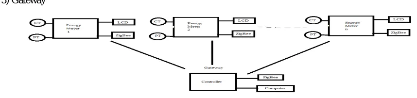
V. GATEWAY
• In this type of electricity energy meter Gateway is used as a data transmitter device from energy meter to the server at the supplier side.
• Here two kinds of possibility for gateway.
1) Gateway is merged with electricity energy meter in built 2) Gateway as a separate module for each unit.
• Here we need to provide provision of Gateway as a separate module so it can be applicable to already existing electricity energy meter so it eliminates the need of change all the existing energy meters.
• Now we can merged the Gateway in the electricity energy meter (in built) for new manufacturing meters.
VI.PROPOSED SYSTEM (CONSUMER’S END)
The system consist major component at consumer end like PIC micro-controller PIC18F4520, Voltage sensor [P.T.], Current sensor [C.T.], Tamper detection switch, Reset Emergency circuit, Crystal oscillator, LCD, circuitry etc as shown in below figures.
Figure-3 Block Diagram of proposed system at Consumer’s End
VII.PROPOSED SYSTEM (SUPPLIER’S END)
The system consist major component at supplier end like PIC micro-controller PIC18F4520, LCD, circuitry, Buzzer, GSM module, P.C. etc as shown in below figures.
Figure-4 Block Diagram of proposed system at Supplier’s End
VIII.PIC MICROCONTROLLER (PIC 18F4520)
A microcontroller is a kind of miniature computer that you can find in all kinds of Gizmos. The microcontroller that has been used for this project is from PIC series. PIC microcontroller is the first RISC based microcontroller fabricated
LCD
To Webserver GSM/
GPRS Voltage
Sensor
[P.T.] PIC
microcontroller Zigbee Tamper
DetectionSw itch
Current Sensor
[C.T.]
in CMO that uses separate bus for instruction and data allowing simultaneous access of program and data memory. . Easy Programming and Erasing are other features of PIC 18F4520.
Operating frequency
Program memory
I/O ports Timers
DC to 40 MHz
32768 Bytes A,B,C,D,E 4
Figure – 5 Pin Configuration of PIC 18F4520
IX.LCD 16 X 2
Alphanumeric displays are used in a wide range of applications, including palmtop computers, word processors, photocopiers, point of sale terminals, medical instruments, cellular phones, etc. The 16 x 2 intelligent alphanumeric dot matrix displays is capable of displaying 224 different characters and symbols. This booklet provides all the technical specifications for connecting the unit, which requires a single power supply (+5V).
LCD (Liquid Crystal Display) screen is an electronic display module and find a wide range of applications. A 16x2 LCD display is very basic module and is very commonly used in various devices and circuits. These modules are preferred overseven segments and other multi segmentLEDs. The reasons being: LCDs are economical; easily programmable; have no limitation of displaying special & even custom characters (unlike in seven segments), animations and so on.A16x2 LCD means it can display 16 characters per line and there are 2 such lines. In this LCD each character is displayed in 5x7 pixel matrix. This LCD has two registers, namely, Command and Data. The command register stores the command instructions given to the LCD. A command is an instruction given to LCD to do a predefined task like initializing it, clearing its screen, setting the cursor position, controlling display etc. The data register stores the data to be displayed on the LCD. The data is the ASCII value of the character to be displayed on the LCD. Click to learn more about internal structure of LCD.
Figure – 6 Pin Configuration of LCD 16X2
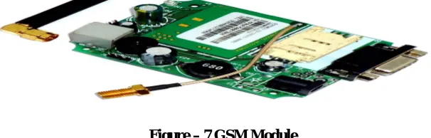
X.GSM SIM300
develop embedded applications. Applications like SMS Control, data transfer, remote control and logging can be developed easily.
The modem can either be connected to PC serial port directly or to any microcontroller. It can be used to send and receive SMS or make/receive voice calls. It can also be used in GPRS mode to connect to internet and do many applications for data logging and control. In GPRS mode you can also connect to any remote FTP server and upload files for data logging. This GSM modem is a highly flexible plug and play quad band GSM modem for direct and easy integration to RS232 applications. Supports features like Voice, SMS, Data/Fax, GPRS and integrated TCP/IP stack. Designed for global market, SIM300 is a Tri-band GSM/GPRS engine that works on frequencies EGSM 900 MHz, DCS 1800 MHz and PCS1900 MHz. SIM300 provides GPRS multi-slot class 10 capabilities and support the GPRS coding schemes CS-1, CS-2, CS-3 and CS-4.
With a tiny configuration of 40mm x 33mm x 2.85 mm , SIM300 can fit almost all the space requirement in Yourapplication, such as Smart phone, PDA phone and other mobile device.
The physical interface between SIM300 and the mobile application is through a 60 pins board-to-board connector, which provides all hardware interfaces from module to customers’ boards except the RF antenna interface.
Figure – 7 GSM Module
XI.WORKING OF PROPOSED SYSTEM
Total power consumed reading will be transmitted through ZigBee transmitter.
Controller will detect if any tamper is done to meter and immediately data will be transmitted to gateway for alert or alarm system.
LCD is implemented for local display.
Energy meter data will be transmitted over zigBee based communication network.
Zigbee will receive the data transmitted from other side of the system and provide that data to the controller.
Controller will upload the received data to webserver using GSM modem.
All data will be written to webserver using in GSM modem.
The IoT based Gateway for Electricity Energy Meter by using ZigBee has the PIC microcontroller as Central
Processing Unit. The whole system is interfaced with PIC microcontroller. The ZigBee modem is serially connected with the controller which is the major communication module between User and provider. The GSM uses its own network for the transfer of information. Special coding in embedded c is used for programming PIC microcontroller using programmer Hardware along with MP-LAB IDE software. The relay acts as switching device to cut off and restore power supply. The LCD is interfaced to microcontroller using parallel port connection. In this system the Microcontroller based system continuously records the readings and the live meter reading can be sent to the Electricity department on request. This system also can be used to disconnect the power supply to the house in case of non-payment of electricity bills.
This module will reduce the burden of energy providing bye stablizing the connection easily and no theft of power will takes place. The LCD display will display the used amount and balance amount that can be used.
XII. COMPARISON BETWEEN EXISTING AND PROPOSED ELECTRICITY ENERGY METER READING SYSTEM
A. EXISTING ELECTRICITY ENERGY METER READING SYSTEM :
As we know in our country the electricity energy billing duration is either end of one month or end of two months. During the month electricity consumer cannot how much power consumed, they can know at the end of one or two months when the bill issue. The major drawback of this method is use cannot manage the power consumption. Another disadvantage of this system is tempering with energy meter can be done easily and such practices are happening and increasing rapidly which is one of the major cause of power crises.
B. PROPOSED ELECTRICITY ENERGY METER READING SYSTEM :
In this method we tries to eliminate the drawback and limitations of existing electricity energy metering method. In this method there is a provision for the consumer that they can see their power consumption time to time so they have an opportunity to manage the power consumption as they desire. This method is not only provide the facility to consumer end but also it is more helpful to supplier end also. If the consumer fails to pay their electricity billed amount within the time period mentioned by the supplier, the supplier can be disconnect the power automatically from the distant end. This system eliminate the physical disconnection procedure at consumer site so it will be helpful to avoid conflict between consumer and supplier at the time of disconnection. This system can also provide the facility of the reconnection of the power from the distant end. Another major advantage of this system is that it provides the information at the event meter tempering and power theft. Such information will be very useful to control the practices of power theft and reduce the power crises.
XIII.ADVANTAGES AND DISADVANTAGES OF PROPOSED SYSTEM
A. ADVANTAGES :
• It provides telemetering service and eliminate the man power requirement for metering.
• It can reduce revenue loss to supplier company by controlling theft detection.
• It makes easy to access information of energy consumption from energy meter through IoT.
• It provides disconnection of service to consumers from remote.
• It provides LCD display energy consumption.
• It saves time for meter reading and prevent mistakes up to some extent.
B. DISADVANTAGES :
• The main disadvantage of this proposed system has recurring cost every month.
• The system must have sufficient mobile network coverage.
XIV.SIMULATION AND RESULT ANALYSIS
In this section, we demonstrated the experimental results of the proposed system. The monitoring and management interface of the wireless automatic meter reading system in this research is coded with the Visual Basic Program language developed by Microsoft It consist of different blocks like microcontroller block, zigBee, precision rectifier, EB meter to calculate power consumed, current and voltage transformer for calculating voltage and current in use. At the server end, it receives electric meter data and the load was connected.It transfers measured data by ZigBee module in RS-232communication format to complete the automatic wireless meter system.The user can monitor the power consumption details on the LCD. The system communicates with the remote station through communication module. Outputs of average real power information based on the load are displayed on the LCD. Depending on the data received from the energy meter module, it sends information of the user meter to remote place through wireless communication module. In addition to that, the same information is sent to the user through LCD.
XV.CONCLUSION
The successful development of the IoT based Gateway for Electricity Energy Meter by using ZigBee is described in this article is based on the high performance, extremely low power consumption, high level of integration, and low price of ZigBee technology. The technology has strong market competitiveness. ZigBee wireless meter reading system uses short-range wireless communication and computer network technologies to read and process metering data automatically. Wireless automatic meter reading technology can not only save human resources, but also improve the accuracy and instantaneity of the meter reading. It enables management sector to timely and accurately access power consumption messages. Moreover, no cabling is required with relatively economical investment. For the proposed IoT based Gateway for Electricity Energy Meter by using ZigBee system, wireless communication links can be quickly built, engineering period significantly shortened, and it has better scalability compared to a wired system. If a fault occurs, simply checking wireless data module can quickly find it out and restore the system in normal operation. This system can not only reduce the shortcomings of traditional metering system but will reduce manpower requirements. It avoids the human intervention, provides efficient meter reading and reduce the maintenance cost.IoT based Gateway for Electricity Energy Meter by using ZigBee is designed to get telemetering , theft detection and supplier can disconnect service to the consumers in the event of meter tempering or un authorized use of electricity.
REFERENCES
[1] DarshanIyer, Dr. K. A. RadhakrishnaRao“IoT based energy meter reading, Theft detection and disconnection using PLC modem and power optimization.” IJAREEIE conference proceeding.
[3] PoonamBorle, AnkithaSaswadhar, DeepaliHiwarkar, Rupali S. Kali, “Automatic meter reading for electricity”, International Journal of Advance Research in Electrical, Electronics and Instrumentation Engineering, vol.2, no.3, pp.982-987, March-2003.
[4] Andrea Zanella, Senior member, IEEE, Nichola Bui, Angelo Chastallani, Lorenzo vangelista, senior member IEEE and mischellzorzi, Fellow IEEE, “Internet of Things for smart cities”, IEEE Internet of Things Journal, vol.1, no.1, pp-22-32, February-2014.
[5] Landi C., Dipt. d.Ing.,dell inf. Secondauniv. di Napoli, Aversa Italy, Morela, P.; lannilo G, “ARM based energy management system using smart meter and web server”, IEEE Instrumentation and Measurement Technology conference Binjiang, pp.1-5, May-2011.
[6] Steven Lanzisera, Member IEEE, Andrew R. Weber, Anna Liao, Dominic Pajak, and Alan K. Meier, “Communication power supplies:Bringing the internet to the ubiquitous Energy Gateways of Electronics Devices”, IEEE Internet of things Journal, vol.1, no.2, pp.153-160, March-2014. [7] T.Kamalesh,M.VedaChary,”Post-paid wireless meter system for automatic power controlling and consumption billing applications”. [8] Li Quan-Xi,LiGang,”Design of remote automatic meter reading system based on Zigbee and GPRS”.