Multi-Stage Fault Attacks on Block Ciphers
Philipp Jovanovic, Martin Kreuzer, Ilia Polian
Fakult¨at f¨ur Informatik und Mathematik Universit¨at Passau
94032 Passau, Germany
{Philipp.Jovanovic, Martin.Kreuzer, Ilia.Polian}@uni-passau.de
Abstract—This paper introduces Multi-Stage Fault Attacks, which allow Differential Fault Analysis of block ciphers having independent subkeys. Besides the specification of an algorithm implementing the technique, we show concrete applications to LED-128 and PRINCE and demonstrate that in both cases approximately 3 to 4 fault-injections are enough to reconstruct the full 128-bit key.
Keywords-cryptanalysis; Differential Fault Analysis; LED-128; lightweight block cipher; Multi-Stage Fault Attack; PRINCE;
I. INTRODUCTION
Small mobile and embedded devices, like RFID chips and nodes of sensor networks, increasingly find their way into our everyday life. In many cases they are utilised to process sensitive (personal) data, for example in the form of financial and medical information, which requires protection against unauthorised access. The design of cryptographic primitives that provide acceptable security and can be implemented on devices with strictly limited resources is very challenging and has raised significant interest in the last few years. Numerous new algorithms have been proposed to address those problems including lightweight block ciphers such as PRESENT [3], PRINCE [5], and LED [7]
On the other hand, with the ubiquitous proliferation and easy accessibility of such devices, new types of attacks, known as side-channel analysis, examine the implementa-tion of cryptographic primitives.Differential Fault Analysis
[2], which combines fault attacks [4] with differential crypt-analysis [1], is particularly effective and was employed for successful attacks on a variety of ciphers, including Trivium [8], AES [11] and LED-64 [9]
Symmetric ciphers encrypt information using asecret key
k. Classical ciphers, such as DES or AES, incorporate a
key schedule which generates a number of subkeys from k using certain transformations. The subkeys are used for individual steps, or rounds, of the encryption algorithm. Several state-of-the-art ciphers have no key schedule: their subkeys are simply independent parts of k. For example, LED-128 uses a 128-bit key k = k0 k k1 which consists
of two 64-bit subkeys k0 and k1 that are used during
encryption. One argument for avoiding the key schedule is the lower cost of hardware implementations. Furthermore, several attacks utilise the dependencies between different rounds of the algorithm introduced by the key schedule; such dependencies are avoided when subkeys are independent.
In this paper, we propose a generic differential fault analysis technique for ciphers with sindependent subkeys. The attack is mounted in s stages, where each stage pro-duces a set of candidates for one subkey. The number of fault injections per stage is variable; in general, performing more fault injections will narrow down the set of subkey candidates. We introduce an algorithm which minimises the overall number of required fault injections while producing
a number of key candidates that can be analysed by brute-force search. It can be regarded as a generalisation of the “peeling-off” approach [6], where the last subkey is derived and the cipher is reduced by partial decryption using that subkey. In contrast to [6], our algorithm does not require the definite knowledge of the last subkeys but works with a (comparatively small) set of subkey candidates that include the actual (correct) subkeys together with a number of wrong guesses. The algorithm uses special threshold variablesτi
to adaptively distribute the fault injections between stages such as to keep the overall effort feasible.
We report the application of the algorithm to complete attacks against two recent ciphers: LED-128 and PRINCE. The attack on LED-128 is the first one based purely on fault injections. The attack mentioned in [9] assumed the capability of the adversary to temporarily set one of the 64-bit subkeys to 0, in addition to applying controlled fault injections to the hardware. The attack on PRINCE has been developed independently and simultaneously by a different group and published online [10]. Note that these attacks on particular ciphers serve as illustrations of the generic technique. We verified our algorithm by simulating 10,000 attacks, and we were able to derive key candidate spaces that were sufficiently small for brute-force search using roughly 3 fault injections for LED-128 and between 3 and 4 fault injections for PRINCE on average.
The work is structured as follows: Section II introduces the Multi-Stage Fault Attack algorithm in its most general form, tailored to attack block ciphers using independent subkeys, i.e. block ciphers having no key schedule. Sec-tions III and IV first recall the designs of LED and PRINCE, respectively, then show how to cryptanalyse the ciphers using Differential Fault Analysis, and finally give some experimental results on the attacks. Section V concludes the paper and presents an outlook on future work.
II. THEMULTI-STAGEFAULTATTACKFRAMEWORK
LetF be a block cipher with block size2n (n∈
N). We
assume that the secret key k is written as a concatenation of independent subkeys k = k0 k k1 k · · · k ks−1 such
that each subkey is of size2n. Further, we suppose that the
encryption algorithm works on2m-bit sized parts (form= 2
those are callednibbles) of the 2n-bit state. For the 64-bit
ciphers LED-128 and PRINCE two subkeys are used and we haven= 6,s= 2, andm= 2. The proposed Multi-Stage Fault Attack is a known-plaintext attack and proceeds ins
stages(one stage per subkey).
Substitution-Permutation Networks typically require fault injection two rounds before termination for successful dif-ferential fault analysis. Let the fault induced during thej-th fault injection of stageibe denoted byfij, and letcij be the
ciphertext obtained by the encryption affected by this fault. Note thatcijis observable by the attacker, who is assumed to
have physical access to the hardware into which she injects faults. However, she may or may not know which fault fij
was injected, as many physical fault-injection techniques do not allow perfect control of the bits that flip as a result of the disturbance. The assumptions on the fault-injection capabilities must be formalised in afault model.
In this work, we employ two fault models: random and known fault model (RKF) and random and unknown fault model(RUF). Both models assume that a fault perturbs one nibble (2m-bit sized part) of the state of the cipher while
leaving its other (2n −2m) bits unaffected. We represent
fij as a bit string with values 1 on the positions where the
state is flipped, i.e., the fault injection is described by an addition (bitwise XOR) of fij to the state. Consequently,
there are at most 2n−m·(2(2m)
−1) different faults in a particular stage (which amounts to 240 in case of LED-128 and PRINCE). The RKF model assumes that the attacker can target a specific nibble, e.g., the very first one that includes state bit positions 0 through2m−1. The RUF model assumes
that the fault injection will perturb a randomly selected nibble, and it cannot be observed which nibble was affected. The RUF model is weaker and therefore easier to match by practical fault-injection equipment, but it requires more complex mathematical analysis.
We denote byAnalyse(c, cij) a cipher-dependent
proce-dure that performs differential fault analysis and yields a set Kij of candidates for the i-th partki of the secret key. We
will introduce two instances of the procedureAnalyse(c, cij)
for the ciphers LED-128 in Section III and PRINCE in Section IV. Performing multiple fault injections during the same stage results in multiple invocations ofAnalyse(c, cij)
for different cij and therefore results in different sets of
subkey candidates Kij. Since the correct subkey ki must
be contained in all Kij, it must also be contained in their
intersectionKi =TKij, which is frequently much smaller
than the individual sets Kij. Consequently, multiple fault
injections reduce the size of the subkey candidate set. Note that no reduction occurs if the same fault is injected multiple times, resulting in identical cij; in that case, the fault
injection must be repeated.
After all stages have been performed, the final candidate set can be obtained by computing the Cartesian product K=K0× · · · ×Ks−1, whereKiare subkey candidate sets
calculated during the individual stages. As it will become apparent, it is possible to further reduce this set and therefore the complexity of the subsequent brute-force search.
The Multi-Stage Fault Attack algorithm incorporates a mechanism to balance between the available computational power and the number of fault injections necessary in order to successfully execute the attack. As was observed above, more fault injections in stageiwill reduce the set of subkey candidates Ki. Let T be an estimate of time complexity
of one invocation of procedureAnalyse(c, cij)(either actual
run-time in milliseconds or number of operations). We define a sequence of threshold values τ0, . . . , τs−1 which have
the same unit as T. The value of τi roughly represents
the amount of computational power allocated to stage i; it will be used to set an upper bound for the number of
invocations of procedureAnalyse(c, cij)in stage i. In stage
0 at the beginning of the algorithm, fault injections are continued until subkey candidate setK0 becomes so small
thatT ·#K0< τ0 holds. In stage i, subkey candidate sets
K0, . . . , Ki−1 have been calculated already. Each subkey
combination(k0, . . . , ki−1)∈ K0× · · · ×Ki−1 is used to
partially decryptcandcij, and procedureAnalyseis applied
to the obtained intermediate states. The worst-case number of procedure invocations is #(K0× · · · ×Ki−1), and the
number of fault injections is set such thatKi is sufficiently
small to fulfillT ·#(K0× · · · ×Ki)< τi.
The formal description of the attack algorithm is as follows.
1) The Multi-Stage Fault Attack Algorithm.: The algo-rithm iteratively computes K = K0× · · · ×Ks−1. In the
beginning,i←−0,j←−0, andK←− ∅.
(1) Let Kij ←− ∅. Inject fault fij according to the fault
model and obtain a faulty ciphertextcij.
(2) For everyx∈K, partially decryptcandcijand obtain
intermediate correct and faulty states vx andvx0. For
stage 0 we haveK=∅and(vx, v0x) := (c, cij).
(3) ApplyAnalyse(vx, vx0)and obtain a key candidate set
Kij(x)depending on x.
(4) If Kij(x) 6= ∅, append this set as a new element
to Kij. Otherwise, discard xfrom K. If there is an
untriedx∈K, continue with the next xin step (2). (5) If j >0, set Kij ←−Ki∩Kij. This intersection is
computed pairwise as the elements ofKi andKij are
sets.
(6) Set Ki ←−Kij. If T ·#(K×Ki)< τi, setK ←−
K×Ki and go to next stage (i←−i+ 1,j ←−0),
otherwise inject an additional fault (j ←−j+ 1). (7) Ifi=sthen stop and returnK. Otherwise, start again
from step (1).
In step (6) we can leverage the knowledge whichxled to which key candidate setKij(x)by computing{x}×Kij(x)
instead of the complete Cartesian product.
III. APPLICATION TOLED-128
We first recall the design of the LED family of lightweight block ciphers [7] and then show how to cryptanalyse LED-128 using a Multi-Stage Fault Attack.
A. Specification of LED
The LED family of lightweight block ciphers features a 64-bit block size and has two instances, 64 and LED-128, with keysizes of 64 and 128 bit. The design of LED is heavily inspired by AES. Its basic layout is a Substitution-Permutation Network which is composed of the operations AddKey (AK), AddConstants (AC), the SBox-layer Sub-Cells (SC), which re-uses the PRESENT SBox [3], and has a linear layer. The latter consists of the two operations MixColumnsSerial (MCS), where the state (represented by a4×4 matrix over F16) is multiplied by a MDS matrix,
and ShiftRows (SR), which cyclically shifts the rows of the state. One of the prominent features of LED is that it has no key schedule. Instead, the key material is applied directly for input-/output-whitening and each time four rounds of encryption have been executed. In the case of LED-64, the secret key is used as given, whereas in LED-128 the key is decomposed into two 64-bit subkeys which are applied alternatingly.
AC SC
SR
MCS AC
SC
SR MCS AC,SC,SR
MCS,AK r
f f’ 4f’
8f’
Bf’
2f’
r + 1
w
x
y
z
w
x
y
z
4w
8w
Bw
2w 2z
6z
9z
Bz 2y
5y
Ay
Fy 1x
6x
Ex
2x
Figure 1. Fault propagation in LED over two rounds.
B. A Multi-Stage Fault Attack on LED-128
The attack on LED-128 is based on the Differential Fault Analysis of LED-64 [9], which employs one fault injection and reduces the number of key candidates to 219 – 226, a
number that can be handled by exhaustive search. Applying this attack to LED-128 would shrink the key space for the last applied subkey k0, but considering all combinations
of up to 226 candidates for k
0 and 264 possibilities for
the second subkeyk1 is clearly infeasible. The Multi-Stage
Fault Attack algorithm solves this problem in two stages i∈ {0,1}, one for the reconstruction of each 64-bit subkey ki =ki,0 k · · · k ki,15 with nibbles ki,0, . . . , ki,15. Before
we outline the details of the attack on LED-128, we first introduce notation.
Letw,x,y,z,u0,u1,u2,u3,vj,vj0 andpj be variables
over F16 for j ∈ {0, . . . ,15}. The variables vj and vj0
represent nibbles of the correct and faulty cipher state and the variablespj represent nibbles of the current key.
The Analyse procedure takes vj and vj0 as input, uses
fault equations to analyse them and finally generates a set of key candidates Ki for the current subkey ki. The
fault equations are obviously the central building block of
Analyse. Following the techniques of [9], we construct
generalised fault equations Ds(l), with s, l ∈ {0, . . . ,15},
as follows: First we fix a fault locationl∈ {0, . . . ,15}, i.e. one of the16 state nibbles, in roundri. Then we track the
fault propagation over two rounds as illustrated in Figure 1. Finally, beginning from the end of roundri+ 2and using
vj andvj0 as input, we invert the LED-128 encryption steps
up to the point before the SBox is applied for the last time in round ri+ 1. The generalised fault equationsDs(l) can
be written as illustrated in Figure 2.
w= (d0)−1·g0((vi0),(v
0 i0))
w= (d4)−1·g1((vi
3),(v
0 i3)) w= (d8)−1·g2((vi2),(v
0 i2))
w= (d12)−1·g3 ((vi
1),(v
0 i1)) x= (d3)−1·g0((vi3),(v
0 i3))
x= (d7)−1·g1 ((vi
2),(v
0 i2)) x= (d11)−1·g2 ((vi1),(v
0 i1))
x= (d15)−1·g3 ((vi0),(v
0 i0))
y= (d2)−1·g0((vi2),(v
0 i2))
y= (d6)−1·g1((vi
1),(v
0 i1)) y= (d10)−1·g2((vi0),(v
0 i0))
y= (d14)−1·g3((vi
3),(v
0 i3)) z= (d1)−1·g0((vi1),(v
0 i1))
z= (d5)−1·g1((vi
0),(v
0 i0)) z= (d9)−1·g2((vi3),(v
0 i3))
z= (d13)−1·g3((vi2),(v
0 i2))
i0∈ {0,4,8,12},i1∈ {1,5,9,13},i2∈ {2,6,10,12},i3∈ {3,7,11,15}
(d0, . . . , d15 ) =
(4,2,2,1,8,6,5,6,B,9,A,E,2,B,F,2),ifl∈ {0,5,10,15}
(1,4,2,2,6,8,6,5,E,B,9,A,2,2,B,F),ifl∈ {1,6,11,12}
(2,1,4,2,5,6,8,6,A,E,B,9,F,2,2,B),ifl∈ {2,7,8,13}
(2,2,1,4,6,5,6,8,9,A,E,B,B,F,2,2),ifl∈ {3,4,9,14}
Figure 2. The generalised fault equations for LED.
The functions g0, . . . , g3 correspond to the right-hand
sides of the fault equations as given in [9] and are illustrated in the Appendix A. Note that the dependency ofDs(l)onl
is introduced by the valuesdsas their inverses overF16are
multiplied to the right-hand sides of theDs(l).
Additionally we can define the so-called generalised key set fault equations E0(l), . . . , E3(l), see Appendix A, by
starting from four unknown state elementsu0, . . . , u3∈F16
in round ri+ 1 and inverting the encryption steps of one
more round. This can be derived again from Figure 1. Those equations share the variables w,x,y andzwithDs(l)and
define conditions on complete sets of key candidates, and thus improve the filtering procedure.
By evaluating all equationsDsfor all possible key nibbles
of the subkey ki and discarding nibbles that do not fulfil
the equations we effectively shrink the keyspace Ki. All
key nibbles that pass the first filtering step generate valid assignments of the variables w, x, y and z, which are then double-checked by the equations E0(l), . . . , E3(l). If
there is no solution for at least one of the assignments of u0, . . . , u3 then the values assigned tow, x, y and z were
incorrect and the entire candidate set computed through the equationsDscan be discarded. More details on the complete
filtering process can be found in [9]. Note that coefficients for the equations Ds and Et do not depend on the same
fault locations l. This influences the time complexity when comparing the two fault models RKF and RUF with each other.
Finally, to run the Multi-Stage Fault Attack on LED-128, we first produce faulty ciphertexts c0
0 in stage 0, by
injecting faults in round r0 = 46. Then we apply Analyse
to the pair of ciphertexts c andc0
0 which generates a set of
key candidates K0. Recall, as described in Section II, that
multiple fault injections and thus multiple calls to Analyse
might be necessary until the set K0 is smaller than the
thresholdτ0. In stage1we inject faults in roundr1= 42to
get faulty ciphertextsc0
1. Then, for eachx∈K0, we partially
decrypt c and c0
1 by 4 rounds and apply Analyse to each
of those pairs which results in a key candidate set K1(x).
The union of the setsK1(x)forms the candidate setK1 of
the subkeyk1. As in stage0, multiple fault injections might
be necessary to shrink K1 until its size is smaller than τ1.
The final step of the attack determines the correct key by a brute-force search on K0×K1.
0 5 10 15 20 25 30 Size of keyspace: 2n 50
100 150 200 250 300
1 Fault 2 Faults
0 5 10 15 20 25 30 Size of keyspace: 2n 50
100 150 200 250 300
1 Fault 2 Faults
Figure 3. Num. of candidates in stage 0 / 1 (left / right) for LED-128.
1) Complexity analysis of the attack.: Executing one run of the Analyse method under the RKF model requires220
Table I
STATISTICS FOR THE NUMBER OF CANDIDATES OFki,i∈ {0,1}.
after stage 0 after stage 1
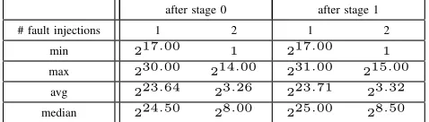
# fault injections 1 2 1 2
min 217.00 1 217.00 1
max 230.00 214.00 231.00 215.00
avg 223.64 23.26 223.71 23.32
median 224.50 28.00 225.00 28.50
to that, the evaluation of the equations Et has negligible
time complexity and hence is not considered further. The complexity for the RUF model is even higher with 224
evaluations. Under that model, the location of the fault injection is unknown and an attacker has to try all 16 possible combinations of the values of the variables ds and
et. This results in a complexity of aboutT ·220 (for RKF)
respectively T ·224 (for RUF) for stage 1 where T is the
number of key candidates fork0.
C. Experimental Results
The results of the Multi-Stage Fault Attack on LED-128 were obtained from 10,000 runs of the attack using the RUF model. Figure 3 shows the numbers of remaining key candidates after one and two fault injections for stage i ∈ {0,1}. The number of times a particular count of key candidates appeared during our experiments is displayed on the Y-axis. Table I shows the numbers of key candidates if 1 and 2 fault injections are performed in stage 0 and 1 of the attack. If the attacker injects just a single fault in stage0she has to execute, on average, 224·223.64= 247.64 evaluations
of single fault equations in stage1. Even in a rare best case where stage 0 yields217key candidates, the complete attack
requires241evaluations, which is still beyond feasibility. But
as soon as we inject a second fault in stage0, the number of key candidates fork0drops very rapidly to23.26. Thus, three
fault injections are required to break LED-128 on average: two in stage0 and one in stage1.
IV. APPLICATION TOPRINCE
As in the previous section we first describe the block cipher PRINCE, as specified in [5], and then show how to cryptanalyse it using the Multi-Stage Fault Attack algorithm from Section II. For the rest of the paper, let and ≫
denote a non-cyclic resp. cyclic shift of a bitstring to the right, and let⊕denote addition using bitwise XOR.
A. Specification of PRINCE
PRINCE is a 64-bit block cipher with a 128-bit key. Before an encryption (or decryption) is executed, a 64-bit subkey k2 is derived from the user supplied 128-bit key
k0k k1 viak2 = (k0≫1)⊕(k063). The subkeysk0
andk2 are used for input- and output-whitening. The core
of PRINCE is a 12-round block cipher which solely usesk1
as subkey. Figure 4 gives an overview of the cipher.
x
k0 k1 RC0
R1
k1 RC1
R2
k1 RC2
R3
k1 RC3
R4
k1 RC4
R5
k1 RC5
S M’ S-1 R-1 6
k1 RC6
R-1 7
k1 RC7
R-1 8
k1 RC8
R-1 9
k1 RC9
R-1 10
k1 RC10RC
11
k1k2 y
M S
RCik1
M-1S-1
RCj
k1
Figure 4. Layout of PRINCE.
Each round Ri and R−j1 with i ∈ {1, . . . ,5} and j ∈ {6, . . . ,10} consists of a key addition, an S-layer, a linear
layer which multiplies the state (represented by a64bit row vector) by a matrix, and the addition of a round constant (see Figure 4). The particular operations are described as follows.
1) S-Layer.: PRINCE uses the following 4-bit SBox:
x 0 1 2 3 4 5 6 7 8 9 A B C D E F
S[x] B F 3 2 A C 9 1 6 7 8 0 E 5 D 4
2) M-/M0-Layer.: The 64-bit state is multiplied by a64× 64 matrix M or M0. We refer to the original specification [5] for the exact definitions ofM andM0. It is important to observe that M0 is an involutive matrix andM =SR◦M0, whereSRis the ShiftRows operation as used in AES. Note that the multiplication by M is not an involution anymore, as ShiftRows is non-involutive.
3) RCi-add.: This operation adds the round constant
RCi to the state using bitwise XOR. The values of RCi
are defined in the table below.
i RCi
0–2 0000000000000000,13198a2e03707344,a4093822299f31d0, 3–5 082efa98ec4e6c89,452821e638d01377,be5466cf34e90c6c, 6–8 7ef84f78fd955cb1,85840851f1ac43aa,c882d32f25323c54, 9–11 64a51195e0e3610d,d3b5a399ca0c2399,c0ac29b7c97c50dd
Those constants have a special property: For all i ∈ {1, . . . ,10} the equality RCi ⊕ RC11−i =
c0ac29b7c97c50dd (= α) holds. Together with the fact that M0 is involutive, this makes it possible to perform encryption and decryption using basically the same circuit (or implementation) and is referred to as the α-reflection property. For details, see the specification of PRINCE [5].
B. A Multi-Stage Fault Attack on PRINCE
The fault attack on PRINCE requires two stages, as k0
can be easily derived as soon as k2 is known. As before
we now discuss the functionality of the Analyse method. To produce faulty ciphertexts for stage 0, we inject faults between the application of the S-Layer in round R−81 and
the multiplication with the matrix M0 in round R−1 9 . For
stage1, we inject faults exactly one round earlier. Figure 5 shows the fault propagation of a fault in PRINCE over two R−1 rounds.
In order to construct the fault equations used for key candidate filtering, we start, as in the case of LED, with the correct and faulty ciphertexts c = c0 k · · · k c15 and
c0 = c0
0 k · · · k c015 (or with the respective intermediate
states in the second stage) and work backward through the encryption, inverting each of the steps, up to the point before the application of the last SBox. This corresponds to the last “matrix” in Figure 5. Let us start by fixing notation.
Let i ∈ {0, . . . ,15}, and let vi and vi0 be variables
representing the i-th nibble of the correct and the faulty ciphertext (or the i-th correct and faulty state nibble in the case of the second stage of the attack) respectively. Moreover, the variablespirepresent key nibbles andqiround
constants. In stage 0 we substitute the nibbles ofRC11 for
qi and in stage 1 the nibbles ofRC10 for qi.
Let us point out a particular feature of the attack on PRINCE: an adversary cannot reconstruct one of the secret keys directly during stage0of the attack. The keysk1andk2
are applied immediately in succession during one run of the encryption, and thus we can only reconstruct the XOR value k1⊕k2. This fact presents no drawback for the feasibility of
the attack. In stage1we will directly reconstruct candidates for k1.
k1
RCi
SR-1 M’ S-1, k1
RCi+1
SR-1 M’ S-1, k1
RCi+2 r
f f ϕ(f)
0
ϕ(f)
1
ϕ(f)
2
ϕ(f)
3
r + 1
w
x
y
z
w
x
y
z
ϕ(w)
0
ϕ(w)
1
ϕ(w)
2
ϕ(w)
3
ϕ(x)
2
ϕ(x)
3
ϕ(x)
0
ϕ(x)
1
ϕ(y)
3
ϕ(y)
0
ϕ(y)
1
ϕ(y)
2
ϕ(z)
3
ϕ(z)
0
ϕ(z)
1
ϕ(z)
2
Figure 5. Fault propagation in PRINCE over twoR−1 rounds.
except for thej-th bitbj which is set to0. So, for example,
forj= 2, we getϕ2(a) =b0kb1k0kb3. Let w,x,y and
z be variables and letji∈ {0, . . . ,3}then we can describe
the fault equationsEi of PRINCE in the following way:
S(vi⊕pi⊕qi)⊕S(vi0⊕pi⊕qi) =
ϕji(w), i∈ {0, . . . ,3}
ϕji(x), i∈ {4, . . . ,7}
ϕji(y), i∈ {8, . . . ,11}
ϕji(z), i∈ {12, . . . ,15}
The values of the indices ji from the variables on the
right-hand sides of the equations Ei are derived from the
multiplication of the state with the matrixM0(see Figure 5) and depend on the location l of the injected fault. They assume the following values:
(j0, . . . , j15 ) =
(0,1,2,3,2,3,0,1,3,0,1,2,3,0,1,2),ifl∈ {0,7,10,13}
(3,0,1,2,1,2,3,0,2,3,0,1,2,3,0,1),ifl∈ {1,4,11,14}
(2,3,0,1,0,1,2,3,1,2,3,0,1,2,3,0),ifl∈ {2,5,8,15}
(1,2,3,0,3,0,1,2,0,1,2,3,0,1,2,3),ifl∈ {3,6,8,12}
(∗)
A 4-bit value t is called valid with respect to pattern
ϕji if the binary representation of t has a 0 at the bit
positionji. In the following we use bit pattern matching to
construct inductively a setSi which will ultimately contain
candidates for the nibble pi of the subkey. Key candidate
filtering is done in three steps: Evaluation, Inner Filtering
and Outer Filtering, which are described next. Note that the first two steps could be executed together, but for better comprehensibility we describe them separately.
1) Evaluation.: Each equation Ei is evaluated for all
possible 4-bit values u of nibble candidates associated to the variablepi. When the result of an evaluationt=Ei(u)
has been computed, the tuple (t, u) is appended to the set Si.
2) Inner Filtering.: In this step we check for all tuples (t, u) ∈ Si if the entry t is valid with respect to the bit
patternϕji. Those tuples that do not have a valid entrytare
discarded, all others are kept.
For example, we take fault equation E0 and assume that
a fault was injected in nibble l= 0. From the definition of ji above we see that the0-th entry ofj0is0. Moreover, we
assume that the tuple (t, u) = (0x7,0x3)is an element of S0and observe immediately that0x7matches the bit pattern
ϕj0= 0ks1ks2ks3. Thus(0x7,0x3)is a valid tuple and
0x3a potential candidate for the nibble associated top0. 3) Outer Filtering.: The idea in the final filtering step is to exploit the fact that the elements of the sets S4·m, . . . , S4·m+3 are related to each other for a fixed
m ∈ {0, . . . ,3}. This is due to the fact that the right-hand sides of the equations E4·m, . . . , E4·m+3 are derived
from a common pre-image. This can be utilized to build conditions for filtering candidates of the nibbles associated top4·m, . . . , p4·m+3. First we fixm∈ {0, . . . ,3}and order
the tuples (t4·m+n, u4·m+n) ∈ S4·m+n lexicographically
for all n ∈ {0, . . . ,3}. Then we compute the setsP4·m+n
containing the pre-images of all the valuest4·m+n. This is
done as follows. After the Inner Filtering, all valuest4·m+n
match the bit pattern derived from ϕ4·m+n. But we do not
know if thej4·m+n-th bit oft4·m+nhad value0or1before it
was fixed to0. Hence we obviously have two possible values for the pre-images of t4·m+n. One ist4·m+n itself, and the
other has a 1 at bit position j4·m+n. Then we intersect the
pre-image setsP4·m, . . . , P4·m+3with each other and obtain
a set Gm of pre-image candidates. After that we check for
each gm∈Gmif, for everyn∈ {0, . . . ,3}, there is at least
one tuple inS4·m+n which has the valueϕi4·m+n(gm)in its
first component. If so, gm is a valid pre-image. When all
pre-images have been processed, all tuples are deleted from the setsS4·m, . . . , S4·m+3, except those where the first entry
has a valid pre-image gm. This finishes the filtering stage.
Finally, after projecting the sets Si to their second
com-ponents ui, the Cartesian product over those projections is
computed to get the key candidates for k1 ⊕k2. If the
number of candidates fork1⊕k2is small enough, stage0of
the attack ends. Otherwise the procedure above is repeated as described in the Multi-Stage Fault Attack algorithm in Section II.
In the second stage of the attack, candidates for k1 are
computed using the previously described configurations for the fault injections. This is repeated until the number of candidates for k1 falls below the specified threshold value
τ1. As soon as this is the case, the candidates for k1 and
k1⊕k2are used to derive candidates for the subkeysk2and
k0. Finally, a brute-force search on the Cartesian product
K0×K1 is performed to find the actual keyk0kk1. 4) Complexity analysis of the attack.: The complexity of
theAnalysemethod in the case of PRINCE is very low. The
computationally most expensive part is the evaluation of the fault equations. For each of the 16 equations we have to compute 16 evaluations, since there are 16 possible values for the key nibbles. Altogether this results in 28 = 256
evaluations. As already mentioned in Section II, the number of evaluations is multiplied by a constant factor when using the RUF fault model. In the case of PRINCE, this factor has the value 4, as there are four different bit patterns for key candidate filtering and the attacker does know which pattern is the correct one, due to the unknown location of the fault injection. Therefore all four patternsji (see (∗)) have to be
tried, which gives 210 = 1024 evaluations for one run of
Analyse. In stage1the Analyse method may be executed
up to T times in the worst case, whereT is the number of k1⊕k2 candidates. This results in a complexity of about
28·T or 210·T evaluations, depending on the fault model
which has been used.
C. Experimental Results
0 10 20 30 40 50 Size of keyspace: 2n 1000
2000 3000 4000 5000
1 Fault 2 Faults 3 Faults 4 Faults
0 10 20 30 40 50 Size of keyspace: 2n 1000
2000 3000 4000 5000
1 Fault 2 Faults 3 Faults 4 Faults
Figure 6. Num. of candidates in stage 0 / 1 (left / right) for PRINCE.
sets between the fault models RKF and RUF were effectively non-existent. This can be explained by the observation that in almost all cases the candidate sets are empty when a wrong bit pattern(ji)i=0,...,15 is used for filtering. Figure 6
gives an overview (with stacked bars) on the two stages of the attack for multiple fault injections. Table II summarizes the results of the attack on PRINCE.
Table II
STATISTICS FOR THE NUMBER OF CANDIDATES OFk1⊕k2ANDk1.
after stage0 after stage1
# keys / # faults 1 2 3 4 1 2 3 4
min 217.00 1 1 1 216.00 1 1 1
max 250.00238.00224.00212.00 249.00244.00240.00243.00
avg 230.89211.44 24.12 21.47 230.41211.64 24.44 21.82
median 234.50219.50212.50 27.00 233.50221.50221.00221.00
For stage 0, we get on average 230.89 candidates when
injecting a single fault. This results in an overall complexity of 240.89 evaluations of single fault equations for stage 1
under the RUF model. This is not feasible on common hardware. But with a second fault injection in stage 0, the complexity drops to 211.44, which is easily doable. Thus,
on average, we need about two fault injections in stage 0 to be able to finish stage 1. Furthermore as expected the numbers for stage 0 do not differ significantly from those of stage1, except for the median, which surprisingly stays rather constant after the first fault injection. But as we only have to search through the generated key candidate sets, the average of 230.41 is feasible for brute-force. Nevertheless,
note that the maximal sizes of the key candidate sets are still quite high. Thus there might be cases where more than one fault injection is required for stage1. In summary, our experiments show that on average3to4faults are required to reconstruct the complete 128-bit key of PRINCE with a Multi-Stage Fault Attack on common hardware.
V. CONCLUSION
State-of-the-art ciphers increasingly employ keys that consist of independent subkeys. We introduced the generic concept of Multi-Stage Fault Attacks which target individual subkeys by multiple fault injections. One stage consists of several fault injections followed by mathematical analysis that yields a set of candidates for a subkey. We presented an algorithm that balances the number of fault injections allocated to different stages, in order to keep the sizes of final candidate sets sufficiently small for brute-force search. The generic algorithm estimates the expected effort for each stage and decides the number of fault injections to be performed based on user-specified threshold variables while taking interaction between subkeys into account. We illustrated the successful application of the general principle
on two recently introduced ciphers which we were able to break with 3 to 4 fault injections on average.
REFERENCES
[1] E. Biham and A. Shamir, Differential Cryptanalysis of DES-like Cryp-tosystems, In:CRYPTO1990, LNCS, vol.537, Springer, Heidelberg 1990, pp. 2–21.
[2] E. Biham and A. Shamir, Differential Fault Analysis of Secret Key Cryptosystems, In:CRYPTO1997, LNCS, vol.1294, Springer, Hei-delberg 1997, pp. 513–525.
[3] A. Bogdanov et al., PRESENT: An Ultra-Lightweight Block Cipher, In:CHES2007, LNCS, vol.4727, Springer, Heidelberg 2007, pp. 450– 466.
[4] D. Boneh et al., On the Importance of Elimination Errors in Crypto-graphic Computations, J. Cryptology14(2001), pp. 101–119. [5] J. Borghoff et al., PRINCE – A Low-Latency Block Cipher for
Pervasive Computing Applications, In:ASIACRYPT2012, LNCS, vol.
7658, Springer Heidelberg 2012, pp. 208–225.
[6] G. Piret and J.-J. Quisquater, A Differential Fault Attack Technique against SPN Structures, with Application to the AES and KHAZAD, In:CHES2003, LNCS, vol.2779, Springer, Heidelberg 2003, pp. 77– 88.
[7] J. Guo, T. Peyrin, A. Poschmann and M. Robshaw, The LED Block Cipher, In:CHES2011, LNCS, vol.6917, Springer, Heidelberg 2011, pp. 326–341.
[8] M. Hojsik and B. Rudolf, Differential Fault Analysis of Trivium, In:
FSE2008, LNCS, vol.5086, Springer, Heidelberg 2008, pp. 158–172.
[9] P. Jovanovic, M. Kreuzer and I. Polian, A Fault Attack on the LED Block Cipher, In:COSADE2012, LNCS, vol. 7275, Springer, Heidelberg 2012, pp. 120–134.
[10] L. Song and L. Hu, Differential Fault Attack on the PRINCE Block Cipher, InIACR Cryptology ePrint Archive, Report 2013/043, 2013. [11] M. Tunstall et al., Differential Fault Analysis of the Advanced
Encryption Standard Using a Single Fault, In:WISTP2011, LNCS, vol.6633, Springer, Heidelberg 2011, pp. 224–233.
APPENDIX
A. The functionsg0, . . . , g3 of the LED attack
Letcj,c0jandkjbe variables overF16, forj∈ {0, . . . ,15}, wherecj
andc0jrepresent nibbles of the correct and the faulty cipher state andkj
nibbles of the key. Furthermore letS−1denote the inverse SBox of LED.
Then we defineg0, . . . , g3 as:
g0 =S−1(C·(c0 +k0) +C·(c4 +k4) +D·(c8 +k8) +4·(c12 +c12)) +
S−1(C·(c0 +0 k0) +C·(c04 +k4) +D·(c08 +k8) +4·(c012 +k12))
g1 =S−1(3·(c3 +k3) +8·(c7 +k7 ) +4·(c11 +k11 ) +5·(c15 +k15)) + S−1(3·(c3 +0 k3) +8·(c07 +k7) +4·(c011 +k11 ) +5·(c015 +k15))
g2 =S−1(7·(c2 +k2) +6·(c6 +k6) +2·(c10 +k10 ) +E·(c14 +k14)) + S−1(7·(c2 +0 k2) +6·(c06 +k6) +2·(c010 +k10 ) +E·(c014 +k14))
g3 =S−1(D·(c1 +k1) +9·(c5 +k5) +9·(c9 +k9 ) +D·(c13 +k13)) +
S−1(D·(c1 +0 k1) +9·(c05 +k5) +9·(c09 +k9 ) +D·(c013 +k13))
B. The generalised key set fault equations E0(l),. . . ,E3(l) of the LED attack
Letu0, . . . , u3,w,x,yandzdenote variables overF16and letS−1
be the inverse SBox of LED. The second set of LED fault equations is then defined as
f0=(e0)−1·(S−1(u0) +S−1(u0+w)) f0=(e1)−1·(S−1(u1) +S−1(u1+x)) f0=(e2)−1·(S−1(u2) +S−1(u2+y)) f0=(e3)−1·(S−1(u3) +S−1(u3+z))
with valuese0, . . . , e3, which depend on the fault locationl, as written
below:
(e0, . . . , e3) =
(4,1,2,2),ifl∈ {0,1,2,3}
(8,6,5,6),ifl∈ {4,5,6,7}
(B,E,A,9),ifl∈ {8,9,10,11}