University of Windsor University of Windsor
Scholarship at UWindsor
Scholarship at UWindsor
Electronic Theses and Dissertations Theses, Dissertations, and Major Papers
10-5-2017
EXPERIMENTAL STUDY ON REHABILITATION OF CORRODED
EXPERIMENTAL STUDY ON REHABILITATION OF CORRODED
PIPES
PIPES
Sachith Jayasuriya
University of Windsor
Follow this and additional works at: https://scholar.uwindsor.ca/etd
Recommended Citation Recommended Citation
Jayasuriya, Sachith, "EXPERIMENTAL STUDY ON REHABILITATION OF CORRODED PIPES" (2017). Electronic Theses and Dissertations. 7267.
https://scholar.uwindsor.ca/etd/7267
This online database contains the full-text of PhD dissertations and Masters’ theses of University of Windsor students from 1954 forward. These documents are made available for personal study and research purposes only, in accordance with the Canadian Copyright Act and the Creative Commons license—CC BY-NC-ND (Attribution, Non-Commercial, No Derivative Works). Under this license, works must always be attributed to the copyright holder (original author), cannot be used for any commercial purposes, and may not be altered. Any other use would require the permission of the copyright holder. Students may inquire about withdrawing their dissertation and/or thesis from this database. For additional inquiries, please contact the repository administrator via email
EXPERIMENTAL STUDY ON REHABILITATION
OF CORRODED PIPES
By
Sachith Jayasuriya
A Thesis
Submitted to the Faculty of Graduate Studies
through the Department of Civil and Environmental Engineering in Partial Fulfillment of the Requirements for
the Degree of Master of Applied Science at the University of Windsor
Windsor, Ontario, Canada
2017
EXPERIMENTAL STUDY ON REHABILITATION
OF CORRODED PIPES
By
Sachith Jayasuriya
APPROVED BY:
______________________________________________ S. Chowdhury
Department of Electrical and Computer Engineering
______________________________________________ S. Cheng
Department of Civil and Environmental Engineering
______________________________________________ S. Das, Advisor
Department of Civil and Environmental Engineering
______________________________________________ T. Bolisetti, Co-advisor
Department of Civil and Environmental Engineering
iii
DECLARATION OF CO-AUTHORSHIP
I hereby declare that this thesis incorporates material that is result of joint research, as follows:
This thesis is a product of the joint research conducted in collaboration with Behrouz Chengi under the supervision of Dr. S. Das and Dr. T. Bolisetti. In all cases, the key ideas, primary contributions, experimental designs, data analysis, interpretation, and writing were performed by the author, and the contribution of co-author, Behrouz Chengi, was primarily through the advice and assistance in experimental testing.
I am aware of the University of Windsor Senate Policy on Authorship and I certify that I have properly acknowledged the contribution of other researchers to my thesis, and have obtained written permission from each of the co-author(s) to include the above material(s) in my thesis.
I certify that, with the above qualification, this thesis, and the research to which it refers, is the product of my own work.
I declare that, to the best of my knowledge, my thesis does not infringe upon anyone’s copyright nor violate any proprietary rights and that any ideas, techniques, quotations, or any other material from the work of other people included in my thesis, published or otherwise, are fully acknowledged in accordance with the standard referencing practices. Furthermore, to the extent that I have included copyrighted material that surpasses the bounds of fair dealing within the meaning of the Canada Copyright Act, I certify that I have obtained a written permission from the copyright owner(s) to include such material(s) in my thesis.
iv
ABSTRACT
Corrosion is a severe problem that affects oil and gas pipelines all over the world. When
combined with the complex loading combinations faced by buried pipelines, the effects
of corrosion can be devastating. Corrosion decreases the burst pressure, longitudinal
load-capacity, and lateral load-capacity of affected pipes. Much research has been
conducted to address this problem, and many repair techniques have been developed,
including the use of fibre-reinforced polymers (FRPs). Most of the research that has been
conducted on the use of FRP composites to repair pipes is concerned with increasing the
burst pressure. The purpose of this study is to use a relatively new fibre, basalt, to
increase the bending capacity of corroded pipes. To this end, five full-scale lab
experiments and finite element analysis was conducted. It was found that a composite
made of basalt fabric can increase the ultimate load of a pipe in bending. However, only a
pipe specimen with a corrosion depth of 20% of the wall thickness could fully recover the
bending capacity to that of an uncorroded pipe through the use of basalt FRP (BFRP)
composite. Analysis of different thicknesses of BFRP composites and different
orientations of the fabric using finite element analysis software indicated that increasing
v
ACKNOWLEDGEMENTS
I wish to express my sincere gratitude to Dr. Das and Dr. Bolisetti for providing me an
opportunity to do my master’s research under their supervision, as well as their guidance
and encouragement throughout this project. I would also like to thank the committee
members: Dr. Cheng and Dr. Chowdhury, for their thoughtful suggestions to improve this
thesis.
I am also grateful towards Matt St. Louis, Lucian Pop, Andy Jenner, my brother and my
friends Amirreza Bastani, Emad Booya, Behrouz Chegeni, Jothiarun Dhanapal, Hossein
Ghaednia, Eric Hughes, Navjot Singh and Jamshid Zohreh Heydariha who helped me
greatly in the lab. Without everyone’s assistance, this project would not have been
completed.
Finally, I would like to thank my family for the support and encouragement that they
vi
TABLE OF CONTENTS
DECLARATION OF CO-AUTHORSHIP ... iii
ABSTRACT ... iv
ACKNOWLEDGEMENTS ... v
LIST OF TABLES ... ix
LIST OF FIGURES ... x
LIST OF SYMBOLS ... xiii
LIST OF ABBREVIATIONS ... xvi
Chapter 1: Introduction
1.1 General ... 11.2 Fibre Reinforced Polymers ... 2
1.3 Fibres... 4
1.4 Resins ... 6
1.5 Objective ... 6
Chapter 2: Literature Review
2.1 Pipes Subjected to Bending ... 92.2 Corrosion in pipes ... 11
2.3 Effects of Corrosion ... 13
2.4 Traditional Repair Techniques ... 16
2.5 Composite Repair Systems ... 17
2.6 Codes and Standards ... 21
2.6.1 ASME B31G ... 21
2.6.2 ASME PCC-2... 25
vii
2.6.4 CSA Z662 ... 29
2.7 Summary ... 30
Chapter 3: Experimental Program
3.1 Instrumentation ... 373.2 Material Properties ... 39
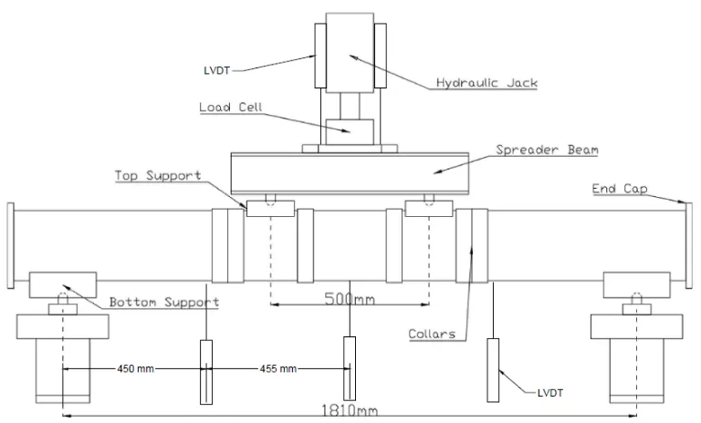
3.3 Test Setup... 40
3.4 Test Procedure ... 42
3.5 Corrosion Repair ... 43
3.6 Summary ... 44
Chapter 4: Experimental Results
4.1 Test 1 ... 524.2 Test 2 ... 55
4.3 Test 3 ... 57
4.4 Test 4 ... 59
4.5 Test 5 ... 61
4.6 Analytical Validation ... 63
4.7 Summary ... 67
Chapter 5: Finite Element Analysis
5.1 General ... 795.2 Model ... 80
5.2.1 Assembly... 80
5.2.2 Interaction ... 82
viii
5.2.4 Material Properties ... 83
5.2.5 Elements ... 85
5.3 Mesh Convergence Study ... 86
5.4 Validation of the model ... 88
5.5 FEA Models ... 88
5.6 Results ... 89
5.7 Summary ... 91
Chapter 6: Conclusions and Recommendations
... 100REFERENCES ... 102
ix
LIST OF TABLES
Chapter 3
Table 3.1: Test Matrix... 36
Chapter 4
Table 4.1: Experimental Results ... 53Table 4.2: Moment at yield for experimental tests ... 66
Table 4.3: Theoretical moment at yield ... 66
Chapter 5
Table 5.1: Elastic material properties of the pipe ... 83Table 5.2: Plastic material properties of the pipe ... 84
Table 5.3: Elastic material properties of the composite ... 85
Table 5.4: Effect of mesh density on the accuracy and duration of analysis ... 86
Table 5.5: Test matrix for the FEA simulation ... 89
x
LIST OF FIGURES
Chapter 1
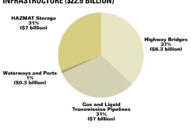
Figure 1.1: Annual cost of infrastructure in the U.S in 2002 ... 8
Figure 1.2: Mechanical properties of fibres ... 8
Chapter 2
Figure 2.1: Local buckling due to wrinkle in pressurized tube... 32Figure 2.2: Local buckling due to kink defect in unpressurized tube ... 32
Figure 2.3: Heavy duty clamps used for the repair of high integrity applications ... 33
Figure 2.4: Application of the wet lay-up system ... 33
Figure 2.5: Internal pressure vs. hoop strain curves for pipe specimens tested for burst pressure ... 34
Figure 2.6: Comparison of control specimen with corroded and CFRP-repaired specimens of 20% and 40% corrosion ... 34
Chapter 3
Figure 3.1: Specimen 2, with 1.2 mm (20% wall thickness) deep corrosion patch ... 45Figure 3.2: Steel coupon from pipe under uniaxial tension test ... 45
Figure 3.3: Rupture of steel coupon from pipe specimen ... 46
Figure 3.4: Testing of a BFRP coupon in shear ... 46
Figure 3.5: Ruptured BFRP coupon specimens after testing ... 47
Figure 3.6: Filling specimen 3 with water ... 47
Figure 3.7: Strain gages attached to the corrosion patch of specimen 2 ... 48
Figure 3.8: Schematic of the test setup ... 48
Figure 3.9: Test Setup ... 49
Figure 3.10: Initiation of wrinkle ... 49
Figure 3.11: Fully developed wrinkle ... 50
xi
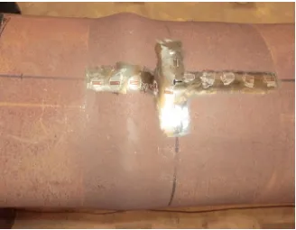
Figure 3.13: Specimen 3 after applying ten layers of basalt fabric and epoxy ... 51
Chapter 4
Figure 4.1: Location of strain gages for specimen 1 ... 69Figure 4.2: Location of strain gages for corroded specimens ... 69
Figure 4.3: Load-displacement curve of Specimen 1 ... 70
Figure 4.4: Strain behaviour at the wrinkle location of Specimen 1 ... 70
Figure 4.5: Comparison of load-deformation curves for Specimen 1 and Specimen 2 ... 71
Figure 4.6: Comparison of strain behaviour at the wrinkle location of Specimen 1 and Specimen 2 ... 71
Figure 4.7: Comparison of load-deformation behaviour of Specimen 3 with Specimen 1 and Specimen 2 ... 72
Figure 4.8: Comparison of strain behaviour at the wrinkle location of Specimen 1, Specimen 2 and Specimen 3 ... 72
Figure 4.9: Comparison of load-deformation behaviour of Specimen 4 with Specimen 1 and Specimen 2 ... 73
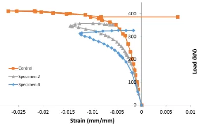
Figure 4.10: Comparison of strain behaviour at the wrinkle location of Specimen 1, Specimen 2 and Specimen 4 ... 73
Figure 4.11: Comparison of load-deformation behaviour of Specimen 5 with Specimen 1 and Specimen 4 ... 74
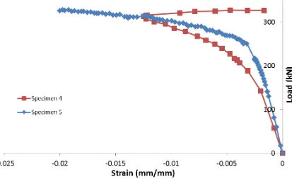
Figure 4.12: Comparison of strain behaviour at the wrinkle location of Specimen 5, Specimen 4 ... 74
Figure 4.13: Cross-section of the pipe specimen ... 75
Figure 4.14: Axial stress needed to cause yielding due to the hoop stress according to the von Mises yield criterion ... 75
Figure 4.15: Specimen 1 after testing ... 76
Figure 4.16: Specimen 2 after testing ... 76
Figure 4.17: Specimen 3 after testing ... 77
Figure 4.18: Specimen 4 after testing ... 77
xii
Figure 4.20: Engineering stress-strain curve of steel coupon ... 78
Chapter 5
Figure 5.1: Pipe specimen modeled using Abaqus software ... 93Figure 5.2: True stress-strain curve of the steel pipe ... 93
Figure 5.3: Higher mesh density at the middle ... 94
Figure 5.4: Pipe specimen with wrinkle defect after bending ... 94
Figure 5.5: Orientation of the BFRP fabric with ten layers oriented in the longitudinal direction and ten layers oriented in the circumferential direction ... 95
Figure 5.6: Plot of stress vs. mesh density ... 95
Figure 5.7: Comparison of load-displacement curves of Specimen 1 - experimental and simulated ... 96
Figure 5.8: Comparison of load-displacement curves of Specimen 2 - experimental and simulated ... 96
Figure 5.9: Comparison of load-displacement curves of Specimen 3 - experimental and simulated ... 97
Figure 5.10: Comparison of load-displacement curves of Specimen 4 - experimental and simulated ... 97
Figure 5.11: Comparison of load-displacement curves of Specimen 5 - experimental and simulated ... 98
Figure 5.12: Comparison of load-displacement curves of Specimen 5 with varying number of layers of BFRP attached longitudinally ... 98
xiii
LIST OF SYMBOLS
A Effective area of missing metal
A0 Original area
A1 A factor used to determine P’ (ASME B31G)
B A constant which depends on the corrosion depth (ASME B31G)
d Depth of corrosion
D Outer diameter of the pipe
D/t Diameter-to-thickness ratio of the pipe
D0 Outer Diameter of the pipe
E Young’s modulus
Ea Tensile modulus of the composite laminate in the axial direction
Eac √ (ASME PCC-2)
Ec Tensile modulus for the composite laminate in the circumferential direction
Es Tensile modulus for substrate material
f Service factor (ASME PCC-2)
F Design factor (CSA Z662)
F Design factor from ASMEB 31.4, ASME B31.8, ASME B31.11
Fa Sum of axial tensile loads due to pressure, bending, and axial thrust
Fax Applied axial load
Feq Equivalent axial load
Fsh Applied shear load
fT Temperature derating factor (ASME PCC-2)
L Location Factor (CSA Z662)
xiv
Ldefect Axial length of defect
Lover Overlap length of repair
Lrepair Axial length of repair
Ltaper Length of taper
M Stress magnification factor
Max Applied axial load
Mmax Buckling moment of the pipe
Mto Applied torsional moment
n The number of measurements taken for the Effective Area Method
P Internal design pressure
P’ Maximum pressure that is determined to be safe for the corroded section
Pb Burst pressure of the pipe
Plive Internal pressure within the pipe during the repair application
Ps Maximum allowable operating pressure
py Yield pressure
r Outer radius of the pipe
S Allowable stress of the substrate material
s SMYS
SF The estimated failure stress of the pipe
Sflow Flow stress
T Temperature factor (CSA Z662)
t Wall thickness of the pipe
Th Tensile strength of the composite in the hoop direction (CSA Z662)
tmin Minimum repair thickness
xv
ts Minimum remaining wall thickness of the pipe
w Design thickness of the fibre-reinforced composite (CSA Z662)
W Width of slot defect
z A factor used to calculate the stress magnification factor (ASME B31G)
γ Toughness parameter of the composite (ASME PCC-2)
εa Allowable axial strain of the laminate
εc Allowable circumferential strain of the laminate
νca Poisson’s ratio of the composite laminate in the circumferential direction
xvi
LIST OF ABBREVIATIONS
BFRP Basalt Fibre Reinforced Polymer
CFRP Carbon Fibre Reinforced Polymer
FRP Fibre Reinforced Polymer
GFRP Glass Fibre Reinforced Polymer
LVDT Linear Variable Differential Transformer
MAOP Maximum Allowable Operating Pressure
NPS Nominal Pipe Size
SMTS Specified Minimum Tensile Strength
1
Chapter 1
Introduction
1.1
General
A major problem facing the oil and gas industry is the corrosion of the pipelines that are
used to transport the products. Corrosion is the slow break down of a material through
chemical reactions. Corrosion affects not only pipelines, but other infrastructure such as
bridges, sewers, and water treatment facilities. A study was released in 2002 by CC
Technologies Laboratories, Inc. with support from the FHWA (Federal Highway
Administration) and NACE International which provides a very comprehensive look at
the impact of corrosion on America’s economy. The objective of the study was to
determine the impacts of corrosion on the economy and find cost-effective strategies to
manage corrosion.
The study states that the estimated annual cost of metallic corrosion in the U.S. is $137.9
billion, which when extrapolated to the total U.S. economy totals to $276 billion, 3.1% of
the U.S. Gross Domestic Product as of 1998(NACE International, 2002). One of the
biggest contributors to this substantial cost is water and wastewater distribution systems
($36 billion) that need to be replaced or are in need of corrosion inhibitors. The World
Corrosion Organization estimates that globally US$2.2 trillion is used to combat
corrosion (Hays, n.d.). The repair of corroded pipelines as well as the catastrophic
damage caused by the pipe failures cost billions of dollars each year to the economy.
According to the report by CC Technologies, the cost of corrosion in the gas and liquid
2
Traditionally corrosion defects would be repaired with a steel sleeve enveloping the
corroded area or by cutting and replacing the corroded section entirely. While these
techniques are effective, they take a lot of time to complete, can be very costly and the
use of hot-work near the volatile substances inside the pipe can be very dangerous.
1.2
Fibre Reinforced Polymers
In recent years many pipeline operators have opted to use FRP (Fibre Reinforced
Polymer) repair techniques to restore the original strength of corroded pipes. Repairing
pipelines using FRP materials is more attractive than using steel because of the ease of
installation and often times can be done at a fraction of the cost of steel repair.
According to an article published in the November 2002 issue of Pipeline & Gas Journal
by Jim Cuthill, carbon composite repairs can be used to withstand through-wall defects at
the time of the repair or any time in the future, during the design life of the repair(Cuthill,
2002). He also went on to say that in some circumstances, the original substrate of entire
pipe sections can be allowed to be subjected to complete corrosion without the loss of
pipeline strength or pressure integrity. FRP composites have been used in many
small-scale and large small-scale applications around the world. As stated by Jim Cuthill on the
Pipeline & Gas Journal, more than three metric tons of carbon fibre and three metric tons
of resin were used to make a 75-m long repair on a 60-inch steel saltwater feed line with
extensive corrosion. The project, completed by FD Alliance (a partnership formed
between DML Composites and Furmanite International), was completed at approximately
35-40% of the cost of replacement. CFRP composites have been used in the repair of gas
lines operating at exceptionally high pressures and temperatures, such as a carbon steel
3
deteriorating from external corrosion. The repair was completed by FD Alliance while
the plant was live, and the pipeline was operating at 124oC and 1160 psig.
A partner of the Natural Gas STAR program (a program intended to help reduce methane
emissions) has reported saving over 106 million cubic feet of natural gas by choosing
composite wrap as an alternative to pipeline replacement between 1993 and 1999. Use of
composite wrap on gas pipelines as an alternative to older methods of repair can reduce
safety risks, decrease pipeline downtime as pipeline repair is possible with shutting down
gas flow, save gas for sale since purging of the pipeline is not required, and decrease
methane emissions to the atmosphere because cutting into the pipe is not required. In
some circumstances when the use of composites may not be the most economical option,
which may be the case for long defects, some still prefer composite wrap over pipeline
replacement. In such cases, factors such as urgency and speed of repair or lack of a
back-up gas sback-upply may outweigh the cost of repair and influence the project manager to select
composite wrap systems due to their faster repairs. Composite wrap repair eliminates the
need for special equipment or skilled labourers such as welders. In a case reported by a
Natural Gas STAR partner, a 20-inch defect on a pipe was repaired using composite wrap
sleeves in four hours by two trained workers, with the entire process – from excavation to
reburial - taking only two days. Since the pipe was near a creek bed, it was beneficial to
not cut the pipeline as that would expose the water in the creek to the material being
transported in the pipe.
FRP composites are made of reinforcing fibre that is impregnated with resin. In a
composite the fibres provide the strength and stiffness while the resin holds the fibres in
4
elastic modulus, high ultimate strength and sufficient elongation at fracture. The three
most common types of fibres are carbon, glass and aramid.
1.3
Fibres
Carbon fibres have a lengthy manufacturing process which includes oxidation,
carbonization and graphitization. Graphitization helps increase the elastic modulus of the
fibres since graphite has a higher tensile modulus than carbon. The end result has high
tensile strength and stiffness while being highly resistant to aggressive environments.
However, carbon fibres have a very low elongation at failure with ultimate tensile strain
varying between 0.5 and 1.1% (Burgoyne et al., 2007). The biggest drawback of carbon
fibres is the cost, which is a result of the high price of the raw materials and the long
process of carbonization and graphitization.
Glass fibre is made of silica, soda ash, lime and several other materials that is melted and
drawn into continuous threads. Different additives are used during the fabrication process
to improve the fibre’s ability to become saturated by resin, improve the fibre’s flexibility,
and improve the strength of the bond. E-glass, the most common type of glass fibre, is
used in a wide range of applications. However, in terms of tensile strength, ultimate
tensile strain and Young’s modulus it is inferior to the more expensive S-glass (Figure
1.2).
The term ―aramid‖ is a combination of the words aromatic polyamide, which are fibres
with the molecule chains aligned along the axis of the fibre. Due to the strength of this
chemical bond aramid fibres are able to demonstrate high strength and stiffness. There
5
Technora, SVM, and Twaron, among others. Twaron fibres are manufactured by spinning
a liquid crystalline solution of PPTA polymer (p-phenylene terephthalamides) in
concentrated sulfuric acid and extruding the solution through spinning holes. The specific
method of production varies for each product. Consequently, the mechanical properties of
aramid products vary between carbon fibres and glass fibres.
A relatively new fibre being studied for use in structural reinforcement is basalt. Even
though the idea to extract fibres from basalt was first introduced in 1923 by Paul Dhè,
compared to carbon and glass, not much research has been done on reinforcement
abilities of basalt composites. Lately basalt fibres have been gaining a lot of interest due
to its eco-friendly composition and relatively low cost.
Basalt Fibre Reinforced Polymers (BFRPs) are cost effective because the raw material
used to make BFRP is basalt rock, the most abundant igneous rock on Earth. There are
major basalt quarries concentrated in Russia, Georgia, Ukraine, China and eastern areas
of the U.S.A making the raw material is easy to obtain. However, unlike glass which
transmits infrared energy, basalt absorbs infrared energy forcing the manufacturers to
hold the basalt rocks in the reservoir for an extended period of time in order for the
melting basalt to be heated uniformly. As a result the cost of basalt fibres is higher than
E-glass, but lower than S-glass and much lower than carbon fibres while the mechanical
properties are comparable to S-glass. As the manufacturing of basalt fibres increases, the
price of BFRP is expected to decrease.
The environmentally-friendly nature of basalt is due to the fact that the fibres are made
6
the melting process. As a result, no industrial waste is released during production and
since basalt is inert, there is no toxic reaction with water or air.
1.4
Resins
Thermoset resins, as the name indicates are set when exposed to heat. Prior to curing the
resin would be in a liquid state, then heat would be introduced, usually through a
chemical reaction. Once cured the resin and the fibres that form the composite laminate
become very rigid. This process cannot be reversed and the shape of the composite
cannot be changed without chemically breaking down the resin-matrix. Some common
types of resins include polyester, vinylester, polyutherene, silicone and epoxy. While
epoxy tends to be the most costly resin, it offers relatively high mechanical properties.
Unlike thermoset resins, thermoplastic resins are solid in their natural state. When heated
thermoplastic resins become soft or fluid. Since thermoplastic resins behave as a solid in
its natural state, it is considerably harder to use them to impregnate the reinforcing fibres.
The resin must first be melted so that it is fluid, then pressure is used to saturate the
reinforcing fibres with the resin. When cooled down to room temperature under the same
pressure, the composite becomes solid. While the process of manufacturing reinforcing
composites using thermoplastic resins is harder, they offer a major advantage in their
ability to change shape. When thermoplastic composites are heated their shape can be
bent to have a curvature.
1.5
Objective
The objective of this research is to examine the effectiveness of basalt FRP (BFRP)
7
earthquakes, landslides, soil upheaval or snaking lead to the bending of pipelines. As the
pipeline bends small ripples that are formed on the pipe localize into one or more large
wrinkle depending on the curvature of the bend. If there is corrosion in a pipeline situated
in areas with a lot of soil movement, or frost upheaval, the process would be accelerated.
In order to alleviate the axial stress due to internal pressure or temperature fluctuations,
the pipe will deform laterally in the corroded area (snaking) leading to wrinkling.
This research will be used to determine whether an FRP composite made of basalt fibre is
able to restore the load carrying capacity of a corroded pipe to its original state and also
whether it can change the buckling mode and stop the wrinkling process of a corroded
8
Figure 1.2: Mechanical properties of fibres (Burgoyne et. al, 2007)
9
Chapter 2
Literature Review
This literature review aims to summarize the information the author has found in the
literature regarding bending of pipes, effects of corrosion, traditional repair techniques of
pipes and the emerging composite repair techniques, as well as the current codes and
standards that provide guidelines on pipeline repair.
2.1
Pipes Subjected to Bending
There have been a various studies conducted on the local buckling behaviour of tubes
subjected to bending.
Ju and Kyriakides (1991) used unpressurized tubes of varying diameter-to-wall thickness
(D/t) ratios to study the behaviour of cylindrical shells under bending. The study found
that the tube cross-section initially shows uniform ovalization under bending. Then the
tube buckles on the side subjected to compression and forms ripples. The study
concluded that the limit load for buckling occurs at a curvature that is significantly lower
than would be expected. The moment drops steeply after reaching the limit load. As the
bending increases, the shell buckles further, as the ripple with the most severe
deformation develops a sharp diamond-shaped kink.
Limam et. al (2010) studied the behaviour of pressurized tubes under bending. Similar to
Ju and Kyriakides (1991), this study also found that the tube cross-section initially shows
ovalization when bending. However, internal pressure helps reduce ovalization and
causes the pipe to expand. The tube buckles on the compressive side under bending and
forms wrinkles (Figure 2.1). As the bending increases, the amplitude of the wrinkles
10
deformation and buckling localizes around this wrinkle. The work done by Ju and
Kyriakides (1991) and Liamam et. al (2010) show that the presence of internal pressure is
the cause of wrinkle formation in pipes subjected to bending since unpressurised pipes
will fail with the development of an inwards kink (Figure 2.2).
Liamam et. al (2010) observed that the internal pressure can considerably delay
localization and collapse of a pipe subjected to bending, noting that a pipe pressurized to
75% of yield pressure was able to withstand a collapse curvature at the point of collapse
that is six times as much as the same pipe that was unpressurized. However, in order to
realize this benefit of internal pressure, the pipe must be sufficiently ductile in order to
avoid failure of the material before developing the bulge.
The findings by Limam et. al (2010) confirm the conclusions published by
Yoosef-Ghodsi et. al (2000) that a buried pipeline that is deformed in axial compression or
bending beyond its maximum capacity will form a wrinkle shaped defect. Yoosef-Ghodsi
also stated that a pipe with a wrinkle defect can deform well into the post-wrinkling
phase without rupturing.
Yudo and Yoshikawa (2015) analyzed the buckling strength of straight and curved pipes
with varying lengths, diameters, thicknesses, and radius of curvatures of pipes using FE
software. It was found that the buckling strength of the pipe is reduced due to the
cross-sectional ovalization that occurs during the bending of the pipe. Since the ovalization is
highest at the center, the buckling is limited to the compressive side of the midspan.
11
deformation of the pipe grows larger. Yudo and Yoshikawa proposed an equation to
calculate the buckling moment for long pipes as
(2.1)
However, it is important to note that this equation does not take internal pressure into
account.
2.2
Corrosion in pipes
Pipeline corrosion occurs due to a pipeline’s interaction with its surroundings. In an
article published by Prabhu (2016), the author states that most pipeline corrosion occurs
due to an electrochemical reaction, where electrons from the surface of the pipe are
transferred to nearby oxygen atoms, acids or cations of different metals. An electrolyte
such as water must be present for the transfer of electrons to occur. As stated by Prabhu,
there are internal and external factors affecting the corrosion rate of a pipeline. External
factors consist of the surrounding environment of the pipe, such as the soil chemistry and
moisture for buried pipelines and water chemistry for submerged pipelines. Internal
factors affecting the corrosion rate include the properties of the gasses and liquids being
carried, such as the oxygen content and reactivity levels, as well as the operating
parameters of the pipeline: the temperature, flow rate and pressure. The interaction of
dissimilar metals within the piping system can also lead to galvanic corrosion.
Prabhu outlined the following different types of common pipeline corrosion:
Uniform Pipe Corrosion: thinning of the pipe caused by uniform loss of material
12
Pitting Corrosion: small cavities on a pipe surface caused localized deterioration
due to material defects or an aggressive chemical.
Selective Leaching (dealloying): corrosion of a solid alloy due to loss of an
element that forms the alloy, through reactions with chemical substances that are in
contact with the surface.
Galvanic Corrosion: deterioration caused by coupling of dissimilar metals with an
electrolyte (water, salt water). The metal more susceptible to corrosion becomes the
anode and corrodes faster than it would by itself, while the other, metal becomes the
cathode and corrodes slower than it would by itself. (Cathode is the negatively charged
electrode, attracts positive charge (cations) and is the electron donor. Anode is the
positively charged electrode, and it attracts electrons, is the source of positive charge in
the coupling.)
Crevice Corrosion: occurs in tight joints and crevices where the fluids may have
become stagnant. The concentration of oxygen becomes lower than the surrounding
water due to the crevice geometry which makes access into the crevice difficult. The
corrosion now becomes an electrochemical reaction where the surface of the crevice is
the anode. The anodic surface provides electrons to satisfy the reaction which in turn
produces metal ions that hydrolyze and give off protons and forming corrosion products.
The release of protons gives the crevice a strong positive charge that attracts negative
ions in the environment, such as chlorides and sulfates. This leads the crevice to become
more and more acidic, with pH levels sometimes equivalent to pure acids.
Stray current Corrosion: is a chemical reaction driven by electricity from stray
13
reactions that occur in this process is similar to galvanic corrosion which produces
current internally. However, since the external stray current is much higher than that
possible by galvanic cells, the corrosion damage will be much higher as it is proportional
to the strength of the passing stray current. Stray current corrosion occurs at the location
where the current leaves the pipe. Once a stray current enters the pipeline, it may travel
for some distance, seeking the path of least resistance. When the current leaves the
pipeline, the location where the current leaves the pipeline will be left with localized pits
and cavities.
2.3
Effects of Corrosion
When a pipe is subjected to corrosion, the load-carrying capacity of the pipe decreases as
the corrosion slowly reduces the thickness of the pipe. Due to changes in temperature,
either in the pipe’s surroundings or the fluid that is carried inside the pipe, the pipe will
expand or contract, creating axial stresses in the pipe walls. Also, ground movement,
gradual or abrupt, can also create similar axial stresses. However, movements of the soil
such as those caused by landslides, are more likely to act as transverse loads and subject
the pipe to longitudinal bending. Many studies have been conducted to study the effect of
corrosion on a pipe’s axial and transverse load carrying capacity (Dewanbabee et. al,
2013) (Cosham and Hopkins, 2005).
The effect of corrosion on the performance of pipelines was studied by Dewanbabee et. al
(2013) using ten full-scale lab tests and an FEA parametric study. The research was
undertaken to study how corrosion affects the strength of pipes subjected to axial
compression and internal pressure. This study consisted of eight lab tests with varying
14
rectangular), and varying pressure (0.2py, 0.4py) and two tests on control specimen with
varying pressure (0.2py, 0.4py). The study observed that increased corrosion depth
reduces the net axial load capacity. It was found that not only the depth, but the shape of
the corrosion also affects the performance of the pipe; Dewanbabee et. al (2010)
concluded that increasing the corrosion in the direction of the circumference of the pipe
reduces the net axial load capacity.
Elchalakani (2016) conducted 3-point bending test on circular hollow sections with
varying corrosion depths and varying lengths of corrosion. The study found that
increasing corrosion length along the longitudinal direction, significantly decreases the
ultimate lateral load capacity.
Cosham and Hopkins (2005) developed a set of guide lines for assessing corrosion
defects in pipelines, that can be used to assess pipeline defects. As summarized by
Cosham and Hopkins, the longitudinal length of corrosion is much more important in
controlling the burst strength of a pipe than the circumferential length under internal
pressure loading. However, when axial or bending loads are introduced, the
circumferential length must also be considered to determine the burst pressure. The study
also found that defects that are short in length, typically less than three times the
thickness of the pipe, does not reduce the burst pressure below the yield pressure of the
uncorroded pipe.
The methods that can be used to prevent or control corrosion depend on various factors
which include, among others, the specific material to be protected, what it comes into
15
(saltwater, industrial). Common methods of controlling corrosion involve protective
coatings, corrosion resistant alloys, substituting metals with fibres and polymers,
corrosion inhibitors, and cathodic protection (Prabhu, 2016).
Cathodic protection is a process in which a sacrificial anode is connected to the surface to
be protected, creating an electrochemical cell where the surface being protected is the
cathode. When in the presence of galvanic corrosion the sacrificial anode will corrode
instead of the metal surface to which it is connected. This protection typically lasts 15-25
years (Peterborough Utilities Group).
The reduced load-carrying capacity of the pipelines due to corrosion can be very
dangerous. Reduced wall thickness in sections of the pipeline can lead the pipe to burst
from the internal pressure. Also, excessive deformation of those regions could cause a
rupture in the pipe, leading to oil spills or natural gas leaks.
Natural gas, when leaked, is a contributor to global warming as it is made up of mostly
methane. While natural gas does not present an immediate health and safety threat, the
respiratory conditions of those exposed to gas leaks may be aggravated. On the other
hand, an oil spill has much more dire effects on the environment, and the health and
safety of nearby animals and humans. A leak in an oil pipeline causes pollution in the
nearby area including land damage, water poisoning, and destruction of habitats.
Exposure to the leaked oil could be fatal for animals; if the leak occurs underwater, fish
and birds that prey on the fish will be highly susceptible. A leak in a pipeline will be very
damaging to the owners of the pipeline as well, due to the loss of oil or gas, cost of the
16
take great care to repair or replace a pipeline before a leak can occur. Over the years
many repair techniques have been developed to repair damaged sections of a pipe.
2.4
Traditional Repair Techniques
AEA Technology Consulting (2001) has prepared a report with guidelines for temporary
and permanent pipe repair for England’s Health and Safety Executive. The document
covers a range of repair options applicable for the repair of most common types of pipe
deterioration. The guide focuses mainly on metallic repair options such as clamps;
however, a review of the use of composite materials for pipe repair has also been
included.
The most basic method of pipeline repair consists of welding a curved, metallic patch
over a small defect. This repair option is not suitable for high integrity applications. The
patch clamp, a similar technique, uses a metallic clamp that is bolted closed
longitudinally, with an elastomeric seal used to secure the damaged area. If the external
surface of the pipe is damaged to an extent where the elastomeric seal cannot achieve
proper contact, filler material may need to be used to restore the original geometry of the
pipe surface. A similar device, the pin-hole repair clamp is a specialized tool that can be
used to repair pin hole leaks found in pipes.
For higher-integrity applications, medium- duty and heavy-duty repair clamps may be
used. Heavy-duty clamps used to secure high-pressure pipes consist of two cylindrical
half shells that will be bolted around the pipe (Figure 2.3). Medium-duty clamps used for
low pressure applications may be made as a single piece, with a flexible region, allowing
17
defective area with elastomeric seals at the inside face of the clamps. As the clamps are
tightened, the compression forces may allow for a tighter seal.
Similar to bolted clamps, encircling sleeves consisting of two cylindrical halves that
conform to the geometry of the pipe when welded together longitudinally is a simple
method to reinforce a defective section of a pipe. For pressure applications, the encircling
sleeves must be fully seal-welded to the pipe.
A more advanced version of the encircling sleeves consists of using split-sleeves with
epoxy-grout in the middle. This method allows for the use of a fast curing polyester based
resin seal to affix the sleeve onto the pipe instead of sealing through welding. This repair
method is still capable of withstanding high circumferential and axial stresses;
furthermore, it is capable of withstanding on-going internal metal loss even if the extent
of the corrosion advances through the pipe wall. The epoxy grout transfers the stresses
from the pipe substrate to the steel repair sleeve, thereby confining the steel pipe and
preventing the damaged area from radially expanding outward. The use of epoxy grout
introduces limitations such as operating pressure which is limited to approximately 1450
psi and temperature which ranges between 3oC and 100oC. This is not a rapid repair
method as the two cylindrical sleeve-halves are required to be welded together, and the
epoxy needs approximately 24 hours to cure to 90% of its ultimate strength (AEA
Technology Consulting, 2001).
2.5
Composite Repair Systems
While conventional steel repair techniques have been effective, recently composite repair
18
clamps as they are not constrained by length or complex geometry; and when compared
to welding, since no hot work is required composite repairs are safe even when applied
while the pipeline is operational. Other benefits of fibre composites include their
manoeuvrability, ease of use in tight spaces and low density, allowing FRP (Fibre
Reinforce Polymer) repairs to restore structural strength without significantly increasing
the self-weight of the structure. Pipeline repair using FRP began in the late 1980s. After
continuous development of FRP composite systems, there are now a few different options
available in the market for pipe repair using composite FRP systems. FRP composites can
be categorized as cured layered systems, flexible wet lay-up systems, and
pre-impregnated systems (Lim et. al , 2015).
Flexible Wet Lay-up systems use a fabric FRP that is flexible before curing. In order to
apply this repair technique, voids and corroded areas are cleaned and filled in with putty.
Then an epoxy resin is applied on the pipe substrate and the FRP fabric is wrapped
around the pipeline while the fabric is also coated with the epoxy resin (Figure 2.4). After
curing, the wrap becomes extremely rigid. This method has an advantage over using steel
repair techniques because it can be applied on bends and joints. However, as stated by
Lim et al. (2015) there could be problems with the in-situ curing process when done in
the field, due to high ground water table. Also the application of this system may be
difficult in confined spaces.
Pre-cured layered systems are factory-manufactured with layers of FRP composites
bonded together with a strong adhesive. It coils as cured in order to fit a pipe’s geometry.
Since it is pre-manufactured, better quality control can be expected than the wet lay-up
19
bends and joints. Similar to the wet lay-up system, during application, the corroded area
is filled with infill material and the pre-cured FRP composites are attached to the pipe
using adhesive (Lim et al., 2015).
The pre-impregnated system is a mix of the wet lay-up and pre-cured systems as fibres
are coated with a matrix material (epoxy) and partially cured in a controlled, factory
setting. Since the fibres are only partially cured they are still flexible at the time of
application. However, they need to be stored in a cold environment to prevent full curing.
ProAssure Wrap Extreme, a pre-impregnated composite repair system, is suitable for
both onshore and offshore applications. It is made of E-glass fibre with an epoxy that is
capable of curing underwater with minimal loss of adhesion and mechanical properties
(Lim et al., 2015).
In order to validate the effectiveness of composite repair systems many researchers have
conducted experimental work involving pipes with simulated corrosion. Chan et. al
(2014) used a pre-cured layered system to repair a corroded section of pipe. An API 5L
X52 pipe was machined to reduce the wall thickness by 50% to simulate corrosion. The
length of the corrosion patch was 622 mm in the axial direction and covers the full
circumference. The purpose of the investigation was to see if the burst pressure of the
machined pipe could be increased with the use of Helicoid Epoxy Sleeve (HES)
composite repair system. The HES system uses carbon fibre for reinforcement with
epoxy grout being used as the fill material. Burst pressure of the pipe was calculated
according to American Bureau of Shipping standard, a guide for building and classing
20
( ) (
) (2.2)
The thickness of the laminate needed for repair is based on the ASME PCC-2, Short-term
Pipe Spool Survival Test (Appendix III) guidelines. Two layers of 0.8mm thick carbon
FRP strips were used to satisfy repair thickness of 1.08 mm.
It was found through numerical analysis that the use of the HES system increased the
burst strength of the corroded pipe by 124% at the design pressure (Figure 2.5). The
experimental results and FEA analysis confirmed an increase in the burst strength of the
corroded pipe beyond that of the uncorroded pipe (Chan et al., 2014).
M. Elchalakani (2016) conducted 3-point bending tests on steel tubes to investigate the
bending behaviour of circular hollow sections, both corroded and repaired using carbon
FRP (CFRP) fabric. The corrosion in the CHS was simulated by machining 20%, 40%,
60%, and 80% off of the wall thickness over the entire circumference. No internal
pressure was applied on the CHS for the tests. Two types of composite wraps were used
for the repair: Structural Technology V-Wrap C200 and Sika-Wrap 300-C. 31 specimens
with a diameter of 101.6 mm and thickness of 5.0 mm were tested. The study found that
all the repaired CHS saw a large increase in strength, with a maximum of 282% for one
of the 80% corroded specimen. The average increase in strength of the corroded CHS
was 97%. However, none of the specimens were able to revert back to the original,
uncorroded strength, except for the 20 % corrosion specimen with two layers of wrap
(Figure 2.6).
Shouman and Taheri (2009) conducted FEM analysis on corroded pipe sections subjected
21
wrap system, which uses E-glass, was modelled around a defect of 80% of the wall
thickness. It was found that a corroded pipe that has been retrofitted with the Clock
Spring composite wrap can outperform the virgin pipe section.
2.6
Codes and Standards
As more research is being conducted on the use of FRP systems to repair corroded pipes,
many codes and standards have adopted guidelines to assess the remaining strength of the
corroded pipe sections and repair them.
2.6.1 ASME B31G
A popular guideline used to measure the remaining strength of corroded pipes is the
ASME B31G manual. In the 1991 version of the ASME B31G manual, the depth of a
corrosion pit is calculated as relative to the nominal uncorroded wall thickness as a
percent: . The maximum allowable longitudinal length of the
corroded area is determined by the equation:
√ . (2.3)
The value of the constant B is determined by:
√(
5) (2.4)
In the above equation the value of B must not exceed 4, unless the corrosion depth is
22
corrosion depth of 10-80% of the nominal wall thickness should not have a corrosion
patch longer than L, calculated in Equation 2.3.
Based on the above equations, a few tables have been formed in the ASME B31G
standard that allows the reader to quickly establish an estimate of the maximum corrosion
length, depending on the diameter, wall thickness and maximum corrosion depth of the
pipe.
If the length of corrosion is greater than the calculated value of L, and the depth of
corrosion is 10 - 80% of the wall thickness, the ASME B31G recommends repairing the
corroded section or lowering the maximum allowable operating pressure (MAOP) to P’
or below, where P’ is the maximum pressure that is determined to be safe for the
corroded section.
The value of P’ depends on the factor A1, which compares the length of longitudinal
corrosion to the pipe’s diameter and thickness:
( ⁄√ ) (2.5)
If A1 is less than or equal to 4, P’ is calculated as:
(2.6)
Where P is the greater of either the MAOP or . F is a design factor from ASME
B31.4, ASME B31.8, ASME B31.11. The value of F is normally taken as 0.72 (Pipelines
and Risers, 2001). If A1 is greater than 4, P’ is calculated as :
𝑃′ 𝑃 - ( 𝑑
𝑡 )
23
′
* + (2.7)
The ASME B31G document has gone through heavy revisions since the first issue in
1984, in order to incorporate other, newer methods of corrosion evaluation that have been
proven reliable. Depending on the data available and the data needed, the 2009 revision
of the document provides four levels of analysis to evaluate the conditions of the pipe,
ranging from Level 0 to Level 3. A Level 0 evaluation is the most basic level of analysis,
where the diameter and thickness of the pipe is used with the maximum depth of
corrosion to find the maximum allowable length of corrosion or vice versa from a set of
tables. If the actual length of corrosion on the pipe is lower than the table, the metal loss
area is deemed acceptable. Level 1 evaluation is used to determine whether the operating
pressure of the pipe is acceptable with the given metal loss area. The estimated failure
stress level of the pipe, S F, is mainly dependent upon the bulging stress magnification
factor, M, and flow stress, S flow. As stated in the code, ―flow stress is not a property
specified in a material grade or finished product standard‖. Instead, the code provides
three equations to define the flow stress, based on the operating temperature and SMYS
in paragraph 1.7(b).
(2.8)
when operating temperature is below 250oF
( ) (2.9)
24
In the 2009 version of the ASME B31G code, the bulging stress magnification factor, M,
is defined as:
( - ) (2.10)
for , and
(2.11)
for , where
t (2.12)
Using the provided bulging stress magnification factor, the estimated failure stress level
of the pipe, SF, can be determined using the equation:
(2.13)
If the failure stress is greater than the hoop stress multiplied by an acceptable factor
of safety, the flaw is deemed acceptable. It is important to note that this standard does not
consider the effect of axial stresses on pipe defects.
Level 2 evaluation is also used to determine the failure stress of the pipeline; however, it
is performed using the Effective Area Method. In this case the approximation of the
defect area has been changed when calculating the failure stress, SF:
(2.14)
𝑆𝐹 𝑆𝑓𝑙𝑜𝑤*
(𝑑 𝑡⁄ ) (𝑑 𝑡⁄ ) 𝑀+
25
t v r ss t
r r
Several measurements need to be taken along the metal loss area in order to use the
Effective Area Method as it needs a detailed profile of the corrosion along the
longitudinal direction of the pipe. This is an iterative method that examines all possible
combinations of local metal loss with respect to the original material. The number of
iterations is determined by:
( ) ⁄ (2.15)
u r sur ts t
A Level 3 evaluation is the most complex of the four as it involves finite element
modelling of the corroded region. In order to get an accurate result, the loadings,
boundary conditions, ovality, material properties of the pipe, along with many other
factors affecting the pipe have to be modelled correctly. However, since the model is
made specifically for the pipe, the results will be more accurate than the previous three
methods.
2.6.2 ASME PCC-2
ASME PCC-2 is a standard that provides guidance on the matter of repairing pressure
equipment and piping. Once the pressure equipment has been properly inspected and it is
determined that repairs are necessary, the technical procedures and information provided
26
in the standard cover methods involving metal deposits, such as welding or soldering,
methods involving mechanical repairs including bolted clamps, and methods involving
non-metallic composite repair systems.
For composite repairs, the standard considers two design cases: Type A, where the pipe
does not leak and only needs structural reinforcement and Type B, where the pipe needs
structural reinforcement and sealing of leak.
For pipe systems, where the underlying substrate does not yield, the minimum thickness
needed to support the hoop stress due to internal pressure is calculated by:
( ) ( ) (2.16)
For pipe systems, where the underlying substrate does not yield, the minimum thickness
needed to support the axial stresses due to bending or other axial loads is calculated by:
( ) (
) (2.17)
The ASME PCC-2 code states that the value of Fa, the sum of axial tensile loads, shall be
determined by the repair system designer, and is outside the scope of the article.
For pipe systems, where the underlying substrate does yield, the laminate thickness is
designed based on the allowable strain of the composite. The minimum thickness needed
to support the hoop stress due to internal pressure is calculated iteratively by:
𝜀𝑐 (2.18)
𝑃𝐷
𝐸𝑐𝑡𝑟𝑒𝑝𝑎𝑖𝑟 𝑠 𝑡𝑠 𝐸𝑐𝑡𝑟𝑒𝑝𝑎𝑖𝑟
𝑃𝑙𝑖𝑣𝑒𝐷
27
If the internal pressure during the application of the repair is zero, the equation can be
rearranged to:
(2.19)
According to the code, when determining the design repair laminate thickness for pipes
where the underlying substrate is assumed to have yielded, only hoop loading should be
considered.
If the remaining strength of the original pipe is to be ignored in the determination of the
load-carrying capacity, the code recommends the following equations to design the repair
laminate thickness to bear the hoop stresses:
(2.20)
and axial stresses:
(2.21)
These two equations are temperature dependant as and , the allowable repair
laminate strains, are calculated based on temperature factor, , temperature difference
between operation and installation, , and thermal expansion coefficients, and .
ASME PCC-2 recommends using Type B repairs if a pipe is leaking or the substrate at
any point is determined to be less than 1 mm at the end of its life. For circular defects or
28
noncircular defects that have an aspect ratio less than 5 the repair laminate thickness is
found through iteration of the equation:
(2.22)
For rectangular type defects where the width, W, satisfies the condition √ ,
the repair laminate thickness is found through iteration of the equation:
(2.23)
If the repair thickness of the laminate is governed by axial loads, the code requires that
the ends of the repair are tapered. For non-leaking repairs, it is also required to provide an
overlap length of:
√ (2.24)
Consequently the minimum axial length of repair will be
. (2.25)
𝑃 𝑓𝑇𝑓 𝛾
( 𝜐 )
𝐸 ( 𝑡𝑚𝑖𝑛3 𝑑4 𝜋 𝑑) 𝐺𝑡𝑚𝑖𝑛𝑑
𝑃 𝑓𝑇𝑓
𝛾
( 𝜐 )
𝐸 ( 𝑡𝑚𝑖𝑛3 𝑊4
𝜋
𝑊) 𝐺𝑡𝑚𝑖𝑛
29
2.6.3 ISO/TS 24817
The ISO/TS 24817 standard, published in 2006, also provides guidelines on composite
repair of pipelines, so that the repaired pipelines may achieve an acceptable level of
strength to withstand the loadings and conditions they face. The repair guidelines
provided in this standard covers external corrosion, internal corrosion, pitting,
circumferential cracks, and through-wall penetration. The approach used in this standard
is much the same as the ASME PCC-2 standard. The equations for determining the repair
thickness of the laminates are the same as those used in the ASME PCC-2 standard.
However, the ISO standard offers an equation to find the equivalent axial load that is not
provided in the ASME standard:
(2.25)
2.6.4 CSA Z662
CSA Z662 is the standard provided by the Canadian Standard Association regarding oil
and gas pipelines. It provides guidance on all aspects of the life of the pipeline, including
design, operation, maintenance, deactivation, and abandonment. Regarding the use of
composites for the repair of pipelines, the CSA Z662 standard contains two sections that
discuss the use of composite reinforcement repair sleeves and fibre-reinforced
composites.
The CSA standard requires composite repair sleeves to conform to the requirements of
ASME PCC-2, Article 4.1 or ISO/TS 24817. It also requires the repair sleeve and the
remaining pipe wall to have a load-carrying capacity that is at least equal to the original
𝐹𝑒𝑞 𝜋𝑝𝐷 𝐹𝑎𝑥 𝐹𝑠ℎ
30
pipe without corrosion. If the internal corrosion has been arrested, the repair sleeve may
be used as a permanent repair for the pipe.
A composite-reinforced steel pipe is defined by the CSA Z662 as a steel pipe reinforced
by fibre-reinforced composite material which shares the functional circumferential loads
with the steel pipe. A formula is provided in the standard to calculate the design pressure
of a composite-reinforced steel pipe. The formula is a modified version of Barlow’s
equation which takes into account the thickness along with the strength of the composite
in the hoop direction.
(2.26)
According to the standard, the fibres used for the composite shall consist only of glass
fibres.
2.7
Summary
From the literature review, it is evident that CFRP and GFRP are effective at increasing
the burst strength of corroded pipes. No studies have been found that use basalt FRP
composites to reinforce pipes for any type of loading. While there is a lot of literature
focused on burst pressure, only two studies were found that analyzed the effect of using
FRPs on pipes subject to bending. Shouman and Taheri (2009) proved that a highly
corroded pipe retrofitted with the ClockSpring repair sleeve made of GFRP can
outperform the virgin pipe in bending capacity. Elchalakani (2016) showed that the
carbon wrap is able to increase the load carrying capacity. However, the repair using
CFRP was only able to repair a specimen with corrosion measuring 20% of the wall
𝑃
31
thickness to its uncorroded state. The author does not mention encountering a wrinkle
defect in any of his specimen, probably due to the fact that the tubes were used were
32
Figure 2.1: Local buckling due to wrinkle in pressurized tube (Limam et al., 2010)
Figure 2.2: Local buckling due to kink defect in unpressurized tube (Limam et al.,
33
Figure 2.3: Heavy duty clamps used for the repair of high integrity applications (AEA Technology Consulting, 2001)
34
Figure 2.5: Internal pressure vs. hoop strain curves for pipe specimens tested for burst pressure (Chan et al., 2014)
35
Chapter 3
Experimental Program
The objective of this research is to determine whether BFRP composites are able to
restore the load-carrying capacity of a corroded pipe to its uncorroded state and if the
composite is able to change the buckling mode of pipes subjected to bending and stop the
wrinkling process. As discussed in the literature review, much of the research that has
been done studied the effect of Fibre Reinforced Polymers (FRPs) on the burst strength of
corroded pipes. A study, conducted by Elchalakani (2016), was found that analyzed the
effects of lateral loads on FRP-repaired pipes with simulated corrosion. However, it is
important to note that the tests conducted by Elchalakani used unpressurized pipes under
3-point bending. The studies conducted by Ju and Kvriakides (1991) indicated that
unpressurized pipes do not develop a wrinkle and instead buckle with a kink defect.
Therefore, it was important to note that the current project used pressurized pipes to study
the wrinkle behaviour.
The test setup used by Elchalakani (2016) used the three-point bending test configuration.
However, the three-point bending test subjects only the section directly under the loading
point to the maximum stress and maximum moment. In the four-point bending test,
however, the maximum stress and maximum moment are distributed in the area between
the two loading points; as a result more of the flaws in the material will be exposed to the
maximum stress. Therefore, the strength obtained from the three-point flexural test are
expected to be much higher than that obtained from the four-point bending test (ASTM,
36
It was decided to conduct five full-scale experiments for this research to verify whether
or not basalt fibre reinforced polymer (BFRP) is capable of restoring the load-capacity of
corroded pipes to their uncorroded state while bending. Table 3.1 shows the test matrix
used in this study. The first test was performed on an uncorroded pipe specimen in order
to establish a reference for the bending performance. The second and fourth specimens
were machined with defects of depths of 1.2 mm (20% of the wall thickness) and 2.4 mm
(40% of the wall thickness), respectively (Figure 3.1). These two tests were used to
determine the effect of two corrosion depths, and to make a relative comparison to the
repaired specimens. Similar to the second and fourth specimens, the third and fifth
specimens were also machined with defects of the same depth. However, before testing,
specimens 3 and 5 were retrofitted with ten and twenty layers of uniaxial BFRP wrap
respectively. The purpose of specimens 3 and 5 was to observe whether the performance
of the corroded pipe improved, relative to the unrepaired pipe.
Specimen No. Corrosion on pipe wall Number of layers of BFRP
1 0 0
2 20% 0
3 20% 10
4 40% 0
5 40% 20