Antenna Designing For 5G Communication
V.Manimala [1], V. Gayathri [2], R. Dhivya Bharathi [2], R. Dinesh Kumar [2]
Assistant Professor, Department of ECE, Builders Engineering College, Tirupur, Tamilnadu, India[1]
Student, Department of ECE, Builders Engineering College, Tirupur, Tamilnadu, India[2]
ABSTRACT: The Higher frequency spectrum prevalence of the next generation of mobile communication, as well as
other new service applications, will likely be dependent upon new advanced antenna technologies. In this regard, the narrow beam widths generally associated with antennas at higher frequencies has led to the study of using Rectangular Micro-strip antenna. With the potential of higher frequencies most 5G frequency bands are predicted to be in the range of 20-50GHz. More specifically the frequency band of 5G is predicted to be extended from 28GHz to 38GHz.In this paper, our goal is to analyze the design of Micro-strip patch Antenna with a rectangular slot for future 5G mobile phone applications. The proposed Antenna has the characteristics of increasing the spectrum efficiency, using low cost FR-4 Substrate, provide higher data rates, adequate reasonable coverage for mobile broadband services,resonates at 5.8GHz Frequency, very small voltage standing wave ratio and has the gain >10dB.
KEYWORDS: Antenna, fifth generation, Micro-strip patch Antenna, FR-4 Substrate
I. INTRODUCTION
Recently the use of mobile phones is wide spread in our society. As a universal part of daily work and personal life, the development of the mobile phone device entails the opportunity to examine how technology drivers are pushing for the integration of real life with mobile technology in future.
These methods can be classified into two categories: contacting and non-contacting. In the first one, the RF power is fed directly to the radiating patch using a connecting element such as a micro-strip line. In the second technique, on the other hand, a coupling electromagnetic field is created to transfer power between the micro-strip line and the radiating patch. Here, we are concerned with the contacting scheme in implementing an array of micro-strip antennas the elements of which can be fed by a single line or multiple lines in a feed network arrangement. The proposed antenna can be implemented using low cost FR-4 substrates and it can maintain accepted and good performance in terms of gain and efficiency. In addition, it has response of less than -10dB in the frequency range 5.8GHz. The rest of the paper is organized as follows. Then it describes the design approach of antennas and the behaviour of single patch antennas aiming for future fifth generation (5G) mobile phone applications. It is also concerned with displaying our simulation result.
II. DESIGN METHODOLOGY
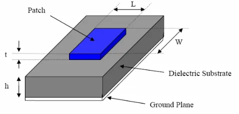
Dimensions of a Micro-strip patch antenna depend on the resonant frequency. The rectangular micro-strip patch antenna shown in Fig. 1 is normally consists of a rectangular metallic radiating patch of size Lp×Wpincorporated to
one side of a dielectric substrate of size Ls×Ws with relative permittivity Ɛr and thickness h, which has a metallic
ground plane on the other side. The radiating patch, which can take any possible shape as well the feeding network, which could be implemented with different techniques are usually photo-etched on the dielectric substrate.
Micro-strip antennas are used for number of wireless applications such as WLAN, WI-FI, Bluetooth and many other applications. The substrate should be chosen carefully because the substrate height as well as its dielectric constant play great roles on the antenna performance and its total size. The substrates that are most desirable for good antenna performance are the thick substrates whose dielectric constant is low, these provide better radiation efficiency, higher directivity, and wider bandwidth, but at the expense of larger element size.
Design Procedure:
For designing of a Micro-strip patch antenna, the resonant frequency and a dielectric medium for which antenna is to be designed, is selectedthe parameters are calculated as,
Width of the patch(W):
The width of the patch is calculated using the equation,
W= (1)
Where,
W = Width of the patch Co = Speed of light
Ɛr = Value of the dielectric substrate
Effective refractive index:
The effective refractive index value of a patch is an important parameter in the designing procedure of a micro-strip antenna. The radiations travelling from the patch towards the ground pass through air and some through the substrate. Both the air and substrates have different dieletric values, therefore in order to account this we find the value of effective dielectric constant. The value of the effective dielectric constant is,
Ɛreff = + [1+12 ] ,W/h>1(2)
Length:
Electrically the size of the antenna is increased be an amount of (ΔL).Therefore the length of the patch is,
= 0.412 (3)
Where ‘h’ =height of the substrate
The length(L) of the patch is now to be calculated using the below mentioned equation,
L = (4)
Length and Width of Ground plane:
The length and width of a substrate is equal to that of the ground plane. Then it is calculated as, Lg = 6h+L(5)
Wg = 6h+W(6) Return Loss:
Return Loss is the difference in decibels between the incident and reflected signals, R(dB) = 20log(VSWR-1)(VSWR+1)(7)
III. SIMULATION RESULTS
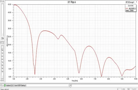
Fig 3: The Return Loss
is1.5dB. This indicates the impedance matching between the field and the load on VSWR then the value should be equal to 1 in an ideal situation but not realizable practically. In other words, practically it should be less than 2 but greater than 1 for good operation of the antenna. Simulated results of 3D Radiation pattern is also represented in this design. Radiation pattern refers to the direction of the electromagnetic waves radiates away from the antenna. It is a graphical representation of radiation properties of the micro-strip patch antenna. The radiation patterns of the antenna isomnidirectional.
Fig 4: The Radiation Pattern of antenna
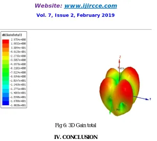
Fig 6: 3D Gain total
IV. CONCLUSION
The antenna is having return loss of -17.5dB at 5.8GHz. This designed antenna is simulated on HFSS software. For this antenna, a sufficient band-width was achieved by utilizing micro-strip line technique, the desired frequency 5.8GHz is achieved. Likewise the VSWR value of 1.5 is achievable. The structure is built on FR-4 substrate of 4.4 dielectric constant. The proposed antenna is very compact, very easy to fabricate. The designed micro-strip antenna is optimized for 5G communication. Further the Gain and directivity of antenna can be improved by using mete-materials into the path.
REFERENCES
1. Mohamad Bakryel_Mashade& E. A. Hegazy, Design and Analysis of 28GHz Rectangular Micro-strip Patch Antenna Array,january 2015. 2. Atima Agarwal, Simulation and Analysis of 5G Mobile Phones Antenna,septemper 2016.
3. Atik Mahabub1, Md. Mostafizur Rahman1, Design of a Multiband Patch Antenna for 5G Communication Systems, at 2018.
4. J.J. Tiang, M.T.Islam, N. Misran, and J.S.Mandeep,Circular Micro-strip Slot Antenna for Dual Frequency RFID Application, Progressive Electromagnetics Research, 2011
5. N. Saini and V. Kumar, “A Review on Microstrip Patch Antenna for UHF RFID Tag Applications Mounted on Metallic Surface,” Int. J. of Electrical & Electronics Engineering (IJEEE), Vol. 1, Issue 2, April 2014, pp. 14-18.
6. P.A. Nawale1, Prof. R.G. Zope, Rectangular Micro-strip Patch Antenna For 2.4 GHz and Communication Using Defected round Structure.
7. Shera Prabjyot Singh1, Ashish Singh2, Design and Fabrication of Micro-strip Patch Antenna at 2.4 Ghz for WLAN Application using HFSS, at 2016.