20th International Conference on Structural Mechanics in Reactor Technology (SMiRT 20) Espoo, Finland, August 9-14, 2009 SMiRT 20-Division 8, Paper 1986
Development and In-reactor Verification
of Three Types of Advanced Nuclear Fuels for PWRs
Young Ki Jang
a, Kyeong Lak Jeon
a, Yong Hwan Kim
a, Jae Ik Kim
a, Jung Cheol Shin
a,
Man Su Kim
b, Tae Hyoung Lee
band Jong Ryul Park
aa
Nuclear Fuel Technology Department, Korea Nuclear Fuel, Yuseong, Daejeon, 305-353, Korea, e-mail: [email protected]
b
Korea Hydro & Nuclear Power Co., Ltd.
Keywords: Advanced, Nuclear, Fuel, In-reactor, Performance, Verification.
1
ABSTRACT
Three types of advanced fuels for PWRs are being verified in three Korean nuclear reactors: PLUS7TM for Optimized Power Reactor of 1000 MW class (OPR1000) and Advanced Power Reactor of 1400 MW class (APR1400), and 16ACE7TM and 17ACE7TM for 16x16 and 17x17 Westinghouse types of plants, respectively.
Each four lead test assemblies (LTAs) for each fuel type had been loaded to verify the irradiation performances in the commercial reactors. Four steps for in-reactor verification were being applied: the first one for assembly-wise examination in poolside after each cycle, the second one for rod-wise examination after disassembling in poolside, the third one for the rod examination in the hot cell test facility in detail, and the final one for the skeleton examination in the hot cell test facility in detail.
The first leading fuel, PLUS7TM, has completed 3 steps of verification and will start the final step from this year, while the 16ACE7TM has completed 2 steps and is waiting for the third and fourth steps until next year and the 17ACE7TM is being verified in reactor for the third cycle irradiation. The examination results up to now showed that all these 3 types of fuels were being irradiated successfully in the reactors.
The designs of these three types of advanced fuels are summarized and in-reactor performances on three types of advanced fuels are compared in this paper. In conclusion, all the irradiation performance parameters were within the expected design limits. In-reactor performances of these fuels are being verified continuously through the surveillance program during commercial implementation.
2
INTRODUCTION
Three types of advanced nuclear fuels for PWRs had been developed through the extensive out-of-pile tests. The irradiation performances of PLUS7TM for Optimized Power Reactor of 1000 MW class (OPR1000) and Advanced Power Reactor of 1400 MW class (APR1400) is being verified in Ulchin unit 3, while 16ACE7TM and 17ACE7TM for 16x16 and 17x17 Westinghouse types of plants are being verified in Kori units 2&3, respectively.
The objectives of the developments were to achieve higher batch average burnup up to 55 GWD/MTU, to increase 10 % overpower margin, to enhance neutron economy, to improve the mechanical integrity of higher seismic capability, debris-induced fretting wear performance and grid-to-rod fretting wear performance, and finally to improve manufacturability etc. The objectives to solve incomplete rod insertion problem and spring screw failure issue were added for the last two fuels.
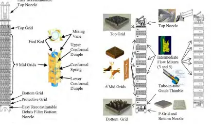
relieve IRI issue and top nozzle screw failure issue. Therefore, the design features of the integral top nozzle and tube-in-tube guide thimble were introduced as shown in Fig. 2. The other difference in design between 16ACE7TM and 17ACE7TM is the number of IFM grids. 16ACE7TM has 3 IFMs which exist between grid 4 and grid 7 as shown in Fig. 2 while 17ACE7TM has 2 IFMs on the upper two spans to enhance additional thermal margin, a total of 5 IFMs (2008a, 2008b, 2007).
Fig. 1 PLUS7TM fuel assembly Fig. 2 ACE7TM fuel assembly
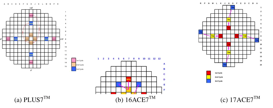
These fuels are being verified by the schedule shown in Fig. 3. The locations of the LTAs during 3 cycles of irradiation in reactor are shown in Fig. 4. All four PLUS7TM LTAs were irradiated in the symmetrical locations. Four PLUS7TM LTAs were near the core shroud for the first cycle, and at the center of the core for the second cycle, and finally between the center and the shroud for the final cycle. The poolside examinations (PSE) on these LTAs had been performed and evaluated after each cycle. 16ACE7TM were placed between the center and the shroud for the first cycle, and at the center of the core for the second cycle, and finally again between the center and the shroud for the final cycle. 17ACE7TM were placed at the center of the core for the first cycle, and between the center and the shroud for the second cycle, and in the core shroud for the final cycle.
Fig. 3 A procedure to verify in-reactor performance of advanced nuclear fuels
! A B C D E F G H J K L M N P R 180O 1 HA06 2 3 HA06 4 5 6 HA05 7 90O HA04 HA04 HA03 HA04 HA03 HA03 270O8 HA06 9 10 11 HA05 12 13 HA05 14 15 0O 1st Cycle 2nd Cycle 3rd Cycle
! A B C D E F G H J K L M N P R
180O 1 HA06 2 3 HA06 4 5 6 HA05 7
90O HA04 HA04 HA03 HA04 HA03 HA03 270O8
HA06 9 10 11 HA05 12 13 HA05 14 15 0O 1st Cycle 2nd Cycle 3rd Cycle
(a) PLUS7TM (b) 16ACE7TM (c) 17ACE7TM
Fig. 4 Advanced LTA locations for 3 cycles in reactors
Each four lead test assemblies (LTAs) for each fuel type had been loaded to verify the irradiation performances in the commercial reactors. Four steps for in-reactor verification were being applied: the first one for assembly-wise examination in poolside after each cycle, the second one for rod-wise examination after disassembling in poolside, the third one for the rod examination in the hot cell test facility in detail, and the final one for the skeleton examination in the hot cell test facility in detail. As a first step, assembly-wise examinations are performed in the poolside without disassembling LTAs during the refueling outages. Eight burnup-dependent performance parameters were selected to be measured and evaluated, such as assembly length growth, assembly bow, assembly twist, grid width growth, rod length growth, rod bow, rod creepdown, and cladding oxide layer thickness, etc. After 3 cycle irradiations, one LTA is disassembled and rods are inspected thoroughly for the second step. Five burnup-dependent parameters were selected, such as the reconstitution performance to check convenience or easiness during disassembly/re-assembly, rod drag force to compare grid cell sizes indirectly, and rod diameter, cladding wear depth and cladding oxide thickness, etc. After the rod inspections in the poolside, 10 rods and skeleton are sent to the hot cell facility to examine performance parameters more thoroughly for the third and fourth steps.
The first leading fuel, PLUS7TM, has completed 3 steps of verification and will start the final step from this year while the second 16ACE7TM has completed 2 steps and is waiting for the third and fourth steps until next year and the last 17ACE7TM is being verified in reactor for the final third cycle irradiation. The examination results up to now showed that all the 3 fuels were being irradiated successfully in the reactors.
In the meanwhile, the commercial implementation was started by expecting the performances during the 3rd cycle irradiation from those during the 2nd cycle irradiation. PLUS7TM had been supplied commercially to all eight operating OPR1000s from 2006 and will be additionally supplied to four OPR1000s and four APR1400s under construction. 16ACE7TM was supplied to Kori unit 2 last year, and 17ACE7TM was supplied to the first 17x17 Westinghouse type plant and will be supplied to the other five 17x17 Westinghouse type plants in order of precedence.
R P N M L K J H G F E D C B A
T91 1 2 3 T91 4 5 T91 6 T92 7
T92 T92 T93 T39 8
T939 T94 10 11 T94 12 13 14 T94 15 1st Cycle 2nd Cycle 3rd Cycle
1 2 3 4 5 6 7 8 9 10 11 12 13
A B C W91 D E F
180° W92 W93 G
The designs and in-reactor performances of these three types of advanced fuels are summarized compared in this paper. In conclusion, all the irradiation performance parameters were showed within the expected design limits. In-reactor performances of these fuels are being verified repeatedly through the surveillance program during commercial implementation.
3
EXAMINATIONS IN POOLSIDE AND IN HOT CELL
Visual examinations were performed on four LTAs using the high density camera during fuel unloading after each cycle. More accurate measurements were performed using four measurement equipments: equipment for dimensional measurement, linear variable differential transducer equipment (LVDT) for grid width measurement, another LVDT for rod outer diameter measurement and eddy current test equipment (ECT) for rod oxide thickness measurement. Fig. 5 shows the measurement of performance parameters on assembly grappled in handling machine by using the equipment installed on the elevator in poolside.
The fuel assembly length increase can cause an effect on the compatibility with reactor internals as well as the interference between nozzle and fuel rod. Fuel assembly length change is calculated from the difference between the post-irradiation and pre-irradiation fuel assembly length. The fuel assembly grappled at the handling tool is measured using an encoder corresponded by a calibrated measuring tape. Each fuel assembly elevations along the center of the four faces are measured on two LTAs each.
The analyses of the videotapes are utilized for the four parameters: top nozzle-rod gap, rod-to-rod gap, and assembly bow and twist. As the fuel rods are nearly contacted on the bottom nozzle, they are restricted to grow only toward the top nozzle. Fuel rod growth can be estimated by adding top nozzle-rod gap decrease to the fuel assembly growth. When analyzing the videotape of top nozzle-rod gap, all the other gaps are calculated relatively after measuring a gap at the center of assembly during the assembly length measurement as a reference. The excessively closer gap between rods due to rod bow results in DNB penalty. This phenomenon generally occurs when the rods cannot grow axially due to excessive force by the grid springs. After videotaping all rods at the center of the spans between adjacent grids, rod-to-rod gaps are calculated relatively by using outer diameters of two rods on the both sides as the references. Fuel assembly bow and twist can cause an effect on loading and unloading fuel assemblies. For assembly bow, two rod cells and a vertical line installed on the right side of fuel assembly at each grid elevation is videotaped. And then, the distances between the grids and a line are compensated by using the grid cell sizes at the same elevation as the references. For assembly twist, the fuel assembly top and bottom nozzles and two vertical lines installed on the right side of fuel assembly is videotaped. And then, the angles between top (and bottom) nozzle and a plane formed by two lines are determined. Finally, fuel assembly twist is determined by the relative angle between top nozzle-to-the plane and bottom nozzle-to-the plane.
The spacer grid plays an important role to support rods. The excessive width can impact loading and unloading fuel assemblies into the reactor as well as the compatibility with the reactor core shroud. The calibration of LVDT system by using a standard is performed before and after measuring spacer grid widths. The minimum spacer grid width is obtained by twisting the jaw of LVDT equipment forward and backward or up and down.
The outside diameters of the peripheral rods in one LTA for each advanced fuel are measured using LVDT equipment. This equipment is also calibrated by using a standard. Ten fuel rods per assembly were selected by considering fuel rod burnup. Five axial elevations per rod were selected to get axial distribution of cladding creepdown or pellet swelling. The cladding oxide thickness is measured using ECT equipment. This equipment was also calibrated using the oxidized standards. The measurements are performed by two steps. As the first step, all rods on a row on the face of higher burnup and over 10 axial positions per rod were selected to evaluate axial distribution of cladding oxide thickness. After finding out the elevation having axially peak oxide thickness, as the second step, almost all measurable rods at that elevation were measured to find out which rod has the maximum oxide thickness of the LTA.
Fig. 5 Equipment for poolside examination on the elevator and assembly grappled in handling machine
Fig. 6 Rod examination after disassembling
an LTA in poolside
4
EXAMINATION RESULTS AND CONSIDERATION
Visual examinations on all LTAs showed that top nozzle springs, fuel rod welding integrity, fuel cladding and grids were in good condition. The analyses of power history, coolant activity etc. show that the LTAs were irradiated symmetrically within the expected design range and the reactor cores having the LTAs did not show any anomalies including fuel failure, etc.
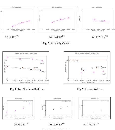
The fuel assembly lengths related to the compatibility with reactor internals as well as the interference between nozzle and fuel rod were measured and evaluated. Even though the fuel assembly lengths increase after each cycle and the design margins are reduced, there are still enough margins as shown in Fig. 7. It is evaluated that three types of advanced fuels still have enough margins from the assembly growth point of view. The minimum top nozzle-rod gap determined by initial gap, assembly growth and rod growth should be positive during fuel lifetime. The evaluation results on the top nozzle-rod gap shows there are a lot of margins after each cycle on three types of advanced fuels as shown in Fig. 8. The excessively close gap between rods due to the spring force of spacer grid may result in DNB penalty in an operating reactor. Fig. 9 shows the limiting gap size after each cycle is greater than the design limit. It is evaluated that all advanced fuels have a margin from the rod-to-rod gap point of view. Fuel assembly bow and twist are determined by analyzing the videotapes. The excessive bow or twist can impact on the compatibility to reactor internals as well as on the fuel loading and unloading. The amounts of bows or twists at each cycle are within their design limits. It is concluded that all advanced fuels have the design margins from the assembly bow or twist points of view. The spacer grid width directly measured by LVDT is grown by the irradiation exposures. Fig. 10 shows the largest grid widths on the upper region after each cycle are lower than the design criterion and still have the design margin. It is, therefore, concluded that all advanced fuels have the design margins from the grid width point of view.
PLUS7 Assembly Growth
0 25
0 10,000 20,000 30,000 40,000 50,000 60,000
Assembly Burnup, MWD/MTU
G ro w th , m m _
16ACE7 Assembly Growth
0 10
0 10,000 20,000 30,000 40,000 50,000 60,000
Assembly Burnup, MWD/MTU
G ro w th , m m _
17ACE7 Assembly Growth
0 10
0 10,000 20,000 30,000 40,000 50,000 60,000
Assembly Burnup, MWD/MTU
G ro w th , m m _
(a) PLUS7TM (b) 16ACE7TM (c) 17ACE7TM
Fig. 7 Assembly Growth
Shoulder Gaps of PLUS7, 16ACE7 and 17ACE7
0 50
0 10,000 20,000 30,000 40,000 50,000 60,000
Assembly Burnup, MWD/MTU
Sh ou ld er G ap , m m _ PLUS7 17ACE7 16ACE7
Channel Closures of PLUS7, 16ACE7 and 17ACE7
0 50
0 10,000 20,000 30,000 40,000 50,000 60,000
Assembly Burnup, MWD/MTU
C ha nn el C lo su re , % PLUS7 17ACE7 16ACE7
No penalty on DNB
Fig. 8 Top Nozzle-to-Rod Gap Fig. 9 Rod-to-Rod Gap
Grid Width of PLUS7
206 207.5
0 10,000 20,000 30,000 40,000 50,000 60,000 Assembly Burnup, MWD/MTU
W id th , m m _
Assembly Pitch = 207.77mm
Grid Width of 16ACE7
196 197.5
0 10,000 20,000 30,000 40,000 50,000 60,000
Assembly Burnup, MWD/MTU
W id th , m m _
Assembly Pitch = 198.2 mm
Grid Width of 17ACE7
213 214.5
0 10,000 20,000 30,000 40,000 50,000 60,000 Assembly Burnup, MWD/MTU
W id th , m m _
Assembly Pitch = 215.2 mm
(a) PLUS7TM (b) 16ACE7TM (c) 17ACE7TM
Fig. 10 Grid Width Growth
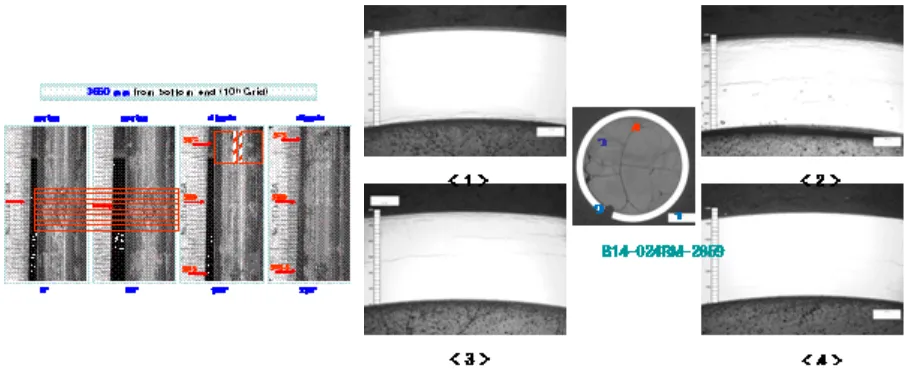
Fig. 11 Clad wear position contacting to grid spring in hot cell (typical)
5
CONCLUSION
In-reactor verifications on three types of advanced fuels are being performed by following the verification procedure. Three cycle irradiation of PLUS7TM and 16ACE7TM had been completed while the third cycle irradiation of the last fuel, 17ACE7TM, is being run. All burnup-dependent parameters were below their design limits without any anomalies. It is, therefore, concluded that three advanced fuels are successfully being irradiated. By expecting the irradiation performances after three cycles to be within the design limits from the evaluation results after two cycle irradiation, all three advanced fuels could start to supply to 15 nuclear power plants in Korea commercially. As a result, the Guardian fuels in all 8 OPR1000s, the Standard fuels in Kori unit 2 and the RFA fuels in six 17x17 Westinghouse type reactors are being replaced with PLUS7TM, 16ACE7TM and 17ACE7TM, respectively. The examinations on rods and skeleton in hot cell are being performed for the detail verification. In addition, in-reactor performance verifications of these fuels are being repeated through the surveillance program during commercial implementation.
Acknowledgements. This study was carried out under the project “Development of the Fuel Performance
Examination Technology” which was funded by the Ministry of Commerce, Industry and Energy in Korea.
References
Kim K. T., Kim Y. H., Jang Y. K., Stucker D. L., 2002. PLUS7TM Advanced Fuel Development for the CE 16x16 Type Nuclear Power Plants. The 13th Pacific Basin Nuclear Conference.
Jang Young Ki, Jeon Kyeong Lak, Kim Kyu Tae, Kim Jae Ik, Park Jong Ryul, 2008a. Irradiation Performances of Korean Advanced Fuels for Nuclear Power Plants. The 16th Pacific Basin Nuclear Conference.
Jang Young Ki, Jeon Kyeong Lak, Kim Jae Ik, Kim Yong Hwan, Park Jong Ryul, 2008b. In-reactor Performance of Advanced Fuel, 16ACE7TM, for Kori 2 Nuclear Power Plant. 2008 Water Reactor Fuel Performance Meeting.