MODBUS: A Novel Approach in Security
and Monitoring
Kiran A. Chaudhari1, Kalpesh L. Mahajan1 , Aishwarya S. Pawar1, Amruta M. Patole1, Pranav Dahiwal2*
B.E. Student, Department of Electronics and Telecommunication, Deogiri Institute of Engineering and Management
Studies, Aurangabad (MS), India1
Director, Department of R&D, Aakruti Electronics Pvt. Ltd, Aurangabad (MS), India2
ABSTRACT: The proposed system is developed with the help of microcontroller PIC16 which acquire data from sensors. Microcontrollers are connected in single master multi-slaves mode for communication. Master acquires data from slave’s networks with the help of Protocol called MODBUS/RTU and the physical medium RS 485.The data is transmitted through CAT-6 cable. Only one device (i.e. the master) can initiate communication. The other devices (i.e. slaves) respond to the masters communication messages. They either send back the requested data or perform the requested operation. The master can talk with individual slave units (unicast message) or all slave units at one time (i.e. broadcast messages). Regardless of the transmission 'mode' RTUthe communication cycle and contents remains the same. The data to be stored are available in values of the slave registries MODBUS in MODBUS network. Any instrument be it an indicator, a controller, a sensor, and others, can be considered a slave on the network since it has available a MODBUS/RTU communication port.
KEYWORDS: PIC16F887 Controller, RS485, MODBUS, CAT -6 cable, RTU.
I. INTRODUCTION
It is very common that the devices distributed over the plant to act, measure and control be interconnected by a communication network. In industrial environments there is always need for analyzing the behavior of a process through its variables, and a data acquisition system can be the solution. Data acquisition is the process that measures an electrical or physical phenomenon such as voltage, current, temperature, frequency etc. Every data acquisition system shares a common goal in order to acquire, analyze and present the information. Data acquisition systems incorporate signals, sensors, actuators, signal conditioners, data acquisition devices and application software.In the power industry, real-time performance and reliability of the data acquisition system is very important. As the performance of instability which leads to various thermal and electrical parameters in the production process of false positives is serious, it will cause generator set shutdown, and severely affect the life of generator set and safety of the grid.
In industrial automation an industrial network is defined as the communication protocols used to supervise and control a given process, such as a quick and precise exchange of data between sensors, actuators, computers, programmable logic controllers (PLC) among others. Usually Modbus is used with big controllers and PLC’s so that the whole system becomes costly. Therefore small scale industries cannot afford that expense though they need security and monitoring of different sections of the company. Therefore we have designed a cost effective, small in size, flexible system which is suitable in any application where security and monitoring is needed. PIC controller itself is a good solution for industrial applications because its effective features and most important its high temperature capacity. We have used PIC as a controller and whole monitoring of the rooms is done by the PIC microcontrollers through Modbus protocol. Thus the system becomes very cost effective and small in size as well as suitable for industrial applications.
also provide security and monitoring facilities. This system is very flexible so that it can be implemented in commercial as well as industrial applications. Since only single cable i.e. CAT-6 is used, reduces the complexity of the whole system. Backup looping is provided therefore the chances of barrier in communication due to broken cables are less.
II. RELATED WORK
Mr. Kelong Wang [1] proposed system for power plant control of the embedded data acquisition system. It
had been developed from centralized control, distributed control into field bus control. The paper puts forward a design program combining Modbus communication protocol with 32-bit ARM Coretx-MO microprocessor as its core.Yunfeng Zhao ,Yahui Wang [2] design a MODBUS based data acquisition system to collect the fault signals involving current, voltage and harmonic, which can provide real-time and accurate fault data for the analysis and calculation in the building electrical fault diagnosis system.Andre Jorge, Joao Guerreiro, Pedro Pereira, Joao Martins and Luis Gomes UNINOVA – CTS[3] describes the development of an open source system for monitoring and data acquisition of several energy analyzers. The developed system is based on a computer with Internet/Intranet connection by means of RS485 using Modbus RTU as communication protocol.Gianluca Cena [4] stated that currently, the only
two choices available for the underlying network, specified by the MODBUS standard ,rely on serial lines and the
TCP/IP protocol stack. In this paper at third solution is introduced, known as MODBUS CAN, that is stacked above CAN. With respect to MODBUS RTU, MODBUS CAN offers noticeably higher performance.
III. SYSTEMDEVELOPMENT
A. HARDWARE
Fig.1 shows different blocks of the proposed system. A scheme that is presented here to get data from various control room (i.e. from slave) to master by using embedded system. Modbus protocol serves for this purpose which is use in various industries applications. Electrical standard is use for serial communication between the systems. The proposed system consists of different module such as
1. Power supply 2. Microcontroller 3. RS 485 module 4. Display Panel Module
Microcontroller:PIC 16F877 is one of the most advanced microcontroller from Microchip. In proposed system PIC controller used as master & slave. Different sensors like temperature, PIR are connected to ports of slave & display device are connected to master controller. It is ideal for applications such as machine control applications, measurement devices, study purpose, and so on. The PIC 16F877 features all the components which modern microcontrollers normally have.
RS485: RS-485 is the common names for serial communications standards. The standards, defined by the Electronics Industry Association, is more correctly named and EIA/TIA-485. RS-485 communicates digital information over twisted pair wire from transmitters to receivers. Devices can be up to 4000 feet (1220 meters) apart before repeaters are required. Up to 32 RS-485 transceivers can occupy a bus. RS-422/485 systems can communicate at rates up to 10 Mbps (though most systems operate at lower bit rates). Both systems utilize balanced outputs and differential inputs, which provide better noise immunity than single-ended systems such as RS-232.MAX485, are low-power transceivers for RS-485 and RS- 422 communication. Each part contains one driver and one receiver.
Features:
Low Quiescent Current: 300μA -7V to +12V
Common-Mode Input Voltage Range
Three-State Outputs 30ns Propagation Delays, 5ns Skew
Operate from a Single 5V Supply
Allows up to 32 Transceivers on the Bus Data rate: 2.5 Mbps
Network topology with RS485:
Network topology is probably the reason why RS485 is now the favorite of the four mentioned interfaces in data acquisition and control applications. RS485 is the only of the interfaces capable of internetworking multiple transmitters and receivers in the same network. When using the default RS485 receivers with an input resistance of 12kΩ it is possible to connect 32 devices to the network. Currently available high-resistance RS485 inputs allow this number to be expanded to 256. RS485 repeaters are also available which make it possible to increase the number of nodes to several thousands, spanning multiple kilometers. And that with an interface which does not require intelligent network hardware: the implementation on the software side is not much more difficult than with RS232. It is the reason why RS485 is so popular with computers, PLCs, micro controllers and intelligent sensors in scientific and technical applications.
Modbus protocol
MODBUS Master / Slaves protocol principle:
The MODBUS Serial Line protocol is a Master-Slaves protocol. Only one master (at the same time) is connected to the bus, and one or several (247 maximum number) slaves nodes are also connected to the same serial bus. A MODBUS communication is always initiated by the master. The slave nodes will never transmit data without receiving a request from the master node.
Two-Wire interface is the most common. As an add-on option, RS485 Four-Wire interface may also be implemented. A TIA/EIA-232-E (RS232) serial interface may also be used as an interface, when only short point to point communication is required. Fig.3 gives a general representation of MODBUS serial communication stack compared to the 7 layers of the OSI model.
Fig.3ISO/OSI model Fig 4.RTU Transmission
As shown in fig.4 MODBUS RTU transmssion is carried out.The packet of data to be transmitted is made from different sections such as address of the slave, Function code, Data and CRC.CRC is used for the Data security .
B. SYSTEM FLOW
1. Master Operation
Fig.5: Master state diagram
cannot send a second request at the same time. When a unicast request is sent to a slave, the master goes into "Waiting for reply" state, and a “Response Time-out” is started. It prevents the Master from staying indefinitely in "Waiting for reply" state. Value of the Response time-out is application dependant.When a reply is received, the Master checks the reply before starting the data processing. The checking may result in an error, for example a reply from an unexpected slave, or an error in the received frame. In case of a reply received from an unexpected slave, the Response time-out is kept running. In case of an error detected on the frame, a retry may be performed.If no reply is received, the Response time-out expires, and an error is generated. Then the Master goes into "Idle" state, enabling a retry of the request. The maximum number of retries depends on the master set-up.When a broadcast request is sent on the serial bus, no response is returned from the slaves. Nevertheless a delay is respected by the Master in order to allow any slave to process the current request before sending a new one. This delay is called "Turnaround delay". Therefore the master goes into "Waiting Turnaround delay" state before going back in "idle" state and before being able to send another request.In unicast the Response time out must be set long enough for any slave to process the request and return the response, in broadcast the Turnaround delay must be long enough for any slave to process only the request and be able to receive a new one. Therefore the Turnaround delay should be shorter than the Response time-out. Typically the Response time-out is from 1s to several second at 9600 bps; and the Turnaround delay is from 100 ms to 200ms. Frame error consists of: 1) Parity checking applied to each character; 2) Redundancy checking applied to the entire frame.
2. Slave Operation
Fig.6.Slave state diagram
IV.SIMULATIONRESULTS
Fig.7: Designed System Configuration for master and slaves
Fig. 7 shows one of the slave connections to master throgh RS485.After testing the algorithm and code on the designed circuitry, the following simulation results observed.
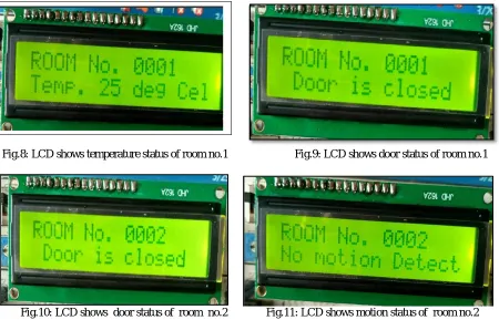
Fig.8: LCD shows temperature status of room no.1 Fig.9: LCD shows door status of room no.1
Fig.10: LCD shows door status of room no.2 Fig.11: LCD shows motion status of room no.2
on the LCD. In this result system aquire different data from the slaves which are located in different rooms, each slave provids data like temprature of room1,whether room are open or close, or anyone is enter in the roon by using motion sensor.
Fig.12 Display panel shows normal status of all the rooms Fig.13 Display panel shows door of room no.3 is opened.
These fig.12 & Fig 12 are the realtime display pannel at the control room where all the information is indicated with led states.Here all green led shows the Normal operations in the room &red led shows change in normal condition which require some control.
V. CONCLUSION AND FUTURE ASPECT
The simulation results showed that the proposed algorithm performs better. The use of PIC16F877 controller provides reliability and fast response. The proposed algorithm provides the smart controlling to the entire system and maximizes the lifetime of the system and provides safety to human operators. This provides effective control over the specified ranges of air and water pressure.Since only single cable i.e. CAT-6 is used, reduces the complexity of the whole system. Backup looping is provided therefore the chances of barrier in communication due to broken cables are less. According to requirement for the industrial application we have selected the required components which are being used for the system development. Since the proposed system is very flexible it can be converted as wireless in future and the data accessed from different sensors of different rooms can be send to remote location and the same data can be monitored from there using IOT(Internet of things).
ACKNOWLEDGEMENT
Completion of our dissertation is a task which would have not accomplished without cooperation and help from our
guide. At the outset, we wish to express our deep sense of gratitude to our guide Prof. P. M. Soni for her guidance and
constant encouragement without which it would have not been possible. We are also highly indebted to our Head of
Department Dr. R. M. Autee for his encouragement, guidance and allowing us to use all the facilities in the
department. We are also very much thankful to our director Dr. U. D. Shiurkar for his constant support and
encouragement.
Lastly but certainly not the list we also thank other staff members, our colleagues and all those people associated with this project and appreciate their kind co-operation.
REFERENCES
[1] Kelong Wang “Implementation of Modbus Communication Protocol Based on ARM Coretx-MO” 2014 IEEE International Conference on System Science ang Engineering (JCSSE) July 11-13 2014,Shanghai, China
[2]Yunfeng Zhao,Yahui Wang, Hong Ren, Mingjia Ding “Design of a Data Acquisition System for Building Electrical Fault Diagnosis” Beijing University of Civil Engineering and Architecture, Beijing 100044978-1-4799-7016-2/15/$31.00_c 2015 IEEE
[3] Andre Jorge, Joao Guerreiro, “Energy Consumption Monitoring System for Large Complexes”,UNINOVA – CTS Univer sidade Nova de Lisboa - Faculdade de Ciências e Tecnologia
[4]Gianluca Cena, “Design,Verification,andPerformanceofaModbus–CANAdaptationLayer” 978-1-4799-3235-1/14/$31.00 ©2014 IEEE
[5]A Soetedjo, K. Yamada, “A new approach on red color thresholding for traffic sign recognition system,” Journal of Japan Society for Fuzzy Theory and Intelligent Informatics, Vol. 19, No. 5, pp. 457-465, 2007.