University of Windsor University of Windsor
Scholarship at UWindsor
Scholarship at UWindsor
Electronic Theses and Dissertations Theses, Dissertations, and Major Papers
2014
Incorporating Interlocked Molecules into Self-Assembled
Incorporating Interlocked Molecules into Self-Assembled
Monolayers
Monolayers
Michael Alexander Bolla University of Windsor
Follow this and additional works at: https://scholar.uwindsor.ca/etd
Recommended Citation Recommended Citation
Bolla, Michael Alexander, "Incorporating Interlocked Molecules into Self-Assembled Monolayers" (2014). Electronic Theses and Dissertations. 5217.
https://scholar.uwindsor.ca/etd/5217
This online database contains the full-text of PhD dissertations and Masters’ theses of University of Windsor students from 1954 forward. These documents are made available for personal study and research purposes only, in accordance with the Canadian Copyright Act and the Creative Commons license—CC BY-NC-ND (Attribution, Non-Commercial, No Derivative Works). Under this license, works must always be attributed to the copyright holder (original author), cannot be used for any commercial purposes, and may not be altered. Any other use would require the permission of the copyright holder. Students may inquire about withdrawing their dissertation and/or thesis from this database. For additional inquiries, please contact the repository administrator via email
Incorporating Interlocked Molecules
Into Self-Assembled Monolayers
By
Michael Bolla
A Dissertation
Submitted to the Faculty of Graduate Studies through the Department of Chemistry and Biochemistry
in Partial Fulfillment of the Requirements for the Degree of Doctor of Philosophy
at the University of Windsor
Windsor, Ontario, Canada
2014
Incorporating Interlocked Molecules into Self-Assembled Monolayers
by
Michael Bolla
APPROVED BY:
__________________________________________________ J. Wisner, External Examiner
Western University
__________________________________________________ D. Haffner
Great Lakes Institute for Environmental Research
__________________________________________________ H. Eichhorn
Department of Chemistry & Biochemistry
__________________________________________________ J. Rawson
Department of Chemistry & Biochemistry
__________________________________________________ T. Carmichael, Co- Advisor
Department of Chemistry & Biochemistry
__________________________________________________ S. Loeb, Co- Advisor
Department of Chemistry & Biochemistry
iii
Declaration of Originality
I hereby certify that I am the sole author of this dissertation and that no part of
this dissertation has been published or submitted for publication.
I certify that, to the best of my knowledge, my dissertation does not infringe upon
anyone’s copyright nor violate any proprietary rights and that any ideas, techniques,
quotations, or any other material from the work of other people included in my
dissertation, published or otherwise, are fully acknowledged in accordance with the
standard referencing practices. Furthermore, to the extent that I have included
copyrighted material that surpasses the bounds of fair dealing within the meaning of the
Canada Copyright Act, I certify that I have obtained a written permission from the
copyright owner(s) to include such material(s) in my dissertation and have included
copies of such copyright clearances to my appendix.
I declare that this is a true copy of my dissertation, including any final revisions,
as approved by my dissertation committee and the Graduate Studies office, and that this
dissertation has not been submitted for a higher degree to any other University or
iv
Abstract
This dissertation presents the design, synthesis and characterization of a set of
bis(pyridinium)ethane and dibenzo-24-crown-8 based systems that form self-assembled
monolayers on a gold substrate. Chapter 1 introduces the concept of interpenetrated and
interlocked molecules, molecular machines and self-assembled monolayers with
representative examples found in the literature. Chapter 2 provides an introduction to the
various surface characterization techniques that were employed.
In chapter 3, an interpenetrated system capable of forming self-assembled
monolayers on a gold substrate is described. The chapter begins with the design and
synthesis of the linker molecule. The recognition site was then synthesized, stoppered at
one end with 3,5-lutidine and terminated at the other end with a thioacetate protected
mercaptoundecanoic acid. SAMs were formed and characterized through RAIRS. While
confirmation of SAM formation was acquired, evidence that the macrocycle was present
could not be obtained.
Chapter 4 describes the synthesis and characterization of slippage [2]rotaxanes.
The rotaxanes were stoppered at one end with cyclohexyl isonicotinate and the other end
with a 3,5-substituted phenyl ring. The kinetic and thermodynamics showed association
constants strong enough to isolate the [2]rotaxanes with substituted DB24C8
macrocycles. The synthesis was redesigned with diphenylmethyl as a protecting group
since it is able to be removed without damaging the recognition site. SAMs, with and
without the macrocycle, were formed and characterized using RAIRS, EIS, XPS, and
contact angle measurements. The SAMs formed were seen to be loosely packed, even
v
formation were conducted. While this may have been successful, it was unclear due to
intercalation of DMSO into the SAM.
Chapter 5 describes attempts to improve the packing of the SAM by using a
co-adsorbent. Mixed SAMs were formed with the slippage system, using
mercaptoundecanoic acid as the co-adsorbate. The mixed SAMs were characterized at
various ratios of the adsorbates. After determining the ideal ratios of each compound for
the best packing of the SAM, further attempts at removal of the macrocycle were
conducted using DMSO, however, intercalation of DMSO into the SAM was still an
issue.
vi
Acknowledgements
First of all, I would like to thank my supervisors, Dr. Loeb and Dr. Carmichael for
all of their help, support and guidance throughout the years and for the opportunity to
work with both of their lab groups.
I would also to thank Greg Davidson, Jan Müller and Ronan San Juan. They
taught me the basics of surface chemistry in the laboratory and helped me to learn how to
conduct all of the characterization techniques that were used in this project. They also
helped me to understand and interpret the data acquired in my studies.
The rest of the lab group members, from both Dr. Carmichael and Dr. Loeb
groups have been very helpful. If there was ever anything I needed, such as more gold,
or any questions that I needed help answering, they were always there, willing to help.
Lastly, I would also like to thank the technicians, namely Mike Fuerth and Matt
Revington for their help with the NMRs and Joe for his help with all the other tech issues
vii
Table of Contents
Declaration of Originality ... iii
Abstract ... iv
Acknowledgements ... vi
List of Figures ... xiii
List of Tables ... xix
Abbreviations ...xxv
Chapter 1: Introduction ...1
1.1 Mechanically Interlocked Molecules ...1
1.1.1 What is Supramolecular Chemistry? ...1
1.1.2 Host Guest Interactions ...2
1.1.3 Interpenetrated and Interlocked Molecules ...2
1.1.4 Pseudorotaxanes ...3
1.1.5 Rotaxanes ...4
1.1.6 Synthetic Routes for Rotaxanes...5
1.1.7 Nomenclature ...7
1.1.8 Recognition Sites ...7
1.2 Molecular Switches based on MIMs ...9
1.2.1 Molecular Machines ...9
1.2.2 Brownian Motion ...10
1.2.3 Opening, Closing and Translocation ...10
1.2.4 Threading and Dethreading ...11
viii
1.2.6 Flip Switches ...13
1.2.7 Circumrotational Motion (Catenanes) ...14
1.2.8 Rotary Motion ...15
1.3 Thin Films and Self Assembled Monolayers ...17
1.3.1 Langmuir-Blodgett films ...17
1.3.2 Self-Assembled Monolayers ...17
1.3.3 SiO2 Self-Assembled Monolayers ...18
1.3.4 Thiol Self-Assembled Monolayers ...19
1.3.5 The Gold Surface ...19
1.3.6 SAM Formation - Kinetics and Thermodynamics ...21
1.3.7 Characteristics ...22
1.3.8 Bulky Tail Groups ...23
1.4 Controlling Surface Properties ...24
1.4.1 Introduction ...24
1.4.2 Rotary motion ...24
1.4.3 Shuttling ...25
1.5 References ...28
Chapter 2: Surface Characterization Techniques ...31
2.1 Reflection-Absorbtion Infrared Spectroscopy ...31
2.2 Electrochemical Impedance Spectroscopy ...33
2.3 Contact Angle ...35
2.4 X-Ray Photoelectron Spectroscopy ...36
ix
Chapter 3: Design and synthesis of a [2]Pseudorotaxane for SAM formation ...40
3.1 Design Components and Rationale ...40
3.2 Formation of the Linker Molecule ...42
3.3 Synthesis and Characterization of a Model Compound ...45
3.4 Synthesis and Characterization of the Axle ...47
3.5 Physical-Organic Properties of the [2]Pseudorotaxanes ...50
3.6 Formation and Preliminary Study of SAMs by RAIRS ...54
3.7 Functionalized Crown Ethers ...56
3.8 Lessons from these studies ...60
3.9 Experimental Section ...61
3.9.1 General Comments ...61
3.9.2 Synthesis of 3-1 ...63
3.9.3 Synthesis of 3-2 ...65
3.9.4 Synthesis of 3-3 (Miyaura-Suzuki reaction) ...66
3.9.5 Synthesis of 3-4 (Reduction) ...67
3.9.6 Synthesis of 3-5[BF4] (Methylation) ...69
3.9.7 Synthesis of 3-6[BF4] ...71
3.9.8 Synthesis of 3-7[BF4] ...73
3.9.9 Synthesis of 3-8[BF4] ...75
3.9.10 Synthesis of 3-9[BF4]2 ...77
3.9.11 Synthesis of 3-10[BF4]2 ...79
3.9.12 Synthesis of [2]Pseudorotaxanes ...82
x
3.9.14 Synthesis of 3-12 ...85
3.10 References ...87
Chapter 4: Design and synthesis of a [2]Rotaxane for SAM formation ...88
4.1 Introduction ...88
4.2 The Concept of Slippage in [2]Rotaxane Synthesis ...89
4.3 Design Components and Rationale ...92
4.4 Synthesis of the Dumbbell for a Slippage [2]Rotaxane ...93
4.5 Synthesis of the Slippage[2]Rotaxane for Surface Attachment ...95
4.6 Physical-Organic Properties of the Slippage [2]Rotaxanes ...96
4.7 The Acetyl Protecting Group ...101
4.8 Design of a New Protecting Group ...102
4.9 Determination of the Slippage Properties; Kinetic and Thermodynamics ...104
4.10 Preparation and Study of SAMs Utilizing the Slippage Axle ...105
4.11 Preparation of New Crown Ethers for Slippage [2]Rotaxanes ...112
4.12 Kinetic Properties of [2]Rotaxanes with New Crown Ethers ...115
4.13 Preparation of Slippage [2]Rotaxanes with New Crown Ethers ...116
4.14 Preparation of SAMs from Slippage [2]Rotaxanes and Their Properties ...117
4.15 Removal of Crown Ether Wheel From Surface Bound [2]Rotaxane via Slippage ...119
4.16 Summary and Conclusions ...128
4.17 Experimental ...130
4.17.1 General Comments ...130
xi
4.17.3 Synthesis of 4-2 ...134
4.17.4 Synthesis of 4-3 ...135
4.17.5 Synthesis of 4-4[BF4] ...136
4.17.6 Synthesis of 4-5[BF4] ...138
4.17.7 Synthesis of 4-6[BF4]2 ...140
4.17.8 Synthesis of 4-7[BF4]2 ...142
4.17.9 Synthesis of [4-6 DB24C8][BF4]2 and [4-7 DB24C8][BF4]2 ...144
4.17.10 Synthesis of 4-8 ...148
4.17.11 Synthesis of 4-9 ...150
4.17.12 Synthesis of 4-10 ...151
4.17.13 Synthesis of 4-11[BF4]2 ...152
4.17.14 Synthesis of 4-12[BF4]4 ...154
4.17.15 Synthesis of 4-13[BF4] ...157
4.17.16 Synthesis of 4-14[BF4] ...159
4.17.17 Synthesis of 4-15[BF4] ...161
4.17.18 Synthesis of 4-16[BF4] ...163
4.17.19 Synthesis of 4-17[BF4] ...165
4.17.20 Synthesis of 4-18 ...167
4.17.21 Synthesis of 4-19 ...168
4.17.22 Synthesis of 4-20 ...169
4.17.23 Synthesis of [4-12 R4DB24C8][BF4]4 ...170
4.17.24 XPS Survey Scans ...175
xii
Chapter 5: Mixed Self Assembled Monolayers of Slippage [2]Rotaxanes ...178
5.1 Introduction: What are mixed SAMs? ...178
5.2 Finding the Right Co-Adsorbent ...180
5.3 Mixed SAMs of 4-12[BF4]4 and 11-Mercaptoundecanoic Acid ...187
5.4 Mixed SAMs with the Corresponding Slippage [2]Rotaxanes ...192
5.5 Crown Removal using Mixed SAMs ...198
5.6 Summary and Conclusions ...200
5.7 Experimental ...201
5.8 References ...203
Chapter 6: Summary and Conclusion ...205
References ...208
xiii
List of Figures
Figure 1-1 – An illustrated example of host (red) – guest (blue) interactions in the
formation of a supramolecular complex ...2
Figure 1-2 – An illustrated of the formation of a [2]pseudorotaxanes from its individual components. ...3
Figure 1-3 – Examples of [2]pseudorotaxanes by a) Das et al and b) Loeb et al. ...4
Figure 1-4 – An illustrated example of a [2]rotaxane ...5
Figure 1-5 – An illustrated example of the three synthetic routes for [2]rotaxane formation: a) threading followed by stoppering, b) clipping, and c) slippage ...6
Figure 1-6 – A paraquat based recognition site designed by Stoddart and coworkers ...7
Figure 1-7 – The recognition motif by Loeb and Wisner ...8
Figure 1-8 – The open (left) and closed (right) forms of a molecular machine based on a crown ether ring ...11
Figure 1-9 – An illustrated example of a molecular shuttle ...12
Figure 1-10 – A molecular shuttle designed by Stoddart and coworkers ...13
Figure 1-11 – An illustrated example of a flip-switch ...13
Figure 1-12 – A flip-switch system developed by Loeb and coworkers ...14
Figure 1-13 – An illustrated example of a [2]catenane capable of molecular motion ...15
Figure 1-14 – A unidirectional rotor as designed by Feringa and coworkers ...16
Figure 1-15 – An illustrated example of a well packed SAM ...18
xiv
Figure 1-17 – Two SAMs designed with bulky tail groups by Porter(left) and
Abruna(right) ...23
Figure 1-18 – Molecular rotors formed on a 2D substrate developed by a) Tour and b) Feringa ...25
Figure 1-19 – a) The molecular shuttle system by Leigh and coworkers which shuttles upon exposure of the SAM to UV light ...26
Figure 1-20 – The molecular shuttle developed by Stoddart and coworkers that is used form numerous molecular systems ...27
Figure 2-1 – The equivalent circuit models of the simplified Randles (left) and Randles (right) circuits, accompanied with ideal Nyquist (a) and Bode (b) plots. ...34
Figure 2-2 –A summary of all the surface energies and tangent angle present for a drop of liquid on a solid surface ...36
Figure 2-3 –The XPS of SAM on a gold coated silicon substrate with the high resolution spectra of the C1s peaks. ...38
Figure 3-1 – [2]Pseudorotaxane system based off a system by Loeb et al. ...40
Figure 3-2 – [2]Rotaxane system described by Loeb et al.. ...42
Figure 3-3 – [2]Pseudorotaxane system design for SAM formation ...43
Figure 3-4 – The a) Linker molecule, b) synthesis route of the linker molecule, and c) 1H NMR spectra of the linker molecule in its acid (top) and anhydride (bottom) forms ...44
Figure 3-5 – The synthetic route of the model compound ...46
Figure 3-6 – 1H NMR spectrum of model compound 3-6[BF4] with labelling scheme. ..47
xv
Figure 3-8 – 1H NMR of compound 3-10[BF4]2 ...50
Figure 3-9 – Variable temperature 1H NMR spectra of [3-10 ⊂DB24C8]4+in CD3CN. 51 Figure 3-10 – VT 1H NMR results as a plot of ln Keq vs 1/T ...52
Figure 3-11 – Partial RAIRS spectra of the SAMs formed ...55
Figure 3-12 – Synthetic route of the functionalized crown ether ...57
Figure 3-13 – Partial 1H NMR of a) compound 3-10[BF4]2 in CD2Cl2, b) an equimolar mixture of compound 3-10[BF4]2 and compound 3-12 in CD2Cl2, c) compound 3-12 in CD2Cl2, and d) an equimolar mixture of compound 3-10[BF4]2 and compound 3-12 in 60:40 MeNO2:CD2Cl2 ...58
Figure 4-1 – An energy schematic for the self assembly of rotaxanes by slippage ...90
Figure 4-2 – The slippage [2]rotaxanes by Loeb and coworkers ...92
Figure 4-3 – The slippage [2]rotaxane component for SAM formation ...92
Figure 4-4 –The a) unsuccessful and b) successful synthetic routes to compound 4-6[BF4]2 ...94
Figure 4-5 – 1H NMR spectrum of compound 4-6[BF4]2 in MeCN with labelling scheme. ...95
Figure 4-6 – The synthetic route of compound 4-7[BF4]2 ...96
Figure 4-7 – A series of partial 1H NMR spectra of 4-7[BF4]2 with DB24C8 in MeCN taken over eleven months ...98
Figure 4-8 – a) a plot of 1/[Rotaxane] vs T of the 1H NMR results and b) a linear fit of the data over the initial 25 days ...99
Figure 4-9 – The initial synthetic route of compound 4-11[BF4]2 ...103
xvi
Figure 4-11 – Partial NMR spectra of a) compound 4-11[BF4]2 in MeCN, b) compound
4-12[BF4]4 in MeCN and c) compound 4-12[BF4]4 in DMSO ...105
Figure 4-12 – The design of the model compounds 3-6[BF4] and 4-17[BF4] ...107
Figure 4-13 – The CH2 region of the RAIRS spectra of the model compounds, the free
axle and the [2]rotaxane ...109
Figure 4-14 – The Bode and Nyquist plots of the EIS results for SAMs of compound
4-12[BF4]4 and its corresponding [2]rotaxane fit with the Randles circuit. For the Bode
plots, the best fit (dashed) and experimental (solid) data is shown. ...111
Figure 4-15 – The high resolution XPS of the C1s region of the XPS results for the a) free
dumbbell and b) [2]rotaxane ...113
Figure 4-16 – The synthetic routes of the substituted crown ethers ...114
Figure 4-17 – A summary of the association data for the [2] rotaxanes of compound 4-12
BF4]4 with DB24C8 and the substituted crown ethers ...116
Figure 4-18 – The reaction for forming [2]rotaxanes with the various crown ethers ...117
Figure 4-19 – The Bode plot of the EIS results for SAMs of compound 4-12[BF4]4 and
the corresponding [2]rotaxanes with R4DB24C8 and the Nyquist Plots of the two new
[2]rotaxanes. For the Bode plots, the best fit (dashed) and experimental (solid) data is
shown. ...118
Figure 4-20 – An illustrated example of the SAM formation procedure ...120
Figure 4-21 – The Nyquist plots of the [2]rotaxanes before(left) and after(right) soaking
xvii
Figure 4-22 – a) The Bode plots of the crown removal studies with DB24C8 and b) a
summary of the EIS and contact angle data with the various macrocycles. For the Bode
plots, the best fit (dashed) and experimental (solid) data is shown. ...122
Figure 4-23 – The CH2 region of the RAIRS spectra of the crown ether removal studies
with DB24C8 ...125
Figure 5-1 – An illustrated example of a mixed SAM. ...178
Figure 5-2 – Bode and Nyquist plots of the EIS results of mixed SAMs of compound
4-12[BF4]4 and 1-undecanethiol. For the Bode plots, the best fit (dashed) and experimental
(solid) data is shown. ...183
Figure 5-c – Bode and Nyquist plots of the EIS results of mixed SAMs of compound
4-12[BF4]4 and 11-mercaptoundecan-1-ol. For the Bode plots, the best fit (dashed) and
experimental (solid) data is shown. ...184
Figure 5-4 – Bode and Nyquist plots of the EIS results of mixed SAMs of compound
4-12[BF4]4 using a solvent mixture (Method a) or stepwise formation (Method b) method.
For the Bode plots, the best fit (dashed) and experimental (solid) data is shown. ...185
Figure 5-5 – Bode and Nyquist plots of mixed SAMS of 4-12[BF4]4 with MUA. For the
Bode plots, the best fit (dashed) and experimental (solid) data is shown. ...188
Figure 5-6 – A summary of the resistance and contact angles of the mixed SAMs relative
to the percentage of MUA used in solution. ...189
Figure 5-7– The methylene region of the RAIRS spectra of mixed SAMS of 4-12[BF4]4
xviii
Figure 5-8 – Bode and Nyquist plots of the EIS results of mixed SAMs of MUA and [
4-12 ⊂ DB24C8][BF4]2. For the Bode plots, the best fit (dashed) and experimental (solid)
data is shown. ...193
Figure 5-9 – Bode and Nyquist plots of the EIS results of mixed SAMS of MUA with [
4-12 ⊂ (PrOCH2)4DB24C8][BF4]2. For the Bode plots, the best fit (dashed) and
experimental (solid) data is shown. ...194
Figure 5-10 – A summary of the resistance of the mixed SAMs relative to the percentage
of MUA used in solution. ...196
Figure 5-11 – A summary of the contact angles of the mixed SAMs relative to the
percentage of MUA used in solution. ...197
Figure 5-12 – Bode plots of the EIS results of mixed SAMS before (dash) and after (line)
immersion in DMSO ...198
xix
List of Tables
Table 1-1 - A list of the various non-covalent interactions and their relative strengths ...2
Table 3-1 - Summary of VT 1H NMR results at 298 K ...52
Table 3-2 - Summary of the notable stretches obtained through RAIRS ...55
Table 3-3 - Summary of the equilibrium constants achieved in various solvent mixtures at 293 K ...59
Table 3-4 - 1H NMR data for 3-1 in CDCl3 at 500MHz ...63
Table 3-5 - 13C NMR data for 3-1 in CDCl3 at 75MHz ...63
Table 3-6 - Transmission IR data for 3-1: KBr disk ...64
Table 3-7 - 1H NMR data for 3-2 in CDCl3 at 500MHz ...65
Table 3-8 - Transmission IR data for 3-2: KBr disk ...65
Table 3-9 - 1H NMR data for 3-3 in CDCl3 at 500MHz ...66
Table 3-10 - 1H NMR data for 3-4 in CDCl3 at 500MHz ...67
Table 3-11 - 13C NMR data for 3-4 in CDCl3 at 75MHz ...68
Table 3-12 - Transmission IR data for 3-4: KBr disk ...68
Table 3-13 - 1H NMR data for [3-5][I] in D2O at 500MHz ...69
Table 3-14 - 1H NMR data for [3-5][BF4] in MeCN at 500MHz ...69
Table 3-15 - 13C NMR data for 3-5[BF4] in MeCN at 75MHz ...70
Table 3-16 - Transmission IR data for [3-5][BF4]: KBr disk ...70
Table 3-17 - 1H NMR data for 3-6[BF4] in CDCN at 500MHz ...71
Table 3-18 - Transmission IR for [3-6][BF4]: KBr disk ...72
Table 3-19 - 1H NMR data for 3-7[Br] in D2O at 500MHz ...73
xx
Table 3-21 - 1H NMR data for 3-8[Br] in D2O at 500MHz ...75
Table 3-22 - 1H NMR data for 3-8[BF4] in MeCN at 500MHz ...76
Table 3-23 - 13C NMR data for 3-8[BF4] in MeCN at 75MHz ...76
Table 3-24 - 1H NMR data for 3-9 [BF4Br] in D2O at 500MHz ...77
Table 3-25 - 1H NMR data for 3-9[BF4]2 in CD3CN at 500MHz ...78
Table 3-26 - Transmission IR data for 3-9[BF4]2: KBr disk ...78
Table 3-27 - 1H NMR data for 3-10[BF4]2 in CDCl3 at 500MHz ...79
Table 3-28 - 1H NMR data for 3-10[BF4]2 in MeCN at 500MHz ...80
Table 3-29 - 13C NMR data for 3-10[BF4]2 in MeCN at 75MHz ...81
Table 3-30 - Transmission IR data for 3-10[BF4]2: KBr disk ...82
Table 3-31 - 1H NMR data for 3-9[BF4]2⊂ DB24C8 in CD3CN at 500MHz ...82
Table 3-32 - 1H NMR data for 3-10[BF4]2⊂ DB24C8 in CD3CN at 500MHz ...83
Table 3-33 - 1H NMR data for 3-11 in CDCl3 at 500MHz ...84
Table 3-34 - Transmission IR data for 3-11: KBr disk ...84
Table 3-35 - 1H NMR data for 3-12 in CD2Cl2 at 500MHz ...85
Table 3-36 - 1H NMR data for 3-12 in CDCl3 at 500MHz ...86
Table 3-37 - 13C NMR data for 3-12 in CDCl3 at 500MHz ...86
Table 3-38 - Transmission IR data for 3-11: KBr disk ...86
Table 4-1 - A summary of the thermodynamic and kinetic data for [4-7 ⊂ DB24C8] [BF4]2 ...100
Table 4-2 - A comparison of the association values for compounds 4-7[BF4]2 and 4-12[BF4]4 ...106
xxi
Table 4-4 - A summary of the contact angle and electrochemical data of the SAMS,
fitted using a Randles circuit ...110
Table 4-5 - A summary of the XPS results ...112
Table 4-6 - A summary of the contact angle and electrochemical data of the SAMS, fitted
using a Randles circuit ...117
Table 4-7 - A summary of the EIS results of the crown removal studies with DMSO ..123
Table 4-8 - A summary of the notable stretches from the crown ether removal studies 124
Table 4-9 - A summary of the contact angle and electrochemical data of the SAMS
formed after attempting to remove the intercalated DMSO ...126
Table 4-10 - 1H NMR data for 4-1 in CDCl3 at 500 MHz ...133
Table 4-11 - 13C NMR data for 4-1 in CDCl3 at 75 MHz ...133
Table 4-12 - 1H NMR data for 4-2 in CDCl3 at 500 MHz ...134
Table 4-13 - 1H NMR data for 4-3 in CDCl3 at 500 MHz ...135
Table 4-14 - 1H NMR data for 4-4[Br] in D2O at 500 MHz ...136
Table 4-15 - 1H NMR data for 4-4[BF4] in CD3CN at 500 MHz ...137
Table 4-16 - 13C NMR data for 4-4[BF4] in CD3CN at 75 MHz ...137
Table 4-17 - 1H NMR data for 4-5[Br] in D2O at 500 MHz ...138
Table 4-18 - 1H NMR data for 4-5[BF4] in CD3CN at 500 MHz ...139
Table 4-19 - 1H NMR data for 4-6[Br][BF4] in D2O at 500 MHz ...140
Table 4-20 - 1H NMR data for 4-6[BF4] in CD3CN at 500 MHz ...141
Table 4-21 - 13C NMR data for 4-6[BF4]2 in MeCN at 75 MHz ...141
Table 4-22 - Transmission IR data for 4-6[BF4]2: KBr disk ...141
xxii
Table 4-24 - 13C NMR data for 4-7[BF4]2 in CD3CN at 75 MHz ...143
Table 4-25 - Transmission IR data for 4-7[BF4]2: KBr disk ...143
Table 4-26 - 1H NMR data for [4-6 ⊂ DB24C8][BF4]2 in MeCN at 500 MHz ...144
Table 4-27 - 1H NMR data for [4-6 ⊂ DB24C8][BF4]2 in MeNO2 at 500 MHz ...145
Table 4-28 - 1H NMR data for [4-7 ⊂ DB24C8][BF4]2 in MeCN at 500 MHz ...146
Table 4-29 - 1H NMR data for [4-7 ⊂ DB24C8][BF4]2 in MeNO2 at 500 MHz ...146
Table 4-30 - 1H NMR data for [4-7 ⊂ DB24C8][BF4]2 in DCM at 500 MHz ...147
Table 4-31 - 1H NMR data for 4-8 in CDCl3 at 500 MHz ...148
Table 4-32 - 13C NMR data for 4-8 in CDCl3 at 75 MHz ...148
Table 4-33 - Transmission IR data for 4-8: KBr disk ...149
Table 4-34 - 1H NMR data for 4-9 in CDCl3 at 500 MHz ...150
Table 4-35 - 1H NMR data for 4-10 in CDCl3 at 500 MHz ...151
Table 4-36 - 1H NMR data for 4-11[BF4]2 in CD3CN at 500 MHz ...152
Table 4-37 - 1H NMR data for 4-12[BF4]4 in CD3CN at 500 MHz ...154
Table 4-38 - 1H NMR data for 4-12[BF4]4 in DMSO at 500 MHz ...155
Table 4-39 - 13C NMR data for 4-12[BF4]4 in MeCN at 75 MHz ...155
Table 4-40 - Transmission IR data for 4-12[BF4]4: KBr disk ...156
Table 4-41 - 1H NMR data for 4-13[I] in D2O at 500 MHz ...157
Table 4-42 - 1H NMR data for 4-13[BF4] in MeCN at 500 MHz ...157
Table 4-43 - 13C NMR data for 4-13[BF4] in MeCN at 75 MHz ...158
Table 4-44 - Transmission IR data for 4-13[BF4]: KBr disk ...158
Table 4-45 - 1H NMR data for 4-14[BF4] in CD3CN at 500 MHz ...159
xxiii
Table 4-47 - Transmission IR data for 4-14[BF4]: KBr disk ...160
Table 4-48 - 1H NMR data for 4-15[BF4] in CD3CN at 500 MHz ...161
Table 4-49 - Transmission IR data for 4-15[BF4]: KBr disk ...162
Table 4-50 - 1H NMR data for 4-16[BF4] in CD3CN at 500 MHz ...163
Table 4-51 - 13C NMR data for 4-16[BF4] in CD3CN at 75 MHz ...164
Table 4-52 - Transmission IR data for 4-16[BF4]: KBr disk ...164
Table 4-53 - 1H NMR data for 4-17[BF4] in CD3CN at 500 MHz ...165
Table 4-54 - Transmission IR data for 4-17[BF4]: KBr disk ...166
Table 4-55 - 1H NMR data for 4-18 in CDCl3 at 500 MHz ...167
Table 4-56 - 1H NMR data for 4-19 in CD2Cl2 at 500 MHz ...168
Table 4-57 - 1H NMR data for 4-19 in DMSO at 500 MHz ...168
Table 4-58 - 1H NMR data for 4-20 in CDCl3 at 500 MHz ...169
Table 4-59 - 1H NMR data for [4-12 ⊂ DB24C82][BF4]4 in CD3CN at 500 MHz ...170
Table 4-60 - 1H NMR data for [4-12 ⊂ DB24C82][BF4]4 in CD3NO2 at 500 MHz ...171
Table 4-61 - 1H NMR data for [4-12 ⊂ (MeO4DB24C8)2][BF4]4 in CD3CN at 500 MHz
...172
Table 4-62 - 1H NMR data for [4-12 ⊂ (MeO4DB24C8)2][BF4]4 in CD3NO2 at 500 MHz
...172
Table 4-63 - 1H NMR data for [4-12 ⊂ [(PrOCH2)4DB24C8]2][BF4]4 in CD3CN at 500
MHz ...173
Table 4-64 - 1H NMR data for [4-12 ⊂ [(PrOCH2)4DB24C8]2][BF4]4 in CD3NO2 at 500
MHz ...174
xxiv
Table 5-2 - A summary of the EIS and contact angle results for mixed SAMS of
4-12[BF4]4 with MUA ...187
Table 5-3 - A summary of the notable stretches obtained through RAIRS ...191
Table 5-4 - A summary of the EIS and contact angle results mixed SAMS of slippage
[2]rotaxanes with MUA ...195
Table 5-5 - A summary of the EIS and contact angle results of the crown ether removal
xxv
List of Abbreviations
2D Two-Dimensional
3D Three-Dimensional
Å Angstrom
AFM Atomic Force Microscopy
BPP34C10 bis(paraphenylene)-34-crown-10
kcal kilocalories
C Capacitor/Capacitance
CC Column Chromatography
cy Cyclohexyl
DB24C8 Dibenzo-24-crown-8
DCC Dicyclohexylcarbodiimide
DCM Dichloromethane
DMF Dimethylformamide
DMSO Dimethylsulfoxide
DNA Deoxyribonucleic Acid
E Electric Field
Ek Kinetic Energy
EIS Electrochemical Impedance Spectroscopy
EM Electromagnetic
eq Equivalents
∆G Gibbs Free Energy change
xxvi
∆H Enthalpy change
I Intensity
IR Infrared
K Kelvin
Keq Equilibrium Constant
LB Langmuir-Blodgett
Me Methyl
MOF Metal Organic Framework
MORF Metal Organic Rotaxane Framework
MUA Mercaptoundecanoic Acid
nm Nanometer
NMR Nuclear Magnetic Resonance
ppm Parts per Million
PQT Paraquat
R Resistor/Resistance/Gas Constant
Rf Retention Factor
RAIRS Refelction Absorption Infrared Spectroscopy
rt Room Temperature
∆S Entropy change
SAM Self-Assembled Monolayer
T Temperature
t1/2 Half-life
xxvii
μ Dipole
UV Ultraviolet
UV-Vis Ultraviolet – Visible
ν Frequency
VDW Van der Waals
VT Variable Temperature
W Warburg/Work
XPS X-ray Photoelectron Spectroscopy
1
Chapter 1
Introduction
1.1 Mechanically Interlocked Molecules
1.1.1 What is Supramolecular Chemistry?
In traditional chemistry, molecules are held together by covalent bonds. Covalent
bonds consist of electrons that are shared between the atoms involved. Supramolecular
chemistry is commonly referred to as “the chemistry beyond the molecule” or “the
chemistry of molecular assemblies and of the intermolecular bond” as stated by Jean
Marie Lehn.1 It therefore, involves the assembly of multiple chemical species held
together through non-covalent, intermolecular interactions
Supramolecular chemistry involves the use of the various different types of
non-covalent interactions between the molecules to hold them together. Non-non-covalent
interactions mainly involve dipole or electrostatic interactions and are generally weaker
and more labile then covalent bonds. The most commonly occurring non-covalent
interactions are hydrogen bonding, electrostatic interactions, donor-acceptor interactions,
and Van der Waal interactions as portrayed in Table 1-1.2
Due to the labile nature of non-covalent interactions, supramolecular chemistry is
often treated as a dynamic chemistry. The individual components can dissociate and
associate reversibly. As a result, they can exchange and rearrange their components and
adapt their structure and constitution in response to stimuli, either external or internal,
including both chemical and physical stimuli. This is known as constitutional dynamics
2
Non-Covalent Interaction Strength (kJ/mol) Example
Hydrogen Bonding 5-250 DNA
Ion-Ion Interactions 200-300 KCl
Ion-Dipole Interactions 50-200 K+ 18-Crown-6 Ether
Dipole-Dipole Interactions 5-50 Ketones
π-π stacking 0-50 benzene
Van der Waal <5 aliphatic chains
Table 1-1 – A list of the various non-covalent interactions and their relative strengths
1.1.2 Host Guest Interactions
Supramolecular complexes consist of two or more covalently bound molecules
which are commonly classified as either a host or guest molecule. The host molecule is
the molecule that has the potential for non-covalent interactions that, in general, are
convergent. Conversely, the guest molecule(s) has potential non-covalent interactions
that are divergent as depicted in Figure 1-1.
Host Guest Complex
Figure 1-1 – An illustrated example of host (red) – guest (blue) interactions in the formation of a supramolecular complex
1.1.3 Interpenetrated and Interlocked Molecules
Of the wide variety of host – guest systems that are being studied, one which
3
these systems, there is a linear guest molecule (axle) which “threads” into a ring-like host
molecule (wheel). These complexes fit into three different categories, which are
pseudorotaxanes (interpenetrated molecules), rotaxanes (interlocked molecules) and
catenanes.
1.1.4 Pseudorotaxanes
A pseudorotaxane is made up of a linear guest molecule that is threaded into the
cavity of a macrocyclic compound. The design of these types of systems involves the
inclusion of numerous non-covalent interactions in order to encourage complexation to
occur. As shown in Figure 1-2, the axle (blue) contains a recognition site that is
complementary to that of the wheel (red) in such a way as to favour complexation
between the host and the guest. It is worth noting that this system is always in
equilibrium with its individual components. As a result of this, a pseudorotaxane is never
permanently locked together, hence it is described as interpenetrated rather than
interlocked.
Figure 1-2 An illustrated of the formation of a [2]pseudorotaxanes from its individual components.
A number of different pseudorotaxanes have been synthesized over the past few
decades, making use of the numerous non-covalent interactions available. The example
in Figure 1-3a, which undergoes a photo-induced electron transfer caused by the
4
molecule. The hydrogen bonding between the hydrogen atoms of the ammonium ions and
the oxygen and nitrogen in the wheel are the most prominent. It also contains π stacking between the aromatic rings on both sides of the complex. The second example contains
exposed nitrogen atoms on the pyridine rings which allow for post-modification after the
complex has formed. It contains hydrogen bonding between the oxygen and hydrogen
atoms on the ethylene bridge, ion-dipole interactions between the pyridinium -atom and
the crown ether O-atoms, as well as π stacking between the electron-poor axle and electron-rich wheel.
a)
O
H
O
N
N
O
O O
O
H
b)
N
N
O
O O O
O O
O O
N
N
Figure 1-3 – Examples of [2]pseudorotaxanes by a) Das et al4 and b) Loeb et al5
1.1.5 Rotaxanes
A rotaxane is very similar to a pseudorotaxane except for one major difference. It
cannot come apart. The linear component is capped on both ends with a bulky group
commonly referred to as a stopper (green sphere in Figure 1-4). It is these stoppers that
prevent the macrocycle from sliding off of end of the axle. As a result, the macrocycle
and the linear molecule are no longer held together through supramolecular interactions,
5
Figure 1-4 An illustrated example of a [2]rotaxane
1.1.6 Synthetic Routes for Rotaxanes
There are three basic methods by which a rotaxane is formed, namely threading6,
clipping7, and slippage8 as illustrated in Figure 1-5.
Of the three synthetic routes to prepare rotaxanes, the one most commonly used is
threading followed by stoppering. This is a two step process, which starts with the
formation of the corresponding pseudorotaxane. The linear axle molecule, is “threaded”
into the macrocycle forming the pseudorotaxane. From there, the axle is modified by
adding a bulky stopper group at each end, usually through covalent bonds or metal ligand
interactions. This stopper group is designed to be so bulky that it prevents the
macrocycle from coming off, resulting in rotaxane formation. This method of rotaxane
synthesis relies on a strong association between the axle and the macrocycle in order to
form the necessary pseudorotaxane and prevent the wheel from coming off while the
stopper is being added. Normally, a lot of favourable host guest interactions are
necessary for this method to be viable, however, in some cases, the equilibrium can also
be shifted with an excess of the wheel to favour pseudorotaxane formation.
The second method, clipping, involves building the host around a preformed,
dumbbell shaped guest molecule. The preformed guest molecule already has the stopper
6
synthesized. A partially synthesized host is added that interacts with the axle, forming a
non-interpenetrated host-guest interaction. From there, the synthesis of the host is
completed by closing the ring covalently as shown in Figure 1-5b. The host wheel
molecule is trapped around the dumbbell guest molecule and a rotaxane is formed.
The final method of rotaxane formation is slipping. It involves starting with both
preformed guest and host molecules. The stopper groups prevents (or greatly reduces)
threading from occurring. Upon heating, the host molecule has enough energy to just
“slip” over the stoppers and form the pseudorotaxane. Once the system reaches
equilibrium, the system is cooled down. This locks the host molecule around the guest
since there is no longer enough energy in the system for the host to easily “slip” over the
guest molecule. From there, any unreacted host and guest molecules can be removed,
resulting in pure rotaxane.
Figure 1-5 – An illustrated example of the three synthetic routes for [2]rotaxane formation. a) threading followed by stoppering, b) clipping, and c) slippage
a) 2
b)
∆
7
1.1.7 Nomenclature
The nomenclature that is commonly used when referring to a rotaxane involves
placing a number before the word rotaxane. This number is used to refer to the number
of molecular components that the system is composed of. The simplest type of rotaxane
is the [2]rotaxane as seen in the Figure 1-4. It consists of one axle component and one
wheel component. Some larger number rotaxanes have been prepared. These
complexes can exist in various forms, containing multiple axle or wheel components, or
even multiples of both axle and wheel components. For example, [3]rotaxanes can either
consist of a) one wheel that contains two axle molecules threaded through it or b) one
axle with two wheels surrounding it. This naming system applies to pseudorotaxanes in a
similar manner.
1.1.8 Recognition Sites
O O
O O
O
N
N
O O O
O O
Figure 1-6 – A paraquat(blue) based recognition site designed by Stoddart and coworkers
It was first shown by Stoddart9 that a paraquat dication (PQT2+) complexes
strongly with bis(paraphenylene)-34-crown-10 (BPP34C10) crown ether (Figure 1-6).
8
nitrogen atoms and the lone pairs of the oxygen atoms and hydrogen bonding between
methyl hydrogen atoms and the oxygen atoms in the ring.
There are numerous different recognition sites that are currently being used for
pseudorotaxane and rotaxane synthesis. The most common ones usually consist of a
group containing a charged nitrogen atom on the axle and crown ether as the wheel.
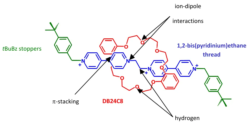
Some examples of this are shown in Figure 1-3. The second example, by Loeb and
Wisner, is similar to that of Stoddarts paraquat complex, with the
1,2-bis(pyridinium)ethane dication acting as the axle and dibenzo-24-crown-8 (DB24C8), a
smaller macrocycle then BPP34C10, as the wheel. The complex and all of its
non-covalent interactions are depicted in Figure 1-7, including the appropriately sized t-butyl
benzyl stopper groups.
Figure 1-7 – The Recognition motif by Loeb and Wisner
O N N N N O O O O O O O + +
+ O +
N N N N O O O O O O O + + + + DB24C8
tBuBz stoppers 1,2-bis(pyridinium)ethane
9
1.2 Molecular Switches based on MIMs
1.2.1 Molecular Machines
A machine is commonly referred to as a tool or device that performs a certain
action usually with the consumption of energy.10 Initial molecular machines were often
described as molecules, or a number of discrete molecular entities, that carry out a
function that is comparable to something that a machine would accomplish in the
macroscopic world. Some of the first molecular machines performed a function that
resembled that produced by pistons.
As defined by Leigh11, molecular machines consist of a functional molecular
system which is able to translate a controlled change in amplitude or directional of
mechanical motion of one component relative to another into some sort of useful work.
The motion can be the result of a covalent change (the breaking and forming of bonds) or
non-covalent change (breaking and forming of various non-covalent interactions),
however, for a fully functioning molecular machine, it must be able to return to its initial
state.
There are various types of mechanical motion, namely;
1. Brownian motion
2. Threading
3. Switching
4. Opening/Closing and Translocation
5. Circumrotational
10
7. Rotational
1.2.2 Brownian Motion
Brownian motion, otherwise known as spontaneous motion, is the random thermal
motion that every molecular-scale object undergoes. It is something that cannot be
avoided as it is a result of scale and not in any way due to the design of the system. As
long as there is some thermal energy (> 0K) in the system, it will undergo Brownian
motion.
Brownian motion can be dealt with in one of two different ways. Systems can be
designed that either utilize it or that fight against it. As of yet, any way of utilizing
Brownian motion in molecular machines has not been discovered. There are numerous
thought experiments that have been devised that utilize Brownian motion, such as
Maxwell’s Demon and Smoluchowski’s trapdoor, but there exists no known way of
actually creating them.11
1.2.3 Opening, Closing and Translocation
Opening, closing and translocation is a type of motion that involves structural
changes to the system that are usually extensively conformational in nature. These
changes can cause a molecule to open or close, effecting reactivity, or assist in
transporting molecules. The most common of this type of motion are classified as
allosteric systems12, tweezers13 and ion-transport channels14. Allosteric systems undergo
a conformational change when another molecule binds to them. This commonly occurs
11
The molecular system by Tobe15 and coworkers (Figure 1-8) displays this type of
motion. This molecule exists in an open or closed form which can be reversibly
interconverted through the use of light (open to closed) or heat (closed to open). The
main difference between these two forms is the size of the cavity, which impacts what
guest molecules can be bound in the macrocycle
O
O O O
O O O
O
O
O O
O O O O
O
hv
∆
Figure 1-8 – The open (left) and closed (right) forms of a molecular machine based on a crown ether ring.15
1.2.4 Threading and Dethreading
Threading occurs primarily in 11 upramolecular complexes called
pseudorotaxanes which was discussed in section 1.1.4.
1.2.5 Linear Motion – Shuttles
Molecular systems based upon linear movement are often called molecular
shuttles. The most common used when designing and synthesizing these systems are
rotaxanes. Rotaxanes, as discussed in section 1.1.5, consist of a linear axle with two
large stopper groups at each end which prevent the macrocycle from coming off. A
12
the macrocycle to bind to. The macrocycle, as shown in red in Figure 1-9, can bind to
either the light or dark blue recognition sites found on the axle.
Some of the simplest and earliest molecular shuttles consist of two recognition
sites where the macrocycle shuttles between the two states spontaneously, either due to
the use of similar recognition sites or a lack of an ability to control the shuttling process.
Since then, control has been added to many shuttles, usually either chemically,
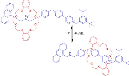
electrochemically or photochemically. Stoddart and coworkers have developed many
molecular shuttles, one of which is depicted in Figure 1-10. That system has two
different recognition sites, the 4,4’-bipyridnium site and the secondary ammonium ion
When acidified, the macrocycle, dibenzo-24-crown-8, preferentially rests over the
ammonium ion. When base is added, the ammonium ion is neutralized, the interactions
between the crown ether and the recognition site are reduced significantly, causing the
crown ether to now preferentially rest over the 4,4’-bipyridinium site. The addition of
acid causes the ammonium site to reform and the crown ether shuttles back to the
ammonium ion. The result is a reversible and controllable molecular shuttle.16
13
O
O O
O
H2+ N
N+
N+
O
O O
O O
O
H N
N+
N+
O
O O
O O
O
i-Pr2NEt H+
Figure 1-10 – A molecular shuttle designed by Stoddart and coworkers16
1.2.6Flip Switches
A flip-switch is a type of rotaxane that possesses two different states, similar to
that of shuttles, however, unlike shuttles, both states are around a single recognition site.
The two different conformations are shown in Figure 1-11. The macrocycle binds to the
yellow recognition site. The axle has two different stopper groups, depicted as green and
blue spheres. Similarly, the macrocycle possesses two different groups, one at each end,
depicted as green and blue discs. The system can exist in two different conformations,
one where the sphere and disc on the same side are similar in colour, and one where the
colours are different.
14
Work on these systems was done primarily by Loeb and coworkers.17 One of the
more recent examples is shown in Figure 1-12. The axle consists of a t-butyl benzyl
stopper on one side and a dimethyl benzoate on the other. The macrocycle,
dibenzo-24-crown-8, has been substituted on one side with two methoxy groups. This system
contains a charge transfer chromophore which produces unique colours for each state,
allowing for the determination of the ratio of conformers using UV-vis spectroscopy.
O
N+ N+
O O
O
O O
O O
N+ O
O OMe
OMe
N+ N+
N+ O
O
O O
O
O O
O MeO
MeO
Figure 1-12 – A flip-switch system developed by Loeb and coworkers 17
1.2.7Circumrotational Motion (Catenanes)
A catenane is a molecular system that consists of two or more macrocyclic
components which are held together mechanically and are unable to disassociate without
15
effect. One macrocycle is synthesized around the other in a manner similar to clipping
for rotaxane synthesis.
In order for a catenane to behave as a molecular machine, one of the macrocycles
must contain at least two different recognition sites. Also, it must be switchable in a
controlled and reversible manner, as depicted in Figure 1-13.18
Figure 1-13 – An illustrated example of a [2]catenane capable of molecular motion
1.2.8Rotary motion
Artificial molecular rotors are capable of undergoing unidirectional 360o rotary
motion repetitively under the influence of an external stimulus. The design and synthesis
of these types of systems is extremely difficult and challenging. Currently, most artificial
rotors are designed around the rotation about a sterically hindered carbon-carbon double
bond which can be controlled through light induced rotation.
Of these systems, the most notable examples were developed by Feringa and
coworkers. His system possesses an overcrowded alkene, which results in a helical
arrangement between the rings. Upon exposure to light (above 280 nm) it undergoes a
180o rotation about the double bond. With the addition of thermal energy, a helical
inversion occurs which allows for a continued rotation to occur. Upon exposure to light
and sufficient thermal energy for the helical inversions to occur, the system will undergo
16 >280nm
∆ (20oC) ∆ (60oC)
>280nm
17
1.3 Thin Films and Self Assembled Monolayers
1.3.1 Langmuir-Blodgett films
One of the earliest thin films that was discovered and well studied is known as a
Langmuir-Blodgett (LB) film. Langmuir completed the first systematic studies of
monolayers on the interface, focusing on the air-water interface.20 Blodgett studied the
deposition of said monolayers on a solid substrate.20 In the LB technique, a molecular
film is compressed in order to achieve a densely packed monolayer at the air-water
interface. The monolayer is then physisorbed on a solid substrate using the displacement
of a vertical plate, a process known as vertical deposition. This process can be performed
at very high deposition rates. While effective, LB films have a few drawbacks. Very
specific conditions are required for the film to form and the monolayer is merely
physisorbed to the solid substrate, so desorption is a strong possibility.20
1.3.2 Self-Assembled Monolayers
Self-assembled monolayers (SAMs) are thin films that are formed spontaneously
upon immersion of a substrate into a solution of the desired components. SAMs, unlike
LB films, are chemisorbed to the surface, through either covalent or ionic bonds. Some
of the first self-assembled monolayers were created by Zisman et al. They exposed a
glass surface to hexadecanol and found that it formed monolayer films with wetting
properties resembling those of Langmuir Blodgett films.21
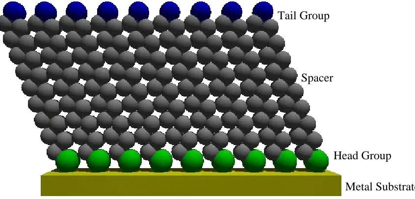
A self-assembled monolayer consists of four basic components, shown in Figure
1-15. The first component is the substrate. This is the surface that the monolayer binds
18
shown in green, serves as the binding agent between the monolayer and the substrate.
This normally consists of a strong bond such as Si-O or S-Metal bond. The spacer group,
shown in gray, separates the head group from any functional groups of interest, usually
found in the tail group, helping to prevent any unwanted interactions between the tail
group and the substrate. Its other main purpose is to provide stabilizing interactions
between the molecules, which lowers the overall energy of the system, promoting
monolayer formation. This is usually accomplished through the use of alkane chains
which have the potential for numerous Van der Waals interactions. The final component
is the tail group. It is this group which defines the physical properties of the surface and
determines its reactive properties as well.
Figure 1-15 An illustrated example of a well packed SAM
1.3.3 Alkyl Silane Self-Assembled Monolayers
Some of the earliest SAMs discovered were formed using a silicon dioxide
substrate. Alkyl silane SAMs are formed by taking a hydroxylated surface substrate
(usually a silicon wafer) and exposing it to a solution of an alkyltrichlorosilane. The Tail Group
Spacer
Head Group
19
trichlorosilane reacts with the hydroxyl groups to form covalent Si-O bonds with the
substrate. It also reacts with any trace water that is present to form Si-O-Si connections
between the molecules. As a result of this, the monolayer can be considered as a
polysiloxane layer cross-linked along the substrate. This makes the monolayer very
stable and able to be exposed to most organic solvents (aside from basic media). The
major downside to these SAMs is their reproducibility. There is a lot of inconsistency
from sample to sample since the trace amount of water present is difficult to keep
consistent and aggregation of the silanes prior to SAM formation can occur. This is less
of an issue in industry where the monolayer does not need to be completely uniform as
long as it performs the desired function. When studied in a laboratory setting, lack of
reproducibility makes characterization difficult to accomplish. 20
1.3.4 Thiol Self-Assembled Monolayers
The thiol moiety is capable of forming strong covalent bonds with various metals.
The most commonly used are Au, Ag, and Cu.20 When alkanethiols are exposed to a
metal surface, it is this strong covalent interaction that promotes the formation of a SAM
that is not only stable, but is also usually densely packed and uniformly oriented. SAMs
formed with thiols do not suffer with as many issues as the siloxane SAMs do. The
major advantages are that they are reproducible and have a larger variety of functional
groups that they are compatible with.
1.3.5 The Gold Surface
As mentioned, thiols can form SAMs with various metal substrates. However,
20
tolerance for various tail groups. Of all of the surfaces that are used to make SAMs with
alkanethiols, the most commonly used metal is gold. The main reason for this is that gold
is easy to use as a substrate. It forms a very strong bond with sulphur (45 kcal/mol)22
and, as a metal, gold is relatively inert, making it ideal for use under ambient conditions.
It will not form an oxide layer and most contaminants are easily displaced by incoming
thiols. As a result, SAMs on gold can be formed taking very few extra precautions
beforehand.
Gold surfaces for SAMs can be formed using gold foil, physical vapour
deposition, electrodeposition, or electroless deposition23. Of those, the most common
method used to form the gold surface is physical vapour deposition, which is evaporation
of the gold using an electric current, followed by deposition of the evaporated gold onto
the desired substrate. It is generally done under an ultra-high vacuum (< 10-5 Torr) where
a current heats up the gold sample to the point of evaporation. The current is applied by
either applying a voltage across a tungsten filament that is supporting the gold or by
shooting an electron beam directly at the gold. Physical vapour deposition is
advantageous because it is a relatively cheap process, excluding the initial cost for the
equipment itself, and it forms extremely pure surfaces.
The gold is commonly evaporated onto glass slides, silicon wafers, or mica.
However, gold does not inherently bind to these materials, so an interim layer is required.
A thin layer (1-10 nm) of either chromium or titanium is used to hold these two materials
together.
Gold surfaces formed through evaporation have a polycrystalline structure with a
21
of approximately 3 nm between the grains as determined through atomic force
microscopy (AFM).24
1.3.6 SAM Formations – Kinetics and Thermodynamics
The main thermodynamic factors that affect the formation of SAMs can be broken
down into several components:
• The thiol interaction with the metal surface
• The Van der Waal interaction between the spacer groups
• Interactions between the tail groups of adjacent adsorbents
The different regions of the monolayer are in competition to form the most stable
macroscopic organization of the SAM. Most commonly, it is the thiol-metal interaction
that heavily determines the organization, however, depending on the design of the
adsorbate, other interactions can take priority.20
In terms of kinetics, SAM formation consists of two basic steps:
• Formation of the Au-S bond
• ‘Annealing’ of the aliphatic chain
The formation of the Au-S bond is generally considered to be the faster step in the
formation process. It has been shown using quartz crystal microscopy that for various
alkanethiols the formation of the Au-S bonds in a SAM are complete mere minutes after
the substrate was immersed in a solution of the thiol.20
The second step, which is often called annealing, is most often the limiting step.
It is in this step that the alkane chains reorganize into the most stable form, where the
alkyl chain is predominately trans extended and tilted relative to the gold surface. The
22
several days.25 The design of the head and tails groups, as well as the length of the
spacer group all significantly impact this process.
1.3.7 SAM Structure
Alkanethiols form a densely packed crystalline monolayer with a homogenous
interfacial layer at the surface. On Au(111), the sulphur adopts a (√3x√3)R30o
configuration as defined using Woods notation with an inter-chain spacing of 5Å,
depicted in Figure 1-16. Five angstroms is too far apart to provide and stabilizing
interactions between the alkyl chains. As a result, the alkyl chains tilt relative to the
surface, reducing the average distance between the chains.
a) b)
Figure 1-16 An illustration of a) the surface structure of Au(111) and b) the packing of thiols, shown in red, onto a Au(111)surface
The length of the alkane plays a strong role in the overall arrangement of the
SAM. A long chained alkanethiol will usually be all trans extended with a 30o tilt angle
and a relative homogeneous surface. Shorter chains (n<11) are more disordered, with a
larger number of gauche conformers. As a result, the SAM is not as well packed and this
results in a SAM that is less crystalline and more liquid-like with fewer tail groups
23
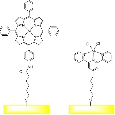
1.3.8 Bulky Tail Groups
Often, tail groups with a more complex structure are used when forming SAMs.
These larger tail groups are of interest because they provide excellent sites for further
reactivity after the SAM has been formed. Any sites with a size comparable or smaller to
that of a single 6-membered ring are not likely to affect packing since that is comparable
to that of the size of the polymethylene chain itself. Anything larger than that will begin
to sterically hinder any dense packing. This results in a disordered, liquid-like
hydrocarbon region.26
Various different large tail groups have been used in SAM synthesis, two
examples of which are shown in Figure 1-17. The first example27 consists of a porphyrin
ring connected to gold via an alkanethiol. It can act as an electrocatalytic monolayer that
has the potential to reduce various systems. The second example28 is terminated in a
terpyridine. The presence of the terpyridine group allows for preparation of redox active
metallic systems that can sequentially self assemble.
S NH
N N N
N M
O
S N
N N M
Cl Cl
24
1.4 Controlling Surface Properties
1.4.1 Introduction
Molecular machines, as mentioned earlier, are systems which, through a
controlled change produce, work. A large portion of the attempts at molecular machines
have currently been designed and synthesized to function in solution. While molecular
machines in solution are generally the easiest to synthesize and study, their value is
limited. In solution, the individual molecular machines are randomly distributed
throughout and as a result, on average, any work gained from one machine is cancelled
out from work in the opposite direction produced by other machines. In order to prevent
that from occurring, an additional element of order needs to be added to the system.
There are several different ways that that can be accomplished. Three
dimensional ordered systems are generally produced through the formation of
frameworks, such as metal organic frameworks (MOFs) or with SAMs formed on
nanoparticles. Two dimensional ordered systems are formed by forming SAMs on 2D
substrates, as described previously.
The following sections describe some of the most notable attempts at molecular
machines synthesized to date.
1.4.2 Rotary motion
In terms of molecular machines involving rotary motion, some of the most
advanced so far have been characterized by Tour29 and Feringa30. Tour and coworkers
have developed azimuthal rotors with the design shown in Figure 1-18a. The rotor
25
field, the molecule rotates about the triple bond indicated. Feringa and coworkers have
synthesized numerous molecular rotors, all based of the sterically hindered double bonds
as shown in Figure 1-14. The design has been adapted for SAMs, forming monolayers of
both azimuthal28 and altitudinal28 (Figure 1-18b) rotors. By controlling the rotation of the
rotor, it is possible to control which end of the rotor is facing towards the surface. When
the substituted end (R = C4F9) is towards the surface, an increase in the contact angle
(from 80o to 92o) with water was seen.
R
O O
O O
N N N
N N N
Si O Si O O
N
Me2N NO2
Si
S Au S
Au
S Au
a) b)
Figure 1-18 – Molecular Rotors formed on a 2D substrate developed by a) Tour and b) Feringa
1.4.3 Shuttling
Leigh and coworkers31 attached a [2]rotaxane shuttle onto a SAM of
mercaptoundecanoic acid through interactions between the acid group and nitrogen on
the aromatic ring, as seen in (Figure 1-19). Upon exposure to ultraviolet light, the axle
undergoes a cis-trans isomerization and the macrocycle shuttles from the green to orange
26
surface from seeing the fluorine groups, changing the hydrophilicity of the surface. A
drop of water placed on top can effectively be moved along the surface. This was
accomplished by exposing a nearby area to UV light and triggering the shuttling process.
The drop will move, depending on where the SAM was exposed to UV light. The effect
is even strong enough to move a drop of water against an incline.
S HO O S HO O S HO O S HO O S HO O S HO O F F S HO O S HO O S HO O S HO O S HO O S HO O F F UV Light
Figure 1-19 – a) The molecular shuttle system by Leigh and coworkers which shuttles upon exposure of the SAM to UV light31
Stoddart and coworkers have developed several molecular machines based on the
shuttling between the two sites shown in Figure 1-20. By exposing the system to the
appropriate redox conditions, the system can be controllably shuttled between the two
states. Using this concept, molecular machines, such as a molecular muscle32, bistable
switch tunnel junction33, nanowire34, and a molecular valve35 have all been synthesized
and studied. It has even been used as a data storage device, storing up to 160 kbit of data
27
S
S
O O O R
N+
N+ O
O O
S
S S
S
O O O R
O O O R'
O O O R'
N+
N+
N+
N+ N+
N+
O O O
S
S
Oxidation Reduction
![Figure 1-5 – An illustrated example of the three synthetic routes for [2]rotaxane formation](https://thumb-us.123doks.com/thumbv2/123dok_us/1406603.1173282/34.612.117.516.431.669/figure-illustrated-example-synthetic-routes-rotaxane-formation.webp)


![Figure 1-13 – An illustrated example of a [2]catenane capable of molecular motion](https://thumb-us.123doks.com/thumbv2/123dok_us/1406603.1173282/43.612.114.523.220.309/figure-an-illustrated-example-catenane-capable-molecular-motion.webp)