Vehicle Theft Detection and Prevention Using
GSM and GPS
Champa Bhagavathi.R1, Gowri.B.R2, Kasturi.R3, Pooja.C4
Student, Dept. of CSE, The National Institute of Engineering, Mysuru, Karnataka, India1
Student, Dept. of CSE, The National Institute of Engineering, Mysuru, Karnataka, India2
Student, Dept. of CSE, The National Institute of Engineering, Mysuru, Karnataka, India3
Student, Dept. of CSE, The National Institute of Engineering, Mysuru, Karnataka, India4
ABSTRACT: This paper presents a mechanism to make vehicle thefts almost impossible. GSM and GPS technologies
are used for that purpose. The proposed system provides two levels of security, password protection for the vehicle and remote ignition cut-off mechanism. This system also provides provision for vehicle tracking using GPS. GSM technology is used for intimating the owner. An alert message is sent to the owner if the wrong password is entered. Message is also sent when the ignition system of the vehicle is started. The owner can respond with an SMS to stop the engine. A buzzer is also activated to alert the nearby people or the security personnel if the right password is not entered after maximum number of trials. Message is sent to owner even when vehicle is started using correct password.
KEYWORDS: GSM, GPS, password, Ignition cut-off, buzzer.
I. INTRODUCTION
In today’s world almost every common man owns a vehicle. Vehicle theft is a common issue which everyone faces in insecure parking places. This is a major problem which seemingly little being done about it. Several underlying problems have led to increase in vehicle theft, ranging from sheer human absent mindedness, to the lack of vehicle parking structures. The safety of the public vehicle is extremely essential. Current security systems have certain vulnerabilities.
GSM and GPS technologies are employed to make vehicle theft almost impossible. Global System of mobile communication is a globally accepted standard for digital cellular communication. Owner of the vehicle uses Subscriber Identity Module (SIM) inserted within his cell phone to send messages to GSM modem which is a part of vehicle theft prevention system that is attached to vehicle. A GSM modem is a specialized type of modem which accepts a SIM card, and operates over a subscription to a mobile operator, just like a mobile phone. From the mobile operator perspective, a GSM modem looks just like a mobile phone.
GPS technology is used for tracking vehicle. The Global Positioning System (GPS) is a
space-based navigation system that provides location and time information in all weather conditions, anywhere on or near the Earth where there is an unobstructed line of sight to four or more GPS satellites.
II.RELATEDWORK
In [1], the owner sends a message to the central controller system in case of vehicle theft. The central controller system sends signals to the security system installed in the vehicle that stops or locks the engine immediately. The vehicle is brought to the normal condition upon entering a password.
The weakness in [1] is that it relies on the central controller system to take necessary actions in case of theft. The vehicle is not stopped immediately as it takes time for information to pass from owner to central system and then to the security system. There is no confidentiality of password as it is known to the central system which may be misused.
In [2], Advanced RISC Machine processor and face recognition system is used as a means of authentication. The owner is notified using MMS with the help of GSM/GPRS when an attempt is made to steal the vehicle.
The weakness in [2] is that it uses face recognition for authentication which means only one user will be considered as authorized to drive the vehicle or multiple face recognition system must be used.
In [3], IR sensors send message to controller. Car location information is sent to owner. The engine is stopped and doors are locked automatically if the theft is detected. A password has to be entered to unlock the doors and switch on the engine to bring the car to normal condition.
The weakness in [3] is that the system uses IR sensors. They are incapable of distinguishing between objects that irradiate similar thermal energy levels. Infrared detectors are also rather expensive, so they are not as widely used as they could be.
In [4], password or fingerprint is used for authentication. GSM and GPS are used for notifying the owner and providing location information. Car engine can be turned off if theft is detected. In case of accident, engine is turned off and doors are opened.
The weakness in [4] is that the system is vulnerable to password hacking and it uses fingerprint for authentication. This limits the ownership of car to one person.
In [5], keyless access is provided to vehicle using a password. High security is provided by an alarm system which is triggered when number of incorrect entries exceeds the set limit. Additional security measures include a GSM Module which alerts the owner through SMS in case of a theft attempt.
The weakness in [5] is that the system is vulnerable to password hacking. If the thief is able to enter the right password, then, the system fails to prevent vehicle theft.
In [6], three stages of protection are used to strengthen the security of the car. If wrong password is entered, the power will remain disabled. Disabling the starter motor from being turned on in case the power is shifted by others. Directional valve is set so that engine is not turned on if unauthorized person connects the starter motor directly to the car battery.
System in [6] is a very good model for ensuring safety in cars. But this system is specific to cars. The system is vulnerable to password hacking.
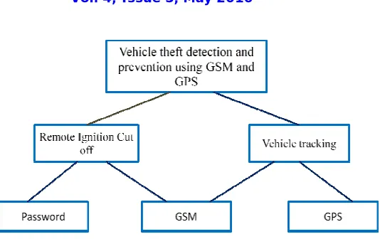
III.PROPOSEDSYSTEM
Figure 1: Architectural diagram
Steps explaining detailed functioning of the system are as follows. 1. Initialize I/O devices.
2. Initialize UART1 & UART2.
3. Enable reception interrupt for UART2.
4. Check for the presence of SIM in GSM modem.
5. Configure GSM modem using AT commands.
6. Read OTP from memory location.
7. Perform mathematical calculations which result in generation of OTP.
8. Send OTP message to the user.
9. Initiate keypad operation.
10. Read key and compare them with stored OTP.
11. Repeat above step for all four keys pressed.
12. Repeat the above two steps for three trails if wrong password is being entered.
13. Lock keypad. Turn ON buzzer. Send message to owner after three wrong password entry attempts.
14. If the entered password is correct, initiate GPS operation.
15. Extract Longitude and latitude from information received by GPS receiver.
16. Read GSM message.
17. If message is $LOC, send location co-ordinates to corresponding mobile.
18. If message is $OFF, turn ON buzzer and send message to owner about location of the vehicle.
IV.PROPOSEDSYSTEMDESIGN
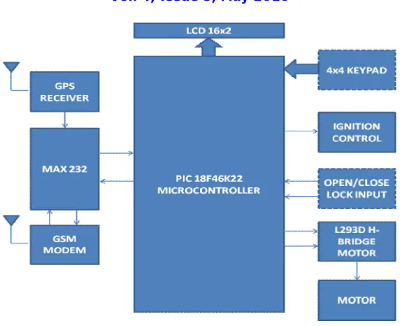
A. Block Diagram
Figure 2: Block diagram
B. Brief description of hardware
Microcontroller PIC18F46K22: It is the heart and core of the system to which all the other components are interfaced. PIC is a family of RISC microcontrollers made by Microchip Technology, PIC18F4520. It is a 40 pin Low-Power, High-Performance Microcontroller with XLP Technology.
Power supply: 7805 is a voltage regulator integrated circuit. It is a member of 7805 series of fixed linear voltage regulator ICs. The voltage source in a circuit may have fluctuations and would not give the fixed voltage output. The voltage regulator IC maintains the output voltage at a constant value. 7805 provides +5V regulated power supply. Capacitors of suitable values can be connected at input and output pins depending upon the respective voltage levels.
LCD interfacing: It is the display unit of the system that displays appropriate messages based on the scenario. The most commonly used Character based LCDs are based on Hitachi's HD44780 controller or other which are compatible with HD44580. LCD consists of LCD driver/controller that is used to interface LCD and microcontroller.
GPS Receiver: The GPS is used to obtain the current location of the vehicle. The Global Positioning System (GPS) is a satellite-based navigation system consists of a network of 24 satellites located into orbit. Information from the GPS system is accessible with GPS receiver. GPS receiver is used to detect the vehicle location and provide information to responsible person through GSM technology. GPS unit can determine other information like, speed, distance to destination, time etc once the vehicle position has been determined.
L293D H Bridge motor: It is a monolithic integrated, high voltage, high current, 4-channel driver. The H-Bridge is typically an electrical circuit that enables a voltage to be applied across a load in either direction to an output, e.g. motor.
Motor: It is the DC motor that represents the engine. DC motor is interfaced with microcontroller. Speed, direction of rotation of motor etc can be controlled by interfacing with the microcontroller.
C. Software Interfaces
MPLAB IDE v8.92: MPLAB IDE is a software program that runs on a PC to develop applications for Microchip microcontrollers. MPLAB IDE technology custom built by Microchip Technology in Microsoft Visual C++. MPLAB supports project management, editing, debugging and programming of Microchip 8-bit, 16-bit and 32-bit PIC microcontrollers.
Hi-Tech C Compiler: HI-TECH C Compiler for PIC18MCUs standard fully implements the optimizations of
Omniscient Code Generation, a whole program compilation technology to provide denser code and better performance on PIC MCUs.
Proteus 7.0: Proteus 7.0 is a Virtual System Modelling (VSM) that combines circuit simulation, animated components
and microprocessor models to co-simulate the complete microcontroller based designs. This is the perfect tool for engineers to test their microcontroller designs before constructing a physical prototype in real time. This program allows users to interact with the design using on-screen indicators and/or LED and LCD displays and, if attached to the PC, switches and buttons.
Diptrace: PCB Layout provides PCB designs with an easy-to-use manual routing tools, shape-based auto router and
auto-placer. Schematic feature provides Schematic Capture with multi-level hierarchy and export to PCB Layout, Spice or Net list. Component and Pattern Editors allows making new parts and footprints. Standard Libraries include 100,000+ parts. Import/Export Features allows exchanging designs and libraries with other EDA tools.
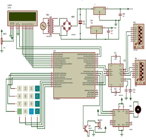
D. Circuit design
The circuit contains various hardwares that are interfaced with the microcontroller. The hardware components include capacitors, rectifiers, GPS receiver, GSM modem, voltage regulators, buzzer, dc motor, motor driver, LCD unit, keypad, max 232. The system is operated using +5V dc power supply.
PIC18F46K22 microcontroller is the heart and core of the system to which all the other components are interfaced.
LCD is the display unit of the system.L293D H Bridge motor is a monolithic integrated, high voltage, high current, 4-channel driver. DC Motor represents engine of the vehicle.
Figure 3: Circuit diagram
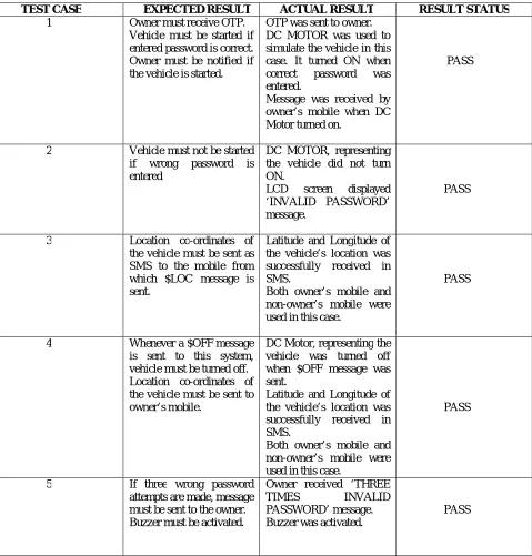
V. RESULTS
TEST CASE EXPECTED RESULT ACTUAL RESULT RESULT STATUS
1 Owner must receive OTP.
Vehicle must be started if entered password is correct. Owner must be notified if the vehicle is started.
OTP was sent to owner. DC MOTOR was used to simulate the vehicle in this case. It turned ON when
correct password was
entered.
Message was received by owner’s mobile when DC Motor turned on.
PASS
2 Vehicle must not be started
if wrong password is
entered
DC MOTOR, representing the vehicle did not turn ON.
LCD screen displayed
‘INVALID PASSWORD’ message.
PASS
3 Location co-ordinates of
the vehicle must be sent as SMS to the mobile from which $LOC message is sent.
Latitude and Longitude of the vehicle’s location was successfully received in SMS.
Both owner’s mobile and non-owner’s mobile were used in this case.
PASS
4 Whenever a $OFF message
is sent to this system, vehicle must be turned off. Location co-ordinates of the vehicle must be sent to owner’s mobile.
DC Motor, representing the vehicle was turned off when $OFF message was sent.
Latitude and Longitude of the vehicle’s location was successfully received in SMS.
Both owner’s mobile and non-owner’s mobile were used in this case.
PASS
5 If three wrong password
attempts are made, message must be sent to the owner. Buzzer must be activated.
Owner received ‘THREE
TIMES INVALID
PASSWORD’ message. Buzzer was activated.
PASS
VI.CONCLUSIONANDFUTUREWORK
The implementation of Vehicle theft detection with high level authentication is done successfully. A Vehicle Positioning System is thus designed by using PIC18F46K22 controller along with GPS, GSM and password modules. When the latitude and longitude values obtained and fed into Google Earth software, the location of the vehicle could be found out. Authentication is also provided so that only the authorized users can access the vehicle. The use of One Time Password makes it almost impossible for the thief to hack the password. A wide future scope guarantees that an enhancement to this system finds a great importance in real time system.
The model can be implemented in bikes with adjustments made to spark plug, battery and key. The system can further be improved with speed control mechanism, that is, to stop the engine if the speed exceeds certain limits. The system can further be improved for providing parental guidance that is to stop the vehicle if it crosses a certain range of distance.
REFERENCES
[1] Nagaraja, B.G.; Rayappa, R.; Mahesh, M.; Patil, C.M. and more authors, “Design & Development of a GSM Based Vehicle Theft Control System”, International Conference on Advanced Computer Control, 2009. ICACC ‘09, Page(s):148 - 152, 2009.
[2] D.Narendar Singh, K.Tejaswi (M.Tech), “Real Time Vehicle Theft Identity and Control System Based on ARM 9”, International Journal of Latest Trends in Engineering and Technology (IJLTET), Vol. 2 , Issue-1 January 2013, Page(s): 240-245, 2013.
[3] R.Ramani, S.Valarmathy, Dr. N.SuthanthiraVanitha, S Selvaraju, R Thangam, M Thiruppathi, “Vehicle tracking and locking system based on GSM and GPS”, I.J. Intelligent Systems and Applications, Vol. 5, Issue-9 August 2013, Page(s): 86-93, 2013.
[4] Amaradi Kondababu, N.V.Satish, “Vehicle Anti Theft System and Emergency Accident Notification and Rescue System using ARM”, International Journal of Scientific Engineering and Technology Research, ISSN 2319-8885 Vol.03,Issue.37 November-2014, Page(s):7574-7580,2014.
[5] Vipin Venugopal, Haritha Chandrasekhar, Krishna Nilayangode, “Password Protected Vehicle Access System”, International Journal of Innovative Science and Modern Engineering (IJISME) ISSN: 2319-6386, Volume-2, Issue-11 October 2014, 2014.
[6] Mohammed Abuzalata, Muntaser Momani, Sayel Fayyad and Suleiman Abu-Ein, “A practical design of anti-theft car protection system based on microcontroller”, American Journal of Applied Sciences 9 (5): ISSN 1546-9239, Page(s):709-716, 2012.
BIOGRAPHY
Champa Bhagavathi R is pursuing her Bachelor of Engineering degree in the department of Computer Science and
Engineering, The National Institute of Engineering, Mysuru, Karnataka, India.
Gowri B R is pursuing her Bachelor of Engineering degree in the department of Computer Science and Engineering,
The National Institute of Engineering, Mysuru, Karnataka, India.
Kasturi R is pursuing her Bachelor of Engineering degree in the department of Computer Science and Engineering,
The National Institute of Engineering, Mysuru, Karnataka, India.
Pooja C is pursuing her Bachelor of Engineering degree in the department of Computer Science and Engineering, The