Interference Aware Admission Control Using
Available Bandwidth
Rohini Mohan M
M. Tech Student (Communication Engineering), Dept of ECE, IIET, M.G. University, Kottayam, Kerala, India.
ABSTRACT: A WMN is dynamically self-organised and selfconfigured, with the nodes automatically establishing and
maintaining mesh connectivity. In WMNs, admission control is deployed to efficiently control different traffic loads and prevent from overloaded network. Due to recent advances in wireless technologies, wireless mesh networks (WMNs) are expected in the near future to fully handle content-rich multimedia services with various quality of services (QoS) guarantee. In this paper a data and control plane based Rate Adaptive Routing on Cliques Admission Control protocol or extended RA-RCAC (so-called ERA-RCAC) for WMNs is proposed, which is able to provide feedbacks to the application layer whenever congestion occurs in the network. By using data plane method in RA-RCAC technique the performance can be increased. The throughput and packet delivery ratio can be increased. The delay and packet loss can be reduced to some extent. Data plane forwards packets along the minimum cost routes in a best-effort manner, but tries hard not to drop packets.
KEYWORDS: Wireless Mesh Networks ,Clique Heads, Quality Of Service,
I. INTRODUCTION
Wireless mesh networks (WMNs) have gradually replaced wired networks due to its high transmission rate, low deployment cost, and extensive signal coverage. Their self-organized and self-configured features can greatly help in providing and maintaining connectivity among communities. WMNs are composed of mesh clients (MCs) and mesh routers (MRs), each of which communicates with one another by multi hop relays. The MRs are connected to the external wired networks through Internet gateways (IGWs), and each node in WMNs can act as either an MR or an MC. However, despite those great features, the provision of multimedia communications over WMNs requires that stringent quality of services (QoS) constraints be achieved compared with best effort data applications such as e-mail, www, and ftp, where packet delay and jitter have a lower impact. Thus, facilitating the handling of QoS requirements in order to provide admission control for multimedia traffic in the presence of data traffic becomes a very challenging problem over a WMN because of the available limited bandwidth .
Most of the protocols so far that deal with this issue strictly operate within their own layer In order to provide the required QoS guarantees, a protocol design is needed, which involves the cooperation of different layers. In this paper, a data plane and control plane based distributed admission control protocol for WMNs [called Rate Adaptive Routing on Cliques Admission Control (ERA-RCAC)] is proposed, which is suitable for multimedia environment and which can provide explicit QoS support in WMNs. The RA-RCAC approach adopts a crossl ayer design while taking advantage of the design features of both the Interference-Aware Admission Control (IAAC) and the Routing on Cliques Admission Control (RCAC).
II. RELATEDWORK
route discovery process. It directs routing message propagations and avoids “hot-spots” with severe interference. In [2] proposed an integrated admission control and routing mechanism for multi-rate wireless mesh networks.Admission control depends on precise estimates of available bandwidth at involved nodes and the bandwidth consumption required by a new flow. Estimating these parameters in wireless networks is challenging due to the shared and open nature of the wireless channel. Existing available bandwidth estimation techniques do not accurately consider interference from neighboring nodes and flow bandwidth requirementestimates or act overly conservative, restricting opportunities for parallel transmission due to spatial reuse. They propose the DCSPTmethod for available bandwidth estimation, based on dual carrier sensing with parallel transmission awareness. Here also introduce apacket probing-based available bandwidth estimation method, suitable for legacy device implementations, and verify it experimentally. These techniques are integrated in an admission control mechanism designed for a hop-by-hop routing protocol (LUNAR), enabling alternate route identification when shortest paths are congested. In [3] proposed a data plane mechanism for ensuring connectivity. A network architectures having two basic components: a data plane responsible for forwarding packets at line-speed, and a control plane that instantiates the forwarding state the data plane needs. With this separation of concerns, ensuring connectivity is the responsibility of the control plane. However, the control plane typically operates at timescales several orders of magnitude slower than the data plane, which means that failure recovery will always be slow compared to data plane forwarding rates. In this paper they propose moving the responsibility for connectivity to the data plane. Our design, called Data- Driven Connectivity (DDC) ensures routing connectivity via data plane mechanisms. We believe this new separation of concerns basic connectivity on the data plane, optimal paths on the control plan will allow networks to provide a much higher degree of availability, while still providing flexible routing control. In [4] In WMNs, admission control is deployed to efficiently control different traffic loads and prevent the network from the overload. Admission control is one of the mechanisms that must be deployed to provide the QOS. An admission of new user is accepted if sufficient resources are available. They propose a distributed admission control mechanism for WMNs, routing cliques admission control (RCAC). RCAC accepts the clique (user) request while predefined the thresholds of packet loss probability and end-to-end delay satisfying. This mechanism helps to avoid the congestion. In RCAC consider two QOS parameters in WMNs: 1) packet loss 2) end-to-end delay in multichannel and multi radio WMNs. In [5] proposed a robust and efficient collection through control plane and data plane integration.Despite being a core networking primitive, collection protocols today often suffer from poor reliability (e.g., 70%) in practice, and heavily used protocols have never been evaluated in terms of communication efficiency. Using detailed experimental studies, we describe three challenges that cause existing collection protocols to have poor reliability and waste energy: inaccuracies in link estimation, link dynamics, and transient loops. In this paper we present CTP, a robust, efficient, and hardware-independent collection protocol. CTP uses three novel techniques to address these challenges. CTP’s link estimator addresses the inaccuracies in link estimation by using feedback from both the data and control planes, using information from multiple layers through narrow, platform independent interfaces. Second, CTP addresses link dynamics by using the Trickle algorithm for control traffic, sending few beacons in stable topologies yet quickly adapting to changes. Finally, CTP addresses transient loops by using data traffic as active topology probes, quickly discovering and fixing routing failures.
III. PROPOSEDMETHOD
The proposed RA-RCAC scheme has the following design features.
1) It models the interconnected clique heads (CHs) as a queuing network and approximates the packet loss probability with the overflow probability in each clique.
2) It uses the conflict graph model introduced in to model the interference in WMNs. In this case, nodes exchange their flow information periodically and compute their available bandwidth based on local maximal clique constraints. 3) It uses the distributed admission control technique introduced in to achieve some scalability by partitioning the network into cliques; only CHs are involved in the admission control procedure. It accepts new incoming flows only when the network target loss rate and the end to- end delay are satisfied and maintains relatively high resource utilization.
4) It includes an on-demand routing scheme that explicitly incorporates an interference model (both inter- and intraflow interference) in its route discovery process, which directs the routing message propagations while avoiding hot spots with severe interference.
RA-RCAC is a reactive approach since it creates the routes only when desired by the source node. When a node requires a route to a destination, it initiates a route discovery process within the network. This process is completed once a route is found or all possible route permutations have been examined. For the design of RA-RCAC, the following assumptions prevail:
1) the assignment of channels is static;
2) network failures (i.e., link or node failure) are not considered; 3) new flows arriving in each A-clique are uniform and independent.
In our design, only CHs are involved in admission control instead of the complete set of nodes. This technique helps in reducing the number of control packets since a lesser number of nodes are involved in admission control and, thus, in the routing process. It lessens the probability of congestion in the network as only those nodes that satisfy the minimum bandwidth criteria depending on the bandwidth of the message to be transmitted are processed. It also leads to efficient usage of the routing table space as only those routes that are obtained through our scheme are stored.
In RA-RCAC, we have also classified multimedia data flows into two groups: critical ones when the multimedia traffic information is deemed critical/important to the application in need of it and noncritical ones when the existence of such information is not critical to the application in need of it. Therefore, it may be terminated if required to free the network resources for more critical operations This distinction is implemented in the RA-RCAC scheme by giving the route requests generated for transmitting critical information a higher priority and providing a rate adaptive admission control during the route discovery process.
(A)DATA PLANE AND CONTROL PLANE METHOD
The control plane is responsible for estimating the quality of links between neighbors, and for forming a topology and selecting routes. Protocols do this by using periodic control packets. The data plane then uses these links and routes to send and forward packets. The data plane is responsible for forwarding packets towards one of the base stations, along the paths defined by the control plane. CTP forwards packets along the minimum cost routes in a best-effort manner, but tries hard not to drop packets. While an end-to-end protocol is needed to achieve 100% reliability, CTP routinely achieves 99.9% reliability in our experiments. To this end the data plane provides invaluable information, at forwarding time, to aid in route repair and in link estimation. Packets being forwarded can be uniquely idenfied by the origin, origin-generated sequence number, and number of hops traversed. With these fields the data plane can detect and remove duplicate transmissions. Packets also carry the smallest cost they have seen to the root, and if this happens to be smaller than the current node’s cost, a routing inconsistency is detected. This event immediately triggers the control plane to update its routing topology among the neighbors. Finally, information about the number of retransmissions of a packet directly feeds the hybrid link estimation, again ensuring a more timely and accurate estimate.
Fig:4.1: Network architecture of data plane and control plane
destination(s) that have sufficient resources to support the requested QoS. At each network node, call admission control decides whether a connection request should be accepted or rejected, based on the requested QoS, the wired link status, and/or the statistics of wireless channels. For base stations, wireless channel characterization is needed to specify the statistical QoS measure of a wireless channel, e.g., a data rate, delay bound, and delay-bound violation probability triplet; this information is used by call admission control.
If a connection request is accepted, resource reservation at each networknode allots resources such as wireless channels, bandwidth, and buffers that are required to satisfy the QoS guarantees. During the connection life time, packet scheduling at each network node schedules packets to be transmitted according to the QoS requirements of the connections. As shown in Figure 1, in a network node, QoS routing, call admission control, resource allocation, and wireless channel characterization, are functions on the control plane, i.e., performed to set up connections; packet scheduling is a function on the data plane, i.e., performed to transmit packets.
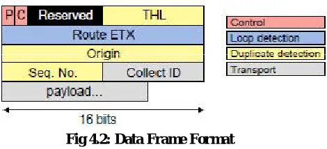
(B) DATA FRAME FORMAT
Fig 4.2: Data Frame Format
Figure 4.2 shows a CTP data frame, which is eight bytes long. The data frame shares two fields with the routing frame, the control field and the route ETX field. The C bit operates independently for the two packet types. When the forwarding queue fills up and a node drops a packet, it must set the C bit on the next routing frame and the next data frame, allowing the datapath to quickly pass congestion information up the routing tree without requiring a routing frame. Like the routing frame, the route ETX field of a data frame is fixed point decimal with a range of 0−655.35. A data frame has an origin address and an 8-bit origin sequence number, which identify unique packets generated by an endpoint. In addition, the dataframe has an 8-bit time has lived, or THL field. This field is the opposite of a TTL: it starts at zero at an end point and each hop increments it by one. The three foregoing fields constitute the packet signature. CTP uses this signature to determine if a packet is a duplicate so that the duplicates can be discarded. Finally, a CTP data frame has a one-byte identifier, Collect ID, for higher-level protocols. All the packets sent by an application or a higher-level protocol has its unique Collect ID in the data frame. This field acts as an application dispatch identifier, similar to how port number is used by TCP to dispatch the packets to the right application. The CollectID allows multiple transport protocols to share a single stack
(C)DDC ALGORITHM
The data-driven connectivity (DDC), which maintains forwarding-connectivity via simple changes in forwarding state predicated only on the destination address and incoming port of an arriving packet. DDC relies on state changes which are simple enough to be done at packet rates with revised hardware (and, in current routers, can be done quickly in software). Thus, DDC can be seen as moving the responsibility for connectivity to the data plane. The advantage of the DDC paradigm is that it leaves the network functions which require global knowledge (such as optimizing routes, detecting disconnections, and distributing load) to be handled by the control plane, and moves connectivity maintenance, which has simple yet crucial semantics, to the data plane.
Model the network as a graph. The assumptions make on the behavior of the system are as follows
1.Per-destination serialization of events at each node: Each node in the graph executes our packet forwarding (and
state-update) algorithm serially for packets destined to a particular destination; there is only one such processing operation active at any time. For small switches, representing the entire switch as a single node in our graph model may satisfy this assumption. However, a single serialized node is a very unrealistic model of a large highspeed switch with several linecards, where each linecard maintains a FIB in its ASIC and processes packets independently. For such a large switch, our abstract graph model has one node for each linecard, running our node algorithm in parallel with other linecards, with links between all pairs of linecard-nodes within the same switch chassis. We thus only assume each linecard’s ASIC executes packets with the same destination serially, which we believe is an accurate model of real switches.
2.Simple operations on packet time scales: Reading and writing a handful of FIB bits associated with a destination
and executing a simple state machine can be performed in times comparable to several packet processing cycles. Our algorithm works with arbitrary FIB update times, but the performance during updates is sub-optimal, so we focus on the case where this period is comparable to the transmission time for a small number of packets.
3.In-order packet delivery along each link.: This assumption is easily satisfied when switches are connected physically. For switches that are separated by other network elements, GRE (or other tunneling technologies) with sequence numbers will enforce this property. Hardware support for GRE or similar tunneling is becomingmore common in modern switch hardware.
4.Unambiguous forwarding equivalence classes: DDC can be applied to intradomain routing at eitherlayer 2 or layer
3. However, we assume that there is an unambiguous mapping from the “address” in the packet header to the key used in the routing table. This is true for routing on MAC addresses and MPLS labels, and even for prefix-based routing (LPM) as long as every router uses the same set of prefixes, but fails when aggregation is nonuniform (some routers aggregate two prefixes, while others do not). This latter case is problematic because a given packet will be associated with different routing keys (and thus different routing entries). MPLS allows this kind of aggregation, but makes explicit when the packet is being routed inside a larger Forwarding Equivalence Class.
5.Arbitrary loss, delay, failures, recovery: Packets sent along a link may be delayed or lost arbitrarily (e.g., due to link-layer corruption). Links and nodes may fail arbitrarily. A link or node is not considered recovered until it undergoes a control-plane recovery (an AEO operation; x3). This is consistent with typical router implementations which do not activate a data plane link until the control plane connection is established.
State at each node:
1.to reverse: List containing a subset of the node’s links, initialized to the node’s incoming links in the given graph G. Each node also keeps for each link L:
2. direction[L]: In or Out; initialized to the direction according to the given graph G. Per name, this variable indicates this node’s view of the direction of the link L.
3. local seq[L]: One-bit unsigned integer; initialized to 0. This variable is akin to a version or sequence number associated with this node’s view of link L’s direction.
4. remote seq[L]: One-bit unsigned integer; initialized to 0. This variable attempts to keep track of the version or sequence number at the neighbor at the other end of link L.
(D)FIB UPDATE ALGORITHM
The above algorithms determine when news of a neighbor’s link reversal has been received, and when we must locally reverse links via a partial reversal. For the partial reversal, to reverse tracks what links were incoming at the last reversal (or at initialization). If a partial reversal is not possible (i.e., to reverse is empty), all links are reversed from incoming to outgoing. To understand how this algorithms work, note that the only exchange of state between neighbors happens through packet.seq, which is set to local seq[L] when dispatching a packet on link L. Every time a node reverses an incoming link to an outgoing one, it flips local seq[L]. The same operation happens to remote seq[L] when an outgoing link is reversed. The crucial step of detecting when a neighbor has reversed what a node sees as an outgoing link, is performed as the check: packet.seq ?= remote seq[L]. If, in the stream of packets being received from a particular neighbor, the sequence number changes, then the link has been reversed to an incoming link.
packets were lost on the wire). In this case, no new reversals are needed; the neighbor will eventually receive news of the reversal due to the special case of “bouncing back” the packet.
Response to link and node events: Links to neighbors that fail are simply removed from a node’s forwarding table. A
node or link that recovers is not incorporated by our data plane algorithm. This recovery occurs in the control plane,either locally at a node or as a part of the periodic global control plane process.
FIB update delay: For simplicity our exposition has assumed that the FIB can be modified as each packet is processed. While the updates are quite simple, on some hardware it may be more convenient to decouple packet forwarding from FIB modifications. Fortunately, DDC can allow the two update FIB functions to be called after some delay, or even skipped for some packets (though the calls should still be ordered for packets from the same neighbor). From the perspective of FIB state maintenance, delaying or skipping update FIB on arrival() is equivalent to the received packet being delayed or lost, which our model and proofs allow. Delaying or skipping update FIB on departure() has the problem that there might be no out links. In this case, the packet can be sent out an in link. Since reverse out to in() is not called, the packet’s sequence number is not incremented, and the neighbor will not interpret it as a link reversal. Of course, delaying FIB updates delays data plane convergence, and during this period packets may temporarily loop or travel on less optimal paths. However, FIB update delay is a performance, rather than a correctness, issue; and our experiments have not shown significant problems with reasonable FIB update delays.
IV. SIMULATIONRESULTS
PERFORMANCE METRICS
For the comparison of the four schemes, namely, ERA-RCAC RARCAC,IAAC , and RCAC ,we consider the following performance metrics.
1. Throughput: This is the number of data packets transferred over a period of time. It is usually measured in bits per second.
2. Total traffic: This is the constant bit rate at which data are sent.
3. Packet delivery ratio: This is the ratio of the number of packets received over the number of packets transmitted. 4. Packet loss: This is the failure of one or more transmitted packets to arrive at their destination.
5. End-to-end delay: This is the delay in the transmission of packet from the source node to the destination node
In Fig.5.1 it can be observed that our ERA-RCAC performs better than RA-RCAC, IAAC and RCAC in terms of throughput. This might be justified by the fact that the packet drops in RA-RCAC are less compared with that experienced in the other schemes since RA-RCAC makes use of a conflict graph model to avoid inter and intraflow interference. This observation prevails even when the number of flows increases, and this is due to the flexibility that the sender has in adjusting the transmission rate according to the feedback it has received from the network layer.
In Fig 5.2 the packet delivery ratio of ERA-RCAC is more than RA-RCAC and RCAC. By using the data plane method in RA-RCAC technique the packet delivery ratio can be increased to a high value as the speed of system increases.
Fig:5.3 Variation in Packet Delivery Ratio Fig:5.4 Variation in PDR (20 flows 30 nodes) (10 flows 30 nodes)
In Figs. 5.3–5.4, it can be observed that critical flows are given more importance (in the case RA-RCAC is used) when both critical and noncritical flows are present in the network. This is attributed to the design feature that RA-RCAC gives due consideration to the critical flows, which the RCAC scheme does not. In case of noncritical flows, if the bottleneck rate received by the source comes out to be greater than the minimum allowable quality level in the network, then the data are transmitted via the chosen path; else, the route is rejected. On the other hand, in case of critical flows, if the bottleneck rate is received by the source comes out to be greater than the minimum allowable quality level, noncritical flows within the C-neighbors of the route are terminated to free only the required bandwidth; otherwise, the critical flows are allowed to propagate in the network.
By using the data plane method in RA-RCAC technique the packet delivery ratio can be increased to a high value as the speed of system increases.
V. CONCLUSION
flows are present in the network. Furthermore, the simulation results have shown that ERA-RCAC outperforms the RA-RCAC,IAAC and RCAC schemes in terms of several predefined performance metrics.
By using data plane and control plane method in RA-RCAC technique the performance can be increased. The throughput and packet delivery ratio can be increased. The delay and packet loss can be reduced to some extent. Data plane forwards packets along the minimum cost routes in a best-effort manner, but tries hard not to drop packets
REFERENCES
[1] X. Cheng, P. Mohapatra, S.-J. Lee, and S. Banerjee, “IAAC: Interference- Aware Admission Control and QoS routing in wireless mesh networks,”in Proc. IEEE ICC, Beijing, China, pp. 2865–2870, , May 19–23, 2008
[2] J. Rezgui, A. Hafid, and M. Gendreau, “A distributed admission control scheme for wirelessmesh networks,” in Proc. 5th Int. Conf. BROADNETS, London, U.K., , pp. 594–60,. Sep. 8–11, 2008
[3] S. K. Dhurandher, I. Woungang, K. Kumar, M. Joshi, and M. Verma, “A rate adaptive admission control protocol for multimedia wireless mesh networks,” in Proc. 26th IEEE Int. Conf. AINA, Fukuoka, Japan, pp. 38–43, , Mar. 26–29, 2012
[4] M. Kodialam and T. Nandagopal, “Characterizing the capacity region in multi-radio multi-channel wireless mesh networks,” in Proc. 11th ACM Annu. Int. Conf. MOBICOM Netw., , pp. 73–87, Aug. 28–Sep., 2, 2005
[5] M. Kodialam and T. Nandagopal, “Characterizing the capacity region in multi-radio multi-channel wireless mesh networks,” in Proc. 11th ACM Annu. Int. Conf. MOBICOM Netw., pp. 73–87, Aug. 28–Sep., 2, 2005,
[6] S. Waharte, R. Boutaba, Y. Iraqi, and B. Ishibashi, “Routing protocols in wireless mesh networks: Challenges and design considerations,”
Multimedia Tools Appl., vol. 29, no. 3, pp. 285–303, Jun. 2006.
[7] T. Liu andW. Liao, “Interference-aware QoS routing for multi-rate multiradio multi-channel IEEE 802.11 wireless mesh networks,” IEEE Trans. Wireless Commun., vol. 8, no. 1, pp. 166–175, Jan. 2010.
[8] Q. Shen, X. Fang, P. Li, and Y. Fang, “Admission control based on available bandwidth estimation for wireless mesh networks,” IEEE Trans. Veh. Technol., vol. 58, no. 5, pp. 2519–2528, Jun. 2009.
[9] R. Hincapie, J. Tang, G. Xue, and R. Bustamante, “QoS routing in wireless mesh networks with cognitive radios,” in Proc. IEEE GLOBECOM, New Orleans, LA, USA, , pp. 1–5, Nov. 30–Dec., 4, 2008
[10] W. Tul, C. J. Sreenan, C. T. Chou, A. Misra, and S. Jha, “Resource-aware video multicasting via access gateways in wireless mesh networks,” in
Proc. 16th IEEE ICNP, Orlando, FL, USA, ,pp. 43–52, Oct. 19–22, 2008
[11] B. Rong, Y. Qian, K. Lu, and M. Kadoch, “Call admission control for mobile agent based handoff in wireless mesh networks,” in Proc. IEEE ICC, Beijing, China, pp. 3274–3278, May 19–23, 2008.
[12] I. F. Akyildiz and X. Wang, “Cross-layer design in wireless mesh networks,” IEEE Trans. Veh. Technol., vol. 57, no. 2, pp. 1061–1076, Mar. 2008.