University of Windsor University of Windsor
Scholarship at UWindsor
Scholarship at UWindsor
Electronic Theses and Dissertations Theses, Dissertations, and Major Papers
2011
MODELING AND ANALYSIS OF AC CONDUCTION EFFECTS IN
MODELING AND ANALYSIS OF AC CONDUCTION EFFECTS IN
ALUMINUM & COPPER-ROTOR INDUCTION MACHINES AND
ALUMINUM & COPPER-ROTOR INDUCTION MACHINES AND
DEVELOPMENT OF A NOVEL VOLTAGE REGULATION SCHEME
DEVELOPMENT OF A NOVEL VOLTAGE REGULATION SCHEME
FOR DISTRIBUTED WIND POWER GENERATION
FOR DISTRIBUTED WIND POWER GENERATION
Lakshmi Varaha K. Iyer University of Windsor
Follow this and additional works at: https://scholar.uwindsor.ca/etd
Recommended Citation Recommended Citation
Iyer, Lakshmi Varaha K., "MODELING AND ANALYSIS OF AC CONDUCTION EFFECTS IN ALUMINUM & COPPER-ROTOR INDUCTION MACHINES AND DEVELOPMENT OF A NOVEL VOLTAGE REGULATION SCHEME FOR DISTRIBUTED WIND POWER GENERATION" (2011). Electronic Theses and Dissertations. 5396.
https://scholar.uwindsor.ca/etd/5396
This online database contains the full-text of PhD dissertations and Masters’ theses of University of Windsor students from 1954 forward. These documents are made available for personal study and research purposes only, in accordance with the Canadian Copyright Act and the Creative Commons license—CC BY-NC-ND (Attribution, Non-Commercial, No Derivative Works). Under this license, works must always be attributed to the copyright holder (original author), cannot be used for any commercial purposes, and may not be altered. Any other use would require the permission of the copyright holder. Students may inquire about withdrawing their dissertation and/or thesis from this database. For additional inquiries, please contact the repository administrator via email
MODELING AND ANALYSIS OF AC CONDUCTION
EFFECTS IN ALUMINUM & COPPER-ROTOR
INDUCTION MACHINES AND DEVELOPMENT OF A
NOVEL VOLTAGE REGULATION SCHEME FOR
DISTRIBUTED WIND POWER GENERATION
by
Lakshmi Varaha Iyer
A Thesis
Submitted to the Faculty of Graduate Studies
through Electrical Engineering
in Partial Fulfillment of the Requirements for
the Degree of Master of Applied Science at the
University of Windsor
Windsor, Ontario, Canada
2011
Modeling and Analysis of AC conduction Effects in
Aluminum- and Copper-Rotor Induction Machines and
Development of a Novel voltage Regulation Scheme for
Distributed Wind Power Generation
by
Lakshmi Varaha Iyer
Approved By:
D. Ting, Outside Department Reader
Mechanical, Automotive and Material Engineering
K. Tepe, Departmental Reader
Department of Electrical and Computer Engineering
N. Kar, Advisor
Department of Electrical and Computer Engineering
R. Rashidzadeh, Chair of Defense
Department of Electrical and Computer Engineering
iii
AUTHOR’S DECLARATION OF ORIGINALITY
I hereby certify that I am the sole author of this thesis and that no part of this thesis has been published or submitted for publication.
I certify that, to the best of my knowledge, my thesis does not infringe upon anyone's copyright nor violate any proprietary rights and that any ideas, techniques, quotations, or any other material from the work of other people included in my thesis, published or otherwise, are fully acknowledged in accordance with the standard referencing practices. Furthermore, to the extent that I have included copyrighted material that surpasses the bounds of fair dealing within the meaning of the Canada Copyright Act, I certify that I have obtained a written permission from the copyright owner(s) to include such material(s) in my thesis and have included copies of such copyright clearances to my appendix.
iv
ABSTRACT
Centralized generation is being supplemented or replaced fast by distributed generation, a new way of thinking about electricity generation, transmission and distribution. Understanding the significance and prospects of self-excited induction generators (SEIGs) in distributed wind power generation (DWPG), this thesis exclusively presents the following:
1) A dynamic model of SEIG developed using the conventional two-axis transformation technique, commonly known as Park’s transformation.
2) A developed electromagnetic model representing the AC conduction effects in the rotor bars of the machine to see the significance of incorporating these effects into the conventional two-axis model of the SEIG (improved mathematical model).
3) A comprehensive study of commercially available niche copper-rotor induction motor (CRIM) and conventional aluminum-rotor induction motor (ARIM) to be used as induction generators in the above application.
4) An experimental three phase short-circuit fault analysis in SEIGs for DWPG. 5) A novel low-cost embedded system based on Daubechies wavelet transforms
v
vi
ACKNOWLEDGEMENTS
First of all, my heartfelt gratitude to the almighty who has been driving me all through my career and now in writing this Thesis and sent me his blessings through like minded people who guided me to achieve a Masters Degree in Electrical Engineering which I thought was out of my reach.
More than the degree and the status that comes along, it is the knowledge and the happiness I gained over the last two years which gives me immense satisfaction of achieving something in life. I thank my late grandfather who would have been the happiest person to see me turn into what I am today, my family who blessed me and taught me to survive any hurdles and gave me the courage and taught me that nothing is impossible. They stood by me as I went about achieving my goal. I am also greatly indebted to my Mentor Sri S. Vaidhyasubramaniam without whose help, advice and sincere interest I would not have come to the University of Windsor. WE share this success.
vii I would like extend special thanks to Ms. Xiaomin Lu, my research partner and a good friend, who closely worked with me teaching me not just engineering or research but how hard work and how dedication pays off in life. She is a dynamic team player who works like a horse and sleeps like an owl.
I would also like to personally thank Dr. Kaushik Mukherjee who seamlessly nurtured me and supported me and taught me what in-depth research is. He was like a physician who treated me with ‘many’ and ‘any’ problems at any time of the day. He can be named an ATM (Any time Mentor).
Anas Labak is another fine gentleman I would like to thank. He helped me in everything and anything from research to personal life. My hearty thanks to him.
viii
TABLE OF CONTENTS
AUTHORS DECLARATION OF ORIGINALITY iii
ABSTRACT iv
DEDICATION v
ACKNOWLEDGEMENTS vi
LIST OF TABLES x
LIST OF FIGURES xi NOMENCLATURE xiv
CHAPTER 1.0 INTRODUCTION 1.1 Introduction to Distributed Wind Power Generation and Induction Generators 1
1.2 Case Studies of Distributed Wind Power Generation in North America 4
1.3 Background Literature on Aluminum- and Copper- Rotor Induction Machines 5
1.4 Previous research performed on SEIGs 6
1.5 Research objectives of this thesis 9
1.6 References 13
2.0 MODELING OF ALUMINUM- AND COPPER-ROTOR SEIGs INCORPORATING PROXIMITY EFFECT IN THE ROTOR BARS 2.1 Process of self-excitation and voltage build up in SEIGs 17
2.2 Analytical Modeling of the SEIG using conventional two-axis model 20
ix 2.4 Validating the developed conventional two-axis model
of SEIG for both copper- and aluminum-rotor SEIGs 26
2.5 Electromagnetic Modeling of Skin and Proximity Effects in the Rotor Bar of the Aluminum- and Copper- Rotor SEIGs used in the investigations 29
2.6 Saturation characteristics of the 7.5hp Aluminum- and Copper-rotor induction machines considered in this thesis 37
2.7 Validating the developed Proximity Effect model for two industrial 7.5 hp Aluminum- and Copper-rotor SEIGs 40
2.8 References 45
3.0 STUDY OF COMMERCIALLY AVAILABLE COPPER- AND ALUMINUM-ROTOR INDUCTION MOTORS FOR DISTRIBUTED WIND POWER GENERATION 3.1 Introduction 51
3.2 Experimental investigation of CRIM and ARIM to be used as SEIGs in Distributed Wind Power Generation 51
4.0 A NOVEL LOW-COST MODULE BASED ON DAUBECHIES WAVELET TRANSFORMS AND SWARM INTELLIGENCE TECHNIQUE FOR VOLTAGE REGULATION IN SEIGS 4.1 Introduction 58
4.2 Voltage Regulation Scheme Using Wavelet/PSO Based Embedded System Interfaced With Switched Capacitor Bank 60
4.3 References 75
5.0 AN EXPERIMENTAL THREE-PHASE SHORTCIRCUIT FAULT ANALYSIS ON SEIGs FOR DISTRIBUTED WIND POWER GENERATION 5.1 Introduction 78
5.2 Three-Phase Short Circuit Fault Analysis on SEIGs 80
5.3 References 82
6.0 CONCLUSION 82
x
LIST OF TABLES
xi
LIST OF FIGURES
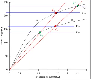
Fig. 2.1 V-I characteristics of an induction machine (shown in black) and excitation capacitor (shown in red) and the steady state
voltage levels built-up shown using blue lines. 18 Fig. 2.2 Equivalent two-axis circuit of an SEIG. 21 Fig. 2.31 Stators of the two 7.5 hp induction machines used in the
investigations. 24
Fig. 2.32 Rotors of the two 7.5 hp induction machines used in the
investigations. 25
Fig. 2.33 Experimental setup of the DC motor coupled ALSEIG
and CRSEIG systems used in the investigations. 25 Fig. 2.34 Experimental setup of the DC motor coupled CRSEIG
system with the load bank, capacitor bank, Tektronix oscilloscope and Fluke power quality analyser used in the
investigations. 25
Fig. 2.41 Calculated and measured results of aluminum-rotor SEIG under RL load of 200 and 0.26 H after the machine reached a rated speed of 1 pu at an excitation capacitance
of 65 µF. 27
Fig. 2.42 Calculated and measured results of copper-rotor SEIG under
RL load of 340 and 0. 44 H after the machine reached a rated speed of 1 pu at an excitation capacitance of
39.6 µF. 28
Fig. 2.51 Effects of varying frequency of current in the conductor. 30 Fig. 2.52 Current distribution 32 Fig. 2.53 Cross-section of the rectangular rotor bar taken into
consideration. 32
Fig. 2.61 Measured saturation characteristics of both aluminum- and
xii Fig. 2.62 Magnetizing inductance of 7.5 hp aluminum rotor SEIG
used in the investigation. 39 Fig. 2.63 Magnetizing inductance of 7.5 hp copper rotor SEIG
used in the investigation. 40 Fig. 2.71 Calculated and measured reactive and real power profiles
under RL load for aluminum-rotor SEIG at a rotor speed
of 1 pu. 42
Fig. 2.72 Calculated and measured reactive and real power profiles under RL load for copper-rotor SEIG at a rotor speed
of 1 pu. 43
Fig. 2.73 Power loss due to proximity effect as a function of
frequency of rotor current. 45
Fig. 3.21 Measured maximum output power at rated stator current,
stator voltage and speed for both CRSEIG and ALSEIG. 52 Fig. 3.22 Measured reactive power (VAR) requirement and
capacitive reactance (Xc) at rated stator voltage and speed for both CRSEIG and ALSEIG during incremental
loading of the machines. 53 Fig. 3.23 Measured saturation characteristics of aluminum- and
copper-rotor machines at their rated frequency. 54 Fig. 3.24 Measured voltage regulation characteristics for CRSEIG
and ALSEIG at rated speed and capacitance of 37µF
and 65 µF. 55
Fig. 3.25 Measured voltage regulation characteristics at rated
speed for both CRSEIG and ALSEIG. 56
xiii the switched capacitor bank system used in this research. 59 Fig. 4.22 Finite impulse response filter for wavelet decomposition. 62 Fig. 4.23 Stator current and load current profiles obtained through
1000:1 turns ratio current sensor without capacitor
compensation. 63
Fig. 4.24 Second-order multiple feedback bandpass filter. 63 Fig. 4.25 Measured high frequency waveforms obtained as output
voltages of the band pass filter stage during load application. 64 Fig. 4.26 Experimental results for voltage regulation. 66 Fig. 4.27 Calculated results for voltage regulation. 67 Fig. 4.28 Flowchart of the step by step process involved in calculating
the capacitance using the SEIG-PSO algorithm. 70 Fig. 4.29 Searching points and terminal phase voltage of particle 1
obtained from numerical investigations under a load of
R=30 Ω and XL=22.5 Ω. 71
Fig. 4.30 PSO performance (estimated error) as a function of iteration
time for varying loading conditions. 71 Fig. 4.31 Measured results for voltage regulation using switched
capacitor scheme. 72
Fig. 4.32 Calculated results for voltage regulation using switched
capacitor scheme. 73
Fig. 4.33 Experimental setup of the wavelet/PSO based module. 74
Fig. 5.1 Short-circuit voltage and current profiles of copper-rotor
xiv
NOMENCLATURE
B : Magnetic flux density
: Skin depth
E : Electric field intensity
: Permittivity
f : Frequency of induced current
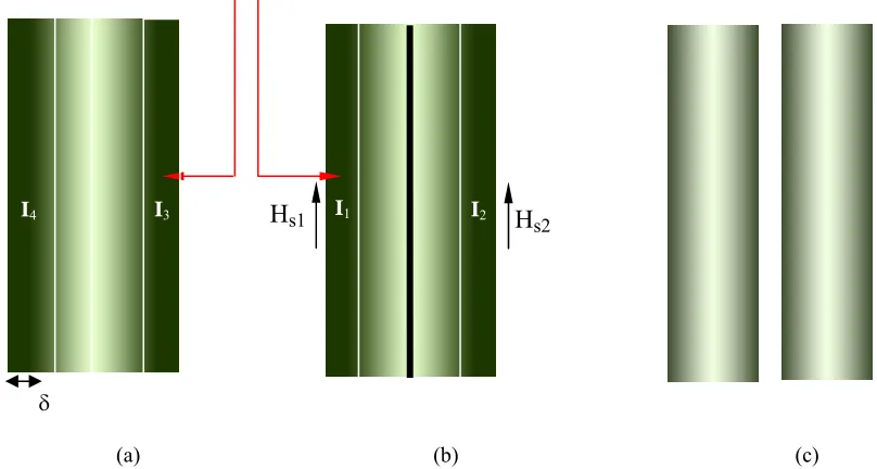
h : Height of the bar Hs1, Hs2 : Magnetic field intensity
I : Current in the rotor bar
J : Current density
: Conductivity of the material µ : Absolute magnetic permeability
w : Width of the bar
: Angular speed
l : Length of the bar
Kr : Resistance coefficient
Kl : Inductance coefficient
Rr_skin : Skin effect coefficient of resistance
Llr_skin : Skin effect coefficient of inductance
Rr0 : Original rotor resistance
Llr0 : Original rotor inductance
Rr_eff : Effective resistance of rotor
Llr_eff : Effective inductance of the rotor
Cr_prox : Multiplication factor of rotor resistance
1
1.0 INTRODUCTION
1.1.
Introduction to Distributed Wind Power Generation and
Induction Generators
Over the years, energy policy in Canada has emphasized large centralized electricity generation and long-distance, high-voltage transmission from centralized sources such as large-scale hydro, coal, natural gas and nuclear power plants. This centralized energy infrastructure is becoming more challenging as demand for clean, reliable and affordable electricity generation grows. North America’s centralized grid system stressed to its limits [1] has become vulnerable and increasingly brittle [2]. Over-reliance on large, polluting and expensive generation and transmission is no longer an option that Canadians would endorse. Hence, renewable energy sources are rapidly becoming a key contributor to Canada’s electricity supply mix. As the nation’s energy infrastructure ages, moving towards clean and inexhaustible sources of electricity is becoming a precondition of Canada’s continued economic success in a competitive global market. Social, health and environmental constraints are fuelling a shift in national and regional energy policy, not only in Canada, but around the world. Distributed generation is the answer for the above issues.
Distributed generation refers to a variety of power-generating modules that can be combined with load management and energy storage systems to improve the quality and/or reliability of the electricity supply. They are "distributed" because they are placed at or near the point of energy consumption, unlike traditional "centralized" systems, where electricity is generated at a remotely located, large-scale power plant and then transmitted down power lines to the consumer.
2 Distributed energy encompasses a wide range of technologies including wind turbines, solar power, fuel cells, micro-turbines, reciprocating engines, load reduction technologies, and battery storage systems. The effective use of grid-connected distributed energy resources can also require power electronic interfaces and communications and control devices for efficient dispatch and operation of generating units.
Diesel- and petrol-fueled reciprocating engines are one of the most common distributed energy technologies in use today, especially for standby power applications. However, they create significant pollution (in terms of both emissions and noise) relative to renewable energy sources, and their use is actively discouraged by many municipal governments. As a result, they are subject to severe operational limitations not faced by other distributed generating technologies.
Furthermore, distributed energy technologies are playing an increasingly important role in the nation's energy portfolio. They can be used to meet peaking power, backup power, remote power, power quality, as well as cooling and heating needs. Distributed energy also has the potential to mitigate congestion in transmission lines, reduce the impact of electricity price fluctuations, strengthen energy security, and provide greater stability to the electricity grid. Distributed power generators are small compared with typical central-station power plants and provide unique benefits that are not available from centralized electricity generation. Many of these benefits stem from the fact that the generating units are inherently modular, which makes distributed power highly flexible. It can provide power where it is needed, when it is needed. And because they typically rely on renewable resources, the generators can be quieter and less polluting than large power plants, which make them suitable for on-site installation in some locations. The use of distributed energy technologies can lead to improved efficiency and lower energy costs, particularly in combined cooling, heating, and power (CHP) applications. CHP systems provide electricity along with hot water, heat for industrial processes, space heating and cooling, refrigeration, and humidity control to improve indoor air quality and comfort [3].
3 on a small number of powerful servers networked with a larger number of desktop personal computers, all of which help to meet the information processing demands of the end users.
Wind power is becoming increasingly popular and is the fastest growing generation form because of its promising potentials for development. Government incentives have been successful, and the efficiency, longevity, and the overall quality of wind turbines have been constantly increasing. Residential wind turbines (producing 100 kW or less) have become a growing market area, as people are trying to reduce their dependency on the conventional power grid.The quality of Canada’s wind resource is as good as or perhaps even better than any of the world’s leading wind energy producing nations such as Germany, Spain and the United States. With abundant land mass and lengthy coastlines, Canada has top quality wind sites. Canada’s total electrical demand could be met by tapping the wind potential of just one quarter of a percent of its land mass. Canadian Wind Energy Association (CanWEA), believes that wind energy can satisfy 20 percent of Canada’s electricity demand by 2025. Achieving this vision will pay huge dividends such as adding 55 GW of clean generating capacity that will strengthen electrical grids and head off potential power shortages, thus stabilizing electricity prices and cutting Canada’s annual greenhouse gas emissions by 17 Megatonnes [4].
The residential or distributed wind generators wind turbines use permanent magnet or self-excited generators to supply small demands effectively. A self-excited induction generator (SEIG) is an ideally suited electricity generating system for island operation of WDG as it becomes tedious and highly expensive to lay transmission lines over or under water, through mountainous areas and across long distances. A stand-alone SEIG driven by wind turbine is capable of supplying power to domestic, industrial and agricultural loads, particularly in the remote and hilly areas where conventional grid supply is not available. Installation of SEIG reduces the high maintenance and installation costs as large amounts of metal and raw material use can be minimized, infrastructure and transmission losses which occur when regular power grids or transmission lines are installed.
4 this topic is primarily due to the application of SEIGs in distributed wind power generation (DWPG). Over the years SEIG has emerged as an alternative to the conventional synchronous generator for such applications [5].
1.2.
Case Studies of Distributed Wind Power Generation in North
America
Selected case studies from [6] and [7] show some examples of isolated wind farms in Canada. Ramea Island, about 10 km off the south coast of Newfoundland, Canada, which is home to approximately 700 inhabitants, used one or more of three installed 925 kW diesel generators, with an average fuel efficiency of around 4 kWh/litre, to meet its electricity requirements. The latest island wind farm installed there produces around 10% to 13% of the 4.3 GWh consumed annually by the community, thus reducing the amount of fuel purchased for diesel generators. The island wind farm at Prince Island, Sault Ste. Marie in Ontario, Canada, produces 534 GWh per year, with 189 MW of installed capacity. In 1992 and 1993, the Yukon Energy Corporation of Canada installed a 150 kW wind energy generation system on Haeckel Hill, a shoulder of Mt. Sumanik, at an altitude of 1,430 m, approximately 750 m above the valley floor where the territory’s capital, Whitehorse, is located. The Whitehorse grid, which is isolated from Canada's national electrical grid, also hosts 0.8 MW wind turbine capacity, provided at Haeckel Hill. A small stand-alone system installed in Southern Alberta allows a farm to operate independently off the grid. The farm had been connected to the grid, but the owner wished to have the farm autonomously powered, to reduce the environmental impact on his farm and home energy use. The farm’s wind energy system supplies power to a residence for a family of four, a machine shop, a water well and yard lights. The rolling prairies of Alberta, between Calgary and Red Deer, are one of the most productive agricultural areas in Western Canada. A wheat farmer, who wanted independence from the electric utility, purchased a 10 kW wind turbine to supply all of his power requirements. The Trochu Wheat Farm was already connected to a power grid, but the farmer’s goal was a stand-alone system that would survive inflation and have less environmental impact in comparison to the coal used to produce electricity for the grid.
5 off-grid since it was built in 1972. When the house was built, the nearest utility was over a mile away, and it would have cost between $60,000 and $70,000 to connect to the utility lines. The owners decided to install a hybrid electric system powered by wind, solar, and a generator for a cost of about $19,700. Electric appliances in the home include television, stereo, two computers, toaster, blender, vacuum cleaner, and hair dryer. The largest electric loads are created by a well pump and washing machine [8].
1.3.
Background Literature on Aluminum- and Copper- Rotor
Induction Machines
As pointed out above, over the last decade, there has been a growing concern over the depletion of fossil fuels and more light has been shed on the usage and development of electric motors in different fields of application like hybrid electric vehicles and wind power generation. People who feel the heat of the future will strive to be in possession of a highly reliable motor. To maximize the reliability without overspending, induction machines need to be properly matched to the specific application. With this consideration, the choice between various rotor constructions needs to be evaluated. Higher efficiency electrical machines can reduce dependence on oil; lower greenhouse gas emissions and help the industry stay economically competitive by reducing energy costs. Millions of induction machines are sold in the world annually [9].
Conventional induction motors use less efficient aluminum rotors because fabrication by pressure die casting is a well established and economical method. Conventional wisdom states that copper conductors are the most reliable and outperform their aluminum counterparts, since the electrical conductivity of copper is 60% more than aluminum. Recent developments in the die casting process that produces copper rotors can easily increase the machine’s efficiency by up to 2.1% [10]. Air pollution would also decrease as a direct result of reduced energy consumption. Use of copper rotors can also reduce motor operating temperatures by 5oC to 32oC [11]. As a general rule, for every 10oC increase in the motor operating temperature, the insulation life of the motor is halved. Therefore, this data indicates that the lifetime of motors using copper rotors may be extended by 50% or more, with proper maintenance.
6 the latest generation of US army severe duty hybrid electric vehicles. These machines were manufactured by Reliance Electric and it is stated that the die cast copper rotor technology was the only way they could meet the rigorous military requirements for weight, size and performance. It is also mentioned that, since copper is a better conductor of electricity and has lower resistance; copper rotors can be smaller, run cooler and have a higher power density. Hence, copper rotors may improve the efficiency of the system and result in a more fault tolerant system [12].
The nameplate efficiency of a practical, in-service, 15 hp, 1,800 rpm aluminum-rotor induction machine today is about 89.5%, which is below the 1997 Energy Policy Act standard of 91%. As demonstrated by many other researchers, the adoption of copper rotors should bring efficiencies to the 94 to 96% range exceeding the requirements of today’s NEMA premium efficiency motor, nominally 93% [13]. In addition, analyses by motor manufacturers have shown that copper rotors can be employed to reduce overall manufacturing costs at a given efficiency or to reduce motor weight, depending on which attribute the designer chooses to emphasize. The potential energy savings achievable through the use of copper rotors is substantial. The U.S. Department of Energy reports that motors above 1/6 hp use about 60% of all electricity generated in the United States and the medium power motors (1 to 25 hp) are the favored candidates for conversion to copper rotors [14]. In Canada alone, 1 percentage increase in the motor electrical energy efficiency would save roughly $200 million and as a result, 0.5 million barrels of oil annually. As Canada and the world move rapidly towards increased dependence on wind power generation, aluminum and copper can play an important role in the rotor construction of SEIG [15].
1.4.
Previous research performed on SEIGs
The phenomenon of self excitation in induction machines has been known for more that 70 years. In this section works carried out previously in the area of self excited induction generators using squirrel cage rotors, especially in the field of wind power application are reviewed. Research is previously performed in the following areas:
o Modelling
7
o Voltage build up
o Steady state analysis of isolated induction generators o Steady state analysis of generators connected to the grid o Parallel operation of induction generators
o Voltage regulation and control o Transient analysis.
Like the induction motors, induction generators are generally classified on the basis of rotor construction. They can be wound rotor or squirrel cage type. Wound rotor induction generators are generally used as Doubly Fed Induction Generators (DFIG) while squirrel cage rotors are used as grid connected or isolated type induction generators. Depending on the type of prime movers and their control mechanism induction generators can be broadly classified as [16].
o Constant Speed Constant Frequency o Variable Speed Constant Frequency o Variable Speed Variable Frequency
For variable speed corresponding to the changing speed of the prime mover, SEIG can be conveniently used for loads which are essentially frequency insensitive. This scheme is gaining importance for stand-alone wind power applications.
8 SEIG, and the analysis of SEIG feeding an induction motor has been done by other authors [16] using d-q frames of reference.
In the steady state analysis, per phase equivalent circuit of the SEIG has been developed from the classical model of an induction machine. The main feature that distinguishes an induction machine from other electrical machines is that, like the transformer, the secondary currents are created totally by magnetic induction. In an isolated power system consisting of the induction generator, the excitation capacitor and load, both the terminal voltage and frequency are unknown and have to be computed for a given speed, capacitance and load impedance. Usually there are four unknowns, reactance of the excitation capacitor Xc, magnetizing reactance Xm, per unit frequency a,
and per unit speed b. Early articles on this subject emphasised on evaluating the value of the minimum capacitance required for self excitation. Two different methods of solution have been used namely, the loop impedance method [26]-[29] and the nodal admittance method. Both these methods used the classical model of the induction machine. In the loop impedance method, for a given load and speed, two non-linear simultaneous equations in per unit frequency, a and magnetizing reactance, Xm are obtained by
equating the real and imaginary terms of the complex loop impedances respectively to zero. The generator performance can then be evaluated by solving these equations. An alternative method of solution using the steady-state equivalent circuit is by considering the nodal admittance method described in [30]-[32].
By means of loop impedance or nodal admittance method technique, equations are obtained and then separated into its real and imaginary parts to solve for the per unit frequency a and then for capacitive reactance Xc or magnetizing reactance, Xm . Chan [30]
9 based on eigenvalues and eigenvalue sensitivity analyses has also been reported in [36] and [37]. Harrington [35] has proposed a method based on the analysis of the complex impedance matrix of the induction generator when loaded with a general inductive load.
1.5.
Research objectives of this thesis
a) Development of Analytical model of SEIG for improved accuracy through incorporation of AC conduction effects in the rotor-bar of SEIG
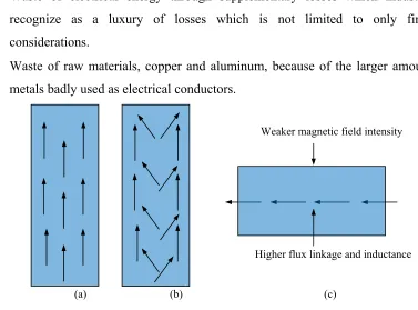
The analysis of the performance of induction machines due of variation of frequency has been reported by several authors [38]–[41]. The frequency of the stator voltage is dependent on rotor speed, magnitude of the excitation capacitance and load [39]. The variation of stator frequency has a profound effect on the rotor parameters. This in turn influences the performance of the machine. Otherwise, in case of a SEIG, the frequency of current in the rotor is affected by the varying load and speed of the wind turbine. The resulting high frequency of current gives rise to a phenomenon called the “Skin Effect”. Skin effect plays an important role in the performance of the SEIG due to higher current density at the surface of the rotor bars [42].
Until now, a conductor subjected to skin effect has been considered to be isolated and outside the influence of any magnetic field, except its own. This assumption is no longer valid when another conductor is in its vicinity; a further distortion in current density occurs due to the interaction of the magnetic field of adjacent rotor conductors. The magnetic flux of one bar induces an e.m.f. in the adjacent conductors, increasing the non uniformity of current density. If two conductors in close proximity carry currents in opposite directions, their electromagnetic fields are opposed to one another and tend to force the conductors apart. There exists a decrease in flux linkages around the adjacent parts of conductors and an increase around the outer parts of the same conductor; which results in a concentration of current in the adjacent parts, where back e.m.f. is at a minimum. If the current flows in the same direction, it tends to be concentrated in the remote parts of the conductors. This is known as the “Proximity Effect” which also increases the resistance of the conductors, hence, the Joule losses [43].
10 copper is a better substitute for aluminum in general, we can increase the efficiency of copper-rotor induction generators if these effects are carefully dealt with. As reported in [44], these effects have been the only concern in further increasing the efficiency of copper-rotor machines and the higher conductivity of copper allows the rotor designer to use these effects to tailor the behavior of the rotor to improve machine performance. Research conducted in [42]-[46] show that the proximity effect is significant in the active length of the conductors and the impact of Joule losses in the design of rotor conductors is large due to the dissipating energy, causing thermal problems.
The research on aluminum- and copper-rotor SEIGs considering skin and saturation effect has been demonstrated in [47]. However, the research performed on SEIGs till date does not show their performance under the influence of proximity effect. Chapter 2.0 of this thesis explains the analytical model of a SEIG developed considering both skin and proximity effects. The influence of proximity effect on the performance of both the machines is analyzed. Exclusive qualitative analysis of real power, reactive power and power loss due to proximity effects at different static loads is accomplished in detail for both the machines. The simulated results are experimentally verified for two industrial 7.5 hp aluminum- and copper-rotor induction machines.
b) Study of commercially available niche CRIM and conventional ARIM to be used as self-excited induction generators in distributed wind power generation
A commercially available induction motor to the general consumer can be used as a SEIG. It is readily available to the consumer for any application (motoring/ generating). Buying a generator directly might be expensive as low rating generators for small wind farms are not mass produced. However, the performance of these motors as SEIGs can be only judged based on their voltage regulation, frequency regulation and VAR requirement characteristics at different operating conditions. Recently, due to the growing cost and complexity of voltage regulating schemes the need has been felt to develop an economical regulating scheme and also minimally modify the induction motor to improve its generating characteristics and reduce its dependency on regulating schemes.
11 exclusively studies the suitability of the relatively newer copper-rotor induction motor (CRIM) and the conventional aluminum-rotor induction motor (ARIM) for use as a SEIG in DWPG. Experimental investigations are performed on two 7.5 hp CRIM and ARIM and the measured results are corroborated by discussions.
c) A novel low-cost embedded system based on Daubechies wavelet transforms and swarm intelligence technique for voltage regulation in SEIGs for distributed wind power generation.
Major challenges in an SEIG are its poor voltage and frequency regulation, since there is no separate DC excitation system. As a load is applied, the VAR supplied by the capacitance of the parallel combination of the excitation capacitance and the connected load must match the VAR demanded by the machine as dictated by the magnetizing curve. In other words, the VAR, required by the machine to maintain self-excitation and the load must be provided solely by the excitation capacitor. Consequently, as the load is increased, there is a decrease in magnitude of the terminal voltage and frequency. Various techniques for improving voltage regulation such as a switched capacitor scheme, electronic load controllers, variable VAR controllers and other solid state controllers are reported in the literature [48]-[55], which improve the performance of a SEIG significantly, but involve complex and expensive control hardware.
Understanding the significance and the need for a low-cost incomplex voltage regulation scheme in a SEIG for distributed wind power generation, chapter 4.0 proposes a part of an exclusive control scheme involving the developed particle swarm optimization (PSO) and the discrete wavelet transforms (DFT) for voltage regulation.
12 integrated with a static synchronous compensator (STATCOM) for better resolution and performance in voltage regulation. Further background study on the developed schemes and mathematical models will be provided in their respective sections.
d) An experimental three phase short-circuit fault analysis in SEIGs for distributed wind power generation
One of the challenges in an SEIG system is fault detection in the system. Faults across the high-voltage terminals of the generator lead to economic losses and power outages. A study performed by the Electric Power Research Institute (EPRI) estimated the cost of power interruptions in the US at $119 billion per year [56]. Forced outages are the primary concern of the remote area consumer for causing economic duress. The SEIG is attractive for DWPG as the terminal voltages of the system collapse during short-circuit faults and hence, the excitation of the machine is cut-off driving the machine to just run freely at the wind turbine rotor speed. However, it is necessary for the fault to be detected and communicated to the operator in order to resume operation after fault inspection and clearance.
Generally, when power line fault occurs, the conventional devices such as auto-reclosing circuit breakers or over-current sensors are used to detect the current amplitudes and break the circuit for power transfer termination and safeguard the generator and load. Also, the detection can be communicated to the operator based on the post-fault information gathered.
13 Hence, chapter 5.0 of this thesis shows this meritorious self protecting mechanism of the SEIG system through fault analysis and thus its usability in distributed generation. Also, the wavelet based transient detection scheme which is developed in this thesis for voltage regulation, explained in later chapters, can be used for fault detection and classification through conditional threshold selection, hence making the wavelet based module a dual purpose module for voltage regulation and fault detection in distributed wind power generation.
1.6.
References
[1] http://www.ornl.gov/info/ornlreview/v38_1_05/article11.shtml,“More power to the grid,” Oak Ridge National Lab. Review, 38,2005.
[2] A. B. Lovins, K. E. Data, T. Feiler, K. R. Rabago, J. N. Swisher, and A. Lehmann, “Small is profitable: The hidden economic benefits of making electric resources the right size,” 2002.
[3] http://www.nrel.gov/learning/eds_distributed_energy.html,“Distributed Energy. [4] http://www.canwea.ca, “Wind vision 2025: Powering Canada's Future,”
November 2010.
[5] B. Singh, M. Singh, and A. K. Tandon, “Transient performance of series-compensated three phase self excited induction generator feeding dynamic loads,”
IEEE Trans. on Industry Applications, vol. 46, no. 4, July/ August 2010.
[6] www.nrcan-rncan.gc.ca, Natural Resources of Canada, Case Studies, “390 kW - Isolated-grid/Canada,” February 2009.
[7] http://www.smallwindenergy.ca, “Small wind case studies and success stories,” Canadian wind energy association.
[8] www.energy.gov, Small Wind Electric Systems, A US consumer Guide.
[9] W. R. Finely and M. M. Hodowanec, “Selection of copper vs. aluminum rotors for induction motors,” in Proc. IEEE Petroleum and Chemical Industry Conference, 2000.
[10] Copper.org, CDA Press Releases, “Building a better electrical motor,” January 2005.
[11] Copper.org, CDA Press Releases, “Die-cast copper rotor improves motor efficiency motor,” January 2005.
[12] Copper.org, CDA Press Releases, “Copper Motor rotors boost performance of Army trucks,” January 2007.
[13] J. G. Cowie, D. T. Peters, and D. T. Brender, “Die-cast copper rotors for improved motor performance,” in Proc. IEEE Pulp and Paper Industry Technical Conference, 2003.
[14] Canadian Copper and Brass Development Association, “Wind power and copper in Canada,” No. 154, 2006.
14 [16] R.C. Bansal, “Three Phase Self Excited Induction Generator: An overview,” IEEE
Transaction on Energy Conversion, Vol.20, No. 2, pp. 292-299, Jun. 2005.
[17] P.C. Krause and C.H. Thomas, “Simulation of Symmetrical Induction Machinery,” IEEE Transaction on Power Apparatus and Systems, Vol. PAS-84, No. 11, pp. 1038-1053, Nov. 1965.
[18] L. Wang and C.H. Lee, “Dynamic Analysis of Parallel Operated Self-Excited Induction Generators feeding an Induction Motor Load,” IEEE Transaction on Energy Conversion, Vol. 14, No. 3, pp. 479-486, Sep. 1999.
[19] R.H. Nelson, T.A. Lipo and P.C. Krause, “Stability Analysis of a Symmetrical Induction Machine,” IEEE Transaction on Power Apparatus and Systems, Vol. 88, pp. 1710-1717, Nov 1969.
[20] E. Levi, “Application of the Current State Space Model in Analyses of Saturated Induction Machines,” Electric Power Research, pp. 203-216. 1994.
[21] R. Djamila R and R. Toufik, “An approach for the Modeling of an Autonomous Induction Generator Taking into account the Saturation Effect,” International Journal of Emerging Electric Power Systems, Vol. 4 No. 1, pp. 391- 2005.
[22] P.C. Krause, Analysis of Electric Machinery and Drive Systems, 2nd Edition, IEEE Press, 2002.
[23] O.I. Okoro, “Matlab Simulation of Induction Machine with Saturable Leakage and Magnetizing Inductances”, The Pacific Journal of Science and Technology, Vol. 5, No. 1, pp. 5-15, Apr. 2003.
[24] D. Seyoum, “The Dynamic Analysis and Control of a Self-Excited Induction Generator driven by a Wind Turbine,” Ph. D. Dissertation, The University of New South Wales, Australia, 1999.
[25] S. S. Murthy and S. Acharya, “Matlab Based Steady State Analysis of Self Excited Induction Generator,” The Fifth International Conference on Power Electronics and Drive Systems, Vol. 1, pp. 749-753 Nov. 2003.
[26] S.S. Murthy, O.P. Malik and A.K. Tandon, “Analysis of Self-Excited Induction Generators,” Proceedings of IEE, Vol. 129, Part C, No. 6, pp. 260-265, Nov. 1982.
[27] N.H. Malik and S.E. Haque, “Steady State Analysis and Performance of an Isolated Self-Excited Induction Generator,” IEEE Transaction on Energy Conversion, Vol. EC-1, No. 3, pp.134-139, Sept. 1986.
[28] T.F. Chan, “Steady State Analysis of Self Excited Induction Generators,” IEEE Transactions on Energy Conversion, Vol.9, No. 2, pp. 288-296, Jun. 1994.
[29] N.H. Malik and A.A. Mazi, “Capacitance Requirements for Isolated Self Excited Induction Generators,” IEEE Transaction on Energy Conversion, Vol. EC-2, No. 1, pp. 62-68, Mar. 1987.
[30] T.F. Chan, “Analysis of Self-Excited Induction Generators Using an Iterative Method,” IEEE Transactions on Energy Conversion, Vol. 10, No. 3, pp. 502-507 Sept. 1995.
15 [32] S. U Alghuwainem, “Steady-State Analysis of an Isolated Self-Excited Induction Generator supplying an Induction Motor Load,” IEEE Transaction on Energy Conversion, Vol. 14, Issue 3, pp. 718-723, Sept. 1999.
[33] T.F. Chan, “Capacitance Requirements of Self-Excited Induction Generators,”
IEEE Transactions on Energy Conversion, Vol. 8, No. 2, pp. 304-311, Jun. 1993. [34] S.S. Murthy and A.J.P. Pinto, “A Generalized Dynamic and Steady State Analysis
of Self Excited Induction Generator (SEIG) Based on Matlab,” Proceedings of the Eighth International Conference on Electrical Machines and Systems, Vol. 3, Issue , pp. 1933-1938, Sep. 2005.
[35] R.J. Harrington and F.M.M. Bassiouny, “New Approach to Determine the Critical Capacitance for Self-Excited Induction Generators,” IEEE Transactions on Energy Conversion, Vol. 13, No. 3, pp. 244-249, Sep. 1998.
[36] L. Wang and C.H. Lee, “A Novel Analysis on the Performance of an Isolated Self-Excited Induction Generator,” IEEE Transactions on Energy Conversion, Vol. 12, No. 2, pp. 109-117, Jun. 1997.
[37] L. Wang and J.Y. Su, “Determination of Minimum and Maximum Capacitance of an Isolated SEIG using Eigenvalue Sensitivity Approach,” Proceedings of International Conference on Power System Technology, Vol.1, pp. 610-614, Aug. 1998.
[38] J. Langheim, “Modeling of Rotor Bars with Skin Effect for Dynamic Simulation of Induction Machines,” Conference Record of the 1989 IEEE Industry Application Society Annual Meeting, Vol. 1, pp. 38-44, 1989.
[39] H. Kabbaj, X Roboam, Y. Lefevre and J. Faucher, “Skin Effect Characterization in a Squirrel Cage Induction Machine,” Proceedings of the IEEE International Symposium on Industrial Electronics, Vol. 2, pp. 532-536, 1997.
[40] N. Erdogan, T. Assaf, R. Grisel and M. Aubourg, “An Accurate 3-phase Induction Machine Model Including Skin Effect and Saturations for Transient Studies,” Sixth International Conference on Electrical Machines and Systems, pp. 646-649, 2003.
[41] O.I. Okoro, “Transient State Modeling of Asynchronous Generator with Skin Effect,” The Pacific Journal of Science and Technology, Vol. 5, No. 2, pp. 63-71, 2004.
[42] K. Hafiz, G. Nanda, and N. C. Kar, “Performance analysis of aluminum and copper rotor induction generators considering skin and thermal effects,” IEEE Trans. on Industrial Electronics, vol. 57, January 2010.
[43] J. D. Milburn, “Skin and proximity effects in heavy-current conductors,” Student’s Quarterly Journal, March 1969, pp. 172-180.
[44] Canadian Copper and Brass Development Association, “Technology transfer report - The die cast copper rotor motor,” April 4, 2004.
[45] R. Wrobel, A. Mlot, and P. H. Mellor, “Investigation of end-winding proximity losses in electromagnetic devices,” in Proc. XIX IEEE Inter-national Conference on Electric Machines, 2010.
16 [47] K. Hafiz, G. Nanda, and N. C. Kar, “Skin effect modeling of self excited
induction generator in wind power application,” in Proc. of IEEE Canadian Conference on Electrical and Computer Engg., May 2008.
[48] L. Wang and C. M. Cheng, “Selection of magnetizing curves for accurately simulating a three-phase self-excited induction generator feeding a single-phase load,” IEEE Power Engineering Society Winter Meeting, vol. 1, no. 1, pp. 286-290, 2000.
[49] N. H. Malik and A. A. Mazi, “Capacitance requirements for self excited induction generators,” IEEE Trans. on Energy Conversion, vol. 2, 1987.
[50] S. N. Mahato, S. P. Singh, and M. P. Sharma, “Capacitors required for maximum power of a self-excited single-phase induction generator using a three-phase machine,” IEEE Trans. on Energy Conv., vol. 23, 2008.
[51] B. Singh, S. S. Murthy, and S. Gupta, “STATCOM based voltage regulator for self excited induction generator,” IEEE Trans. Ind. Electronics, vol. 53, no.5, pp. 1437-1452, Oct. 2006.
[52] K. H. Youssef, M. A. Wahba, H. A. Yousef, and O. A. Sebakhy, “A new method for voltage and frequency control of stand-alone self excited induction generator using PWM converter with variable DC link voltage,” in Proc. of American Control Conference, pp. 2486-2491, 2008.
[53] R. Bonert and S. Rajakaruna, “Self excited induction generator with excellent voltage and frequency control,” Proc. Inst. Elect. Eng. Gen., Tran. and Dist., vol. 145, pp. 33-39, Jan. 1998.
[54] S. C. Kou and L. Wang, “Dynamic eigen-value analysis of a self-excited induction generator feeding an induction motor,” in Proc. IEEE Power Engg. Society Winter Meeting, vol. 3, no. 1, pp. 1393-1397, 2001.
[55] S. C. Kou and L. Wang, “Steady-state performance of a self-excited induction generator feeding an induction motor,” Journal of Electric Power Components and Systems, pp. 581-593, 2002.
17
2.0 MODELING OF ALUMINUM- AND COPPER-ROTOR
SEIGs INCORPORATING PROXIMITY EFFECT IN THE
ROTOR BARS
2.1 Process of self-excitation and voltage build up in SEIGs
The phenomenon of self-excitation in induction machines has been known and studied for over several decades [1]. When an induction machine is connected to an AC source, a component of its stator current is used to build-up the air gap magnetic flux whether the machine works as a motor, brake or a generator [2]. If the machine operates as a generator, reactive power is required to build up the magnetic flux. This reactive power can be provided from the grid. In an isolated mode, this excitation can be provided by an external capacitor of appropriate value. In other words, to build up the voltage across the generator terminals, some means of excitation is required [3]. To achieve a given voltage level, the external capacitors must supply the required magnetizing current and hence the reactive power.
An induction generator without any external source, using capacitors can self-excite if there is a remnant magnetic flux in the machine core [4]–[5] or residual charge across the capacitor terminals. The residual magnetism in the field circuit produces a small voltage. That voltage produces a small capacitive current flow. This boosts up the voltage which further increases the capacitive current until the voltage is built up. Thus a three phase induction machine can be made to work as a self-excited induction generator provided capacitance connected across the stator terminals have sufficient charge to provide necessary initial magnetizing current [6]–[9]. In such a case, this phenomena is known as capacitor self excitation, and the induction machine is called Self Excited Induction Generator (SEIG).
In an induction machine with a capacitor connected across its terminals, if the effect of the small stator resistance Rs and stator leakage inductance Lls are neglected, the
equivalent circuit for no load excitation takes the form of a parallel LC circuit, where L
18 mover, and if the capacitor is charged it provides the exciting current required by the induction generator to produce a magnetic flux. The magnetic flux in the induction generator charges the capacitor to increase the terminal voltage. An increase in the capacitor voltage boosts up the excitation current to the generator to increase the flux which in turn increases the terminal voltage. In this way the voltage and current build up continues until the magnetizing inductance decreases to its saturated value and equilibrium point is attained. The process will continue until steady state is reached.
In order to estimate the level of saturation and the mutual inductance term at a particular operating condition require the representation of the magnetization curve of the induction generator under consideration. The magnetizing characteristic of an induction machine is a curved line. In the absence of saturation of the iron this line should ideally be straight. But due to saturation the line becomes curved beyond a certain excitation current. This curve represents characteristic at a particular rotor speed. If the magnetizing characteristic is obtained at a higher rotor speed, a steeper curve will be obtained as shown in Fig. 2.1. This figure shows the relationship between the size of the excitation capacitance, the rotor speed and generated voltage.
Fig. 2.1. V-I characteristics of an induction machine (shown in black) and excitation capacitor (shown in red) and the steady state voltage levels built-up shown using blue lines. ω2 > ω1 , C1 < C2.
0 50 100 150 200 250
0 0.5 1 1.5 2 2.5 3 3.5 4
Magnetizing current (A)
P
has
e v
olt
ag
e
(V
)
ω1 ω2
C1
C2
V12 V11
V22
V21 C2
19 As the magnetising current produced by a capacitor is directly proportional to the voltage applied to it, the locus of the voltage and current relationship is a straight line. It can be seen from Fig. 2.1 that for each amount of capacitance there is a single point where the inductor and capacitor currents are equal. This is the intersection point of the magnetizing curve and the linear capacitor volt-ampere characteristic at the particular rotor speed at no load. At this point the voltage and current will oscillate at a certain peak value and frequency. Once self-excitation has been initiated, the open circuit voltage to which the machine will self-excite can be calculated i.e.V21 at a capacitance C1 and rotor
speed ω1. If the capacitance is increased (from C1 to C2) a higher voltage, V22 will be
generated at the same speed as the slope of the VI characteristics of the capacitor will be tilt towards the right with increasing value of C. Similarly, at a higher rotor speed, ω2,
higher voltages will be generated depending on the capacitance values.
At low magnetizing current where the magnetizing curve is practically linear, the intersection with the capacitor line is not well defined. This will result in poor flux stability and voltage regulation in this region. This is the minimum value of capacitance beyond which the machine will not maintain or build up excitation at all. Any value of capacitor lower than the minimum will result in loss of excitation if the machine is already generating or will not be able to initiate self excitation if the machine is starting.
20 saturation curve at a point. This point of intersection will be the steady state terminal voltage (V11, V12, V21and V22) and excitation current. If saturation is absent, the curve will
essentially be a straight line and the two lines will not intersect. Consequently there will be no excitation.
The steady state performance characteristics of an isolated self-excited induction generator are influenced by the magnitude of the excitation capacitor and rotor speed. The terminal capacitor must have its value within a certain range to sustain self-excitation. If the value of the excitation capacitor is outside this range, self-excitation will not be possible [12]-[14]. As explained above, the capacitor in such a machine must have a minimum value, Cmin for self excitation to take place. On the other hand in order to
sustain operation, the terminal capacitor must also be below a certain maximum value
Cmax [13]. Both the minimum and maximum values are affected by the machine
parameters, speed and load conditions.
2.2 Analytical Modeling of the SEIG using conventional two-axis
model
Previous research performed on SEIG is mainly concerned with representing the machine by steady state models and the dynamic models. The steady state SEIG is modeled as per phase equivalent circuit. In this circuit the slip and angular frequency are expressed in per unit quantities. Previous authors have used either the loop impedance method [1]-[3] or the nodal admittance method [4]-[6] to analyze the machine performance. In the loop analysis technique the total loop impedance which includes the excitation capacitance is equated to zero. In the nodal admittance method the overall admittance of the SEIG at a certain node is set to zero. These methods give an algebraic expression for magnetizing reactance in terms of generator frequency and other machine parameters and speed. For the determination of the operating frequency a and magnetizing reactance Xm the real and imaginary parts of the sum of admittances of the
rotor, magnetizing and stator branches are separately equated to zero. In these approaches there are usually four unknowns, the magnetizing reactance Xm, the excitation capacitance
Xc, per unit frequency a and per unit speed b. Assuming values of any two, the other two
21 analysis a high order polynomial or a non-linear simultaneous equation is used where the general focus is to find the value of the capacitance required for self-excitation. Several researchers indicated that there is a minimum value of excitation capacitance to initiate self-excitation for a given speed and load condition [7] while some also exploited the maximum value of this capacitance [2], [5] beyond which excitation will not be maintained.
The d-q reference model using Park’s transformation was proposed by Krause and Thomas [8]. This method was further extended by other authors [9]-[11] for dynamic analysis of induction machines. The non-linear differential equations that describe the dynamic performance of an induction machine in an arbitrary reference frame can be derived from the d-q equivalent circuits. To analyse the performance of an induction generator, differential equations describing the excitation capacitance and load are also taken into account. This method has been employed in this thesis to model the SEIG.
(a)
(b)
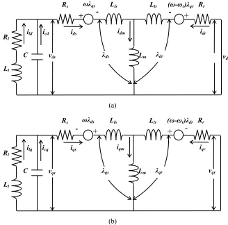
Fig. 2.2 Equivalent two-axis circuit of an SEIG. (a) d-axis. (b) q-axis.
iqr
iqs
(ω-ωr)λdr
icq
ilq
Rl
Ll
C Lm
Lls
Rs Llr Rr
vqs
iqm
ωλds
λqr
λqs
+
vqr
- + -
+ -
idr
ids
(ω-ωr)λqr
icd
ild
Rl
Ll
C Lm
Lls
Rs Llr Rr
vds
idm
ωλqs
λdr
λds
- +
22 The induction machine circuit diagram as presented in Figs. 2.2 (a) and (b), can be modeled using d-q axis reference frame. These figure show the direct and quadrature representation of a squirrel cage induction machine. It is the most commonly used transient state model in the d-q axis frames of reference [10]. The advantage of the d-q axis model is that it is a powerful tool for analyzing the dynamic and steady state conditions, thus providing a complete solution for any dynamics. For steady state analysis, the conventional model and the d-q reference are the same.
From the above figures the d-q axis stator and rotor voltages of an induction machine can be expressed in matrix notation as:
dr i qr i ds i qs i r pL r R r L r m pL m L r r L r r pL r R m L r m pL m pL m L s pL s R s L m L m pL s L s pL s R dr v qr v ds v qs v ) ( ) ( ) ( ) ( (2.1) where dt d p and
m L lr L r L m L ls L s L (2.2) ds i m L dr i r L dr qs i m L qr i r L qr dr i m L ds i s L ds qr i m L qs i s L qs (2.3)
Equation (2.1) may be written as
dq i p dq L dq i dq RL dq
23 where ' dr v qr v ds v qs v dq
v (2.5)
' dr i qr i ds i qs i dq
i (2.6)
r R lr L m L r m L r lr L m L r r R m L r m L s R ls L m L m L ls L m L s R dq RL 0 0 0 0 (2.7) lr L m L m L lr L m L m L m L ls L m L m L ls L m L dq L 0 0 0 0 0 0 0 0 (2.8)Rearranging Equation (2.4)
dq i dq RL dq L dq v dq L dq i
p 1 1 (2.9)
Since the rotor is squirrel cage, vqr and vdr are both equal to zero. The differential
equations representing the capacitor circuit is given by:
ds v qs v p p C cd i cq i (2.10)
where the voltage across the capacitor is vqs and vds and the currents are icq and
icd .respectively. Equation (2.10) can be re-arranged to give:
24 For open circuit conditions, (2.4) through (2.11) form the set of differential equations to represent the system. For a resistive load connected across the terminals of the SEIG and noting that :
lq i cq i qs
i (2.12) and ld i cd i ds
i , (2.13)
Load currents may be expressed as :
ds v qs v ld i lq i l
R (2.14)
In order to take the RL load impedance into account
ld i lq i l pL l R ds v qs v (2.15) or ld i lq i R l L ds v qs v l L ld i lq ip 1 1 (2.16)
2.3 Experimental setup of two industrial 7.5 hp Aluminum- and
Copper-rotor SEIGs
(a) (b)
25
(a) (b)
Fig. 2.32. Rotors of the two 7.5 hp induction machines used in the investigations. (a) Aluminum-rotor. (b) Copper-rotor.
Fig. 2.33. Experimental setup of the DC motor coupled ALSEIG and CRSEIG systems used in the investigations.
Fig. 2.34. Experimental setup of the DC motor coupled CRSEIG system with the load bank, capacitor bank, Tektronix oscilloscope and Fluke power quality analyser used in the investigations.
26 TABLE 1
INDUCTION GENERATOR DATA
Aluminum-rotor SEIG Copper-rotor SEIG
Output power 7.5 hp 7.5 hp
Rated voltage 346 V 460 V
Rated current 12 A 9.5 A
Connections Wye Wye
Number of poles 4 4
Rated speed 1755 rpm 1775 rpm
Rated frequency 60 Hz 60 Hz
Weight 75.9 kg 90 kg
Diameter of rotor 134.9 mm 129.9 mm
Height of rotor bar 25.79 mm 26.6 mm
Width of rotor bar 5.62 mm 5.6 mm
Length of rotor bar 136.8 mm 167.8 mm
Number of conductors 40 40
Conductivity of rotor bar 37.71 μS/mm 59.61 μS/mm
Rs [] 0.38621 0.65417
Rr [] 0.81736 1.48166
Xls [] 0.92557 2.08272
Xlr [] 1.38835 3.12267
Xm[] 40.6851 68.9616
Rc [] 564.580 1031.24
2.4 Validating the developed conventional two-axis model of SEIG
for both copper- and aluminum-rotor SEIGs
and 2 appli and c these calcu in re devel incor done
2.42. The re ed across th copper-rotor e figures, it ulated results esults can b
loped two-a rporating var in the follow
sults shown he stator term
SEIGs resp can be obse s obtained us be explained axis model rious AC co wing section
n in Figs. 2.4 minals at aro pectively, aft erved that th sing the conv
d as elucid can be im onduction eff n.
41 and 2.42 ound 62 sec ter their volt here is a min
ventional tw dated in [25 mproved to
fects in the r
(a)
(b)
(c)
were elicite conds and 82
tages had re nimal variat wo-axis mode 5]-[27]. Res match the rotors of bot
ed under a s 2 seconds fo eached stead
tion in the m el of SEIG. T sults obtaine experimenta th the mach
Cu rr en t [ A ] 2 static RL loa or aluminum
y state. From measured an This variatio ed using th al results b hines which i
Fig. 2 200 Calcul stator
.41. Calculated and 0.26 H af
lated phase vo current profile
d and measure fter the machin oltage profile. es. (d) Calculat
ed positive hal ne reached a ra (b) Calculated ed and measur
(d) lf cycle results ated speed of 1 d stator curren red reactive pow
(a)
(b)
(c)
s of aluminum-pu at an excita nt profile. (c) wer profiles.
-rotor SEIG un ation capacitan
Measured pha
2
nder RL load o nce of 65 µF. (a ase voltage an
Cu
rr
en
t [
A
]
28