University of Windsor University of Windsor
Scholarship at UWindsor
Scholarship at UWindsor
Electronic Theses and Dissertations Theses, Dissertations, and Major Papers
2014
Thermal and Microstructural Analysis of the A356 Alloy Subjected
Thermal and Microstructural Analysis of the A356 Alloy Subjected
to High Pressure in the Squeeze Casting (SC) UMSA Technology
to High Pressure in the Squeeze Casting (SC) UMSA Technology
Platform
Platform
Mohammad Khurshed-Ul Alam University of Windsor
Follow this and additional works at: https://scholar.uwindsor.ca/etd
Recommended Citation Recommended Citation
Alam, Mohammad Khurshed-Ul, "Thermal and Microstructural Analysis of the A356 Alloy Subjected to High Pressure in the Squeeze Casting (SC) UMSA Technology Platform" (2014). Electronic Theses and Dissertations. 5116.
https://scholar.uwindsor.ca/etd/5116
This online database contains the full-text of PhD dissertations and Masters’ theses of University of Windsor students from 1954 forward. These documents are made available for personal study and research purposes only, in accordance with the Canadian Copyright Act and the Creative Commons license—CC BY-NC-ND (Attribution, Non-Commercial, No Derivative Works). Under this license, works must always be attributed to the copyright holder (original author), cannot be used for any commercial purposes, and may not be altered. Any other use would require the permission of the copyright holder. Students may inquire about withdrawing their dissertation and/or thesis from this database. For additional inquiries, please contact the repository administrator via email
Thermal and Microstructural Analysis of the A356 Alloy Subjected to High Pressure in the Squeeze Casting (SC) UMSA Technology Platform
By
Mohammad Khurshed-Ul Alam
A Thesis
Submitted to the Faculty of Graduate Studies through the Department of
Mechanical, Automotive & Materials Engineering in Partial Fulfillment of the Requirements for the Degree of
Master of Applied Science in Engineering Materials at the
University of Windsor
Windsor, Ontario, Canada
2014
Thermal and Microstructural Analysis of the A356 Alloy Subjected to High Pressure in the Squeeze Casting (SC) UMSA Technology Platform
By
Mohammad Khurshed-Ul Alam
APPROVED BY:
______________________________________________ S. Das
Department of Civil and Environmental Engineering
______________________________________________ D. O. Northwood
Department of Mechanical, Automotive and Materials Engineering
______________________________________________ A. Conle
Department of Mechanical, Automotive and Materials Engineering
______________________________________________ F. Ghrib
Department of Civil and Environmental Engineering
______________________________________________ J. H. Sokolowski, Advisor
Department of Mechanical, Automotive and Materials Engineering
iii
DECLARATION OF CO-AUTHORSHIP
Co-Authorship Declaration
I hereby declare that this thesis incorporates material that is a result of joint research, as follows:
This thesis incorporates the outcome of research performed in the field of SEM/EDS Elemental Analysis in collaboration with Dr. Adam Gesing under the supervision of Dr. Jerry H. Sokolowski and Dr. Al Conle. The collaboration is covered in some portions of Sections 4.7-4.8 of Chapter 4 of the thesis. Contributions by the collaborators were primarily through the provision of calculations of micro chemical compositions in SEM/EDS Analysis.
I am aware of the University of Windsor Senate Policy on Authorship and I certify that I have properly acknowledged the contribution of other researcher to my thesis, and have obtained written permission from the co-author to include the above material(s) in my thesis.
I certify that, with the above qualification, this thesis, and the research to which it refers, is the product of my own work. I also certify that the above material describes work completed during my registration as a graduate student at the University of Windsor.
I declare that, to the best of my knowledge, my thesis does not infringe upon anyone’s copyright nor violate any proprietary rights and that any ideas, techniques, quotations, or any other material from the work of other people included in my thesis, published or otherwise, are fully acknowledged in accordance with the standard referencing practices.
iv
ABSTRACT
The effect of cyclic pressure on the thermal and microstructural behaviour of the
A356 alloy and the addition of commercial Al-Sr Master Alloy, Nano Alumina
Master Alloy and a combination of both Master Alloys during the squeeze casting
was investigated in this study. The results show that the α-dendrite growth
temperature was increased and the Al-Si eutectic growth temperature was
decreased substantially, resulting in a super refined, as-cast, equiaxed α-Al cells
and ultra fine dendritic eutectic Si in the modified and unmodified A356 aluminum
alloy. Moreover, very rapid spheroidization of the Si particles was observed within
a very short Solution Treatment time (15min) of the squeeze cast unmodified and
Sr modified A356 alloy. It is expected that the results of this study will lead to a
number of further fundamental and applied research rendering new alloys and
v
DEDICATION
I dedicate this thesis to my beloved parents whom I lost long ago and who were
vi
ACKNOWLEDGEMENTS
I would like to express my heartfelt gratitude to the Almighty Allah who has
created me and who has given me the ability and strength to carry out my research
and the writing of this thesis.
I would like to acknowledge my supervisor Dr. Jerry H. Sokolowski and thank him
for giving me the opportunity to conduct my MASc research project under his
supervision and for providing me with his scientific and technical support. I am
also thankful to the AUTO21 Network of Centres of Excellence for the financial
support provided during my MASc project.
I would like to thank Drs. F. Ghrib, D. Northwood and S. Das for consenting to be
a part of my Advisory Committee as well as for their continued guidance. Their
help and feedback is highly appreciated.
My sincere thanks go to Dr. Al Conle, a Special Member of my Committee, who
has been instrumental in the success of my experiments. His continuous assistance
and support in carrying out my experiments, and in writing my thesis, is very much
appreciated. I would also like to thank to Dr. Adam Gesing and Dr. Marcin
Kasprzak for their scientific and technical support on my project. Dr. Gesing’s
vii
Thanks to Dr. T. Troczynski (University of British Columbia) for providing the
nano Al2O3 Master Alloy and thanks to Professor L. Dobrzanski and Professor Z.
Rdzawski, from the Silesian University of Technology, Poland, for the further
processing of this Master Alloy, for access to their analytical facilities and for
providing the author with comprehensive characterization of the experimental test
samples.
I wish to express my thanks to Ms. Ellen Moosberger for her invaluable assistance
with the editing of this thesis. Special thanks go to my colleagues, Israel Aguilera,
Brandon Hooper, Peter Guba, Paul Marchwica, Bruce Durfy, Andrew Jenner,
Sharon Lackie and Steve Budinsky for their valuable help in my daily activities.
Most of all, I would like to express my deepest gratitude to my wife Kashfia
Nehrin and to my son Ahmad Tashfeen for their absolute love and understanding.
It would have been impossible to complete this master’s thesis without their
viii
TABLE OF CONTENTS
DECLARATION OF CO-AUTHORSHIP ... iii
ABSTRACT ... iv
DEDICATION...v
ACKNOWLEDGEMENTS ... vi
LIST OF TABLES ... xii
LIST OF FIGURES ... xiii
LIST OF APPENDICES ...xxv
LIST OF ABBREVIATIONS/SYMBOLS ... xxvi
CHAPTER ONE - INTRODUCTION ...1
1.0. Background ...1
1.2. Scope of Research ...5
1.3. Objectives ...6
CHAPTER TWO - LITERATURE REVIEW ...8
2.1. Aluminum and Aluminum Alloys ...8
2.1.1. Aluminum ... 8
2.1.2. Aluminum Alloys ... 8
2.1.3. Alloy Designation of Cast Aluminum Alloys ... 9
2.1.4. Importance of Al-Si Alloys ... 10
2.1.5. Al-Si Alloy System ... 11
2.1.6. Mechanical Properties of Al-Si Alloys ... 14
2.1.7. Effect of Minor Common Elements Present in Al-Si Alloys ... 15
2.1.8. The A356 Alloy and Silicon Modification... 16
2.1.9. Chemical Modification and Mechanical Characteristics ... 19
2.1.10. Levels of Si Morphology Modification ... 22
2.1.11. The Nano Alumina Master Alloy (NAMA) ... 23
ix
2.1.13. Heat Treatment ... 28
2.2. Squeeze Casting ...30
2.2.1. History of Squeeze Casting ... 31
2.2.2. Squeeze Casting Processes... 33
2.2.3. Mechanics of Squeeze Casting ... 33
2.2.4. Application of Pressure and its Effect on Solidification ... 35
2.3. Thermal Analysis (TA) ...40
2.4. Silicon Equivalency and Liquidus Temperature ...46
CHAPTER THREE - EXPERIMENTAL METHODOLOGIES ...49
3.1. Material Chemistry of A356 Alloy for Squeeze Casting ...49
3.1.1 Calculations for Sr and Nano Alumina Master Alloy Additives ... 50
3.1.2. A356 Ingot Segregation ... 51
3.1.3. SEM/EDS Analysis of SC UMSA Test Sample Phases and Bulk Chemical Analysis 51 3.2. Squeeze Casting (SC) – UMSA Technology Platform ...52
3.2.1. Background ... 52
3.2.2. SC UMSA Technology Platform's Functional Design ... 53
3.2.3. SC Die ... 53
3.2.4. Test Sample ... 56
3.2.5. Processing Parameters for Programmable Squeeze Casting Experiments ... 57
3.2.6. Test Control Software and Data Collection Procedure for Squeeze Casting Experiments ... 60
3.2.7. Calibration of Thermocouple and Data Acquisition System ... 62
3.2.8. Experimental Procedure for the Squeeze Casting ... 71
3.3. High Temperature Universal Metallurgical Simulator and Analyzer (HT UMSA) ...77
3.3.1. Hardware Platform ... 77
3.3.2. Software Platform ... 79
3.3.3. Solution Treatment Procedure ... 80
3.4. Metallographic Sample Preparation ...80
x
3.6. Measurement of Dendrite Refinements - Secondary Dendrite Arm
Spacing (SDAS) and Dendrite Cell Size ...82
3.7. Experimental Design ...84
CHAPTER FOUR - RESULTS AND DISCUSSION ...87
4.1. Determination of Thermal Characteristics of A356 Alloy ...87
4.2. Determination of Solidification Rate (SR) ...92
4.3. Effect of Cyclic Pressure on the Unmodified A356 Alloy in the SC UMSA Platform ...93
4.3.1. Changes in the Thermal Characteristics of Unmodified A356 Alloy ... 94
4.3.2. Changes in the Internal Energy of the 356 Alloy System ... 98
4.3.3. Changes in the Solidification Rate of Unmodified A356 Alloy ... 99
4.4. Effect of Cyclic Pressure on the Sr Modified A356 Alloy in SC UMSA Platform ...101
4.4.1. Changes in the Thermal Characteristics of Sr Modified Alloy ... 101
4.4.2. Changes in the Solidification Rate of Sr Modified Alloy ... 104
4.5. Effect of Cyclic Pressure on the Nano Alumina Modified A356 Alloys in the SC UMSA Platform...105
4.5.1 Changes in the Thermal Characteristics of Nano Alumina Modified A356 Alloy ... 105
4.6. Effect of Cyclic Pressure on the Sr and Nano Alumina Combined Modified A356 Alloy in the SC UMSA Platform...107
4.6.1. Changes in the Thermal Characteristics of Strontium & Nano Alumina Combined Modified A356 Alloy ... 107
4.7. Microstructural Analysis ...109
4.7.1. Microstructural Analysis of the Unmodified A356 Alloy ... 110
4.7.2. Microstructural Analysis of the Sr Modified A356 Alloy ... 118
4.7.3. Microstructural Analysis of the Nano Alumina Modified A356 Alloy ... 125
4.7.4. Microstructural Analysis of the Sr and Nano Alumina Combined Modified A356 Alloy... 131
4.8. Solution Treatment ...134
4.8.1. SEM/EDS Analysis for Solution Treated UM A356 Alloy ... 140
xi
4.9. Comparison and Correlation between Thermal and Microstructural
Analysis of Unmodified and Modified Alloys ...143
4.10. Comparison with the Alcoa A356 Alloy Wheel ...148
CHAPTER FIVE – SUMMARY AND CONCLUSIONS ...150
5.1. Summary ...150
5.2. Conclusions ...154
CHAPTER SIX - RECOMMENDATIONS FOR FUTURE WORK ...156
REFERENCES/BIBLIOGRAPHY ...157
APPENDICES ...167
xii
LIST OF TABLES
Table 1 - Cast Aluminum Alloy Families . ... 9
Table 2 - Comparison of Two Alloy Designations and Their Chemistries . ... 11
Table 3 - Some Common Industrial Alloys of Aluminum . ... 11
Table 4 - UMSA Cooling Cycle Thermal Characteristic for the Alcoa 356 Cast Wheel . ... 43
Table 5 - Comparison of Metallurgical Reactions of A356 Alloy at Different Solidification Rates . ... 45
Table 6 - Reactions during Solidification of A356 Aluminum Alloy . ... 45
Table 7 - Comparison of Selected Characteristics of A356 in Relation to Solidification Rate . ... 46
Table 8 - Polynomial Coefficients for Binary Al-Xi alloys . ... 48
Table 9 - Chemical Composition (wt %) of the A356 Ingot... 49
Table 10 - Thermocouple Types and Temperature Ranges. ... 65
Table 11 - Calibration Between Voltage and Temperature. ... 69
Table 12 - Calibration Data Summary. ... 70
Table 13 - Matrix of SC- UMSA Tests. ... 85
Table 14 - Matrix of Solution Treatment Experiments. ... 86
Table 15 - Thermal Characteristics of Unmodified A356 alloy. ... 93
Table 16 - Summary of Test Results and Thermal Characteristics of Unmodified A356 under Variable Pressure and Cycles... 95
Table 17 - Summary of Results and Thermal Characteristics of Modified A356 at Variable Pressure with Variable Cycles. ... 102
Table 18 - Summary of EDS Analysis for UM A356 at 115 MPa with 20 pressure cycles... 118
Table 19 - Summary of EDS Analysis for 0.015 wt% Sr M A356 at 115 MPa with 50 pressure cycles. ... 125
Table 20 - Summary of EDS Analysis for 1 wt% Nano Alumina Modified A356 at 115 MPa with 50 Pressure cycles. ... 131
Table 21 - Summary of EDS Analysis for Solution Treated UM Squeezed Cast A356 Alloy... 141
xiii
LIST OF FIGURES
Figure 1 – Flow chart for the scope of research. ... 5 Figure 2 - Al-Si Binary phase diagram . ... 13 Figure 3 - Part of the Al-Si Binary phase diagram . ... 13 Figure 4 - Silicon crystals in a unmodified A356 alloy sample, SEM pictures after deep etching . ... 18 Figure 5 - Silicon crystals in a modified A356 alloy sample, SEM pictures after deep etching . ... 18 Figure 6 - Comparison of the silicon morphology in (a) unmodified, (b)
Sr-modified (300ppm Sr) and (c) Sb-Sr-modified (2400ppm Sb), hypoeutectic
Aluminum–Silicon alloys . ... 19 Figure 7 - Microstructure at the end of solidification (unquenched): a) unmodified, b) 0.008% Na and c) 0.017% Na . ... 21 Figure 8 - Higher magnified SEM micrographs showing the typical microstructure of (a) the semi continuous MgO layer (b) Detached MgO particles and the Mg channel in the NAMA . ... 24 Figure 9 – LOM Micrographs shows improved structure of Nano Alumina Master Alloy developed by University of Windsor . ... 24 Figure 10 - LOM micrographs of As-Cast A356 test sample at two different
locations from the chilling end after addition of 1.0 wt. % NAMA (a) 20 mm (b) 50 mm . ... 25 Figure 11- LOM micrographs of As-Cast A356 test sample at two different
locations from the chilling end after addition of 2.0 wt. % NAMA (a) 20 mm (b) 50 mm. ... 25 Figure 12 - Dendrite arm spacing and dendrite cell size as a function of local solidification rate. ... 27 Figure 13 - Microstructures of the A356 alloy before and after solution heat
xiv
Figure 18 - Schematic diagram of the stages of squeeze casting to manufacture
metal matrix composites (MMC) . ... 34
Figure 19 - Change of Liquidus and solidus lines in the binary Al-Si phase diagram following rapid solidification under high squeezed pressure [64, 73]. ... 37
Figure 20 - Microstructure of solution-treated alloys (a) as-cast (b) squeeze cast at 70 MPa . ... 40
Figure 21 - Comparisons of different cooling curves obtained from A356 ingot samples . ... 44
Figure 22 - Comparison of the first derivative of the cooling curves obtained from A356 ingot samples ... 44
Figure 23 - Overall view of the SC-UMSA frame. ... 54
Figure 24 - a) Details of die assembly, b) Environmental chamber. ... 54
Figure 25 - Schematic drawing of 3D SC Die. ... 55
Figure 26 - Schematic drawing of the squeeze cast die. ... 55
Figure 27 - Samples of squeeze cast experiment, a) Plain drawing (dimensions are in mm), b) Picture ... 56
Figure 28 - Relationship between stroke and pressure vs. time. ... 58
Figure 29 – Gating System, a) Graphite Gate, b) Components of gating system. .. 59
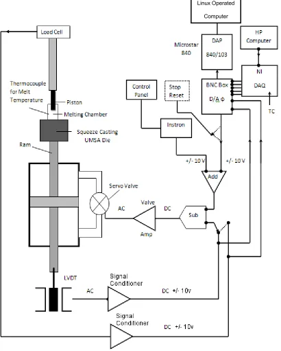
Figure 30 - SC-UMSA test set-up, data recording and data collection devices: main test and data control computer monitor on left, SCXI-1000 at center, and HP system for monitoring temperature of thermocouples at the right. ... 61
Figure 31 - Schematic diagram of SC-UMSA data collection. ... 63
Figure 32 Three Junctions of Thermocouples ... 65
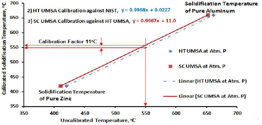
Figure 33 - Relationship between voltages and uncalibrated temperature. ... 70
Figure 34 - Relationship between calibrated data and uncalibrated data. ... 71
Figure 35 - Incorporation of calibration factor in the first derivative of cooling curve of unmodified A356 at 90 MPa for 10 pressure cycles... 71
Figure 36 - Desktop view of four channels labview software for monitoring and recording temperatures of thermocouples in HP computer as shown in a), b), c), and d). ... 73
Figure 37 – SC test samples. ... 77
Figure 38 - Photograph of the HT UMSA Technology Platform. A – Melting and environmental chamber, B - heat exchanging systems, C – Power supply, D – Data acquisition system, E –Desktop computer, X – Water cooling pump. ... 78
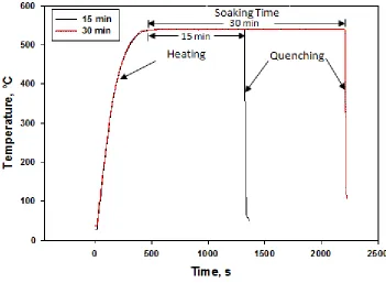
Figure 39 - Solution Treatment heating- quenching curve. ... 81
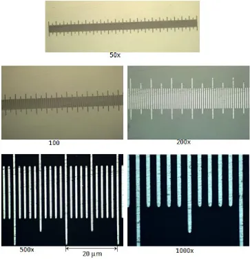
Figure 40 - Calibration scale at different LOM magnification. ... 82
Figure 41 - The As-Cast microstructure showing the dendrite structure and superimposed intersect lines according to the ASTM R-1(Al. 100X) ... 83
xv
Figure 43 - Cooling curve and its first derivative of unmodified A356 at
atmospheric pressure in SC UMSA Platform. ... 90 Figure 44 - Cooling curve and its first derivative of unmodified A356 alloy at 115 MPa pressure with 20 cycles. ... 90 Figure 45 – Comparison of cooling curves of unmodified A356 at different
pressure profiles. ... 95 Figure 46 – Comparison of first derivatives of cooling curves of unmodified A356 at different pressure profiles. ... 96 Figure 47 - Comparison of first derivatives of cooling curves of unmodified A356 at 115 MPa pressure profiles... 97 Figure 48 - Correlation between α-dendrite growth temperature and cyclic pressure of unmodified A356 alloy at different pressure profiles (Appendix E) ... 97 Figure 49 – Cumulative energy of unmodified A356 alloy under 115 MPa with 20 pressure cycles. ... 99 Figure 50 - Correlation between cumulative energy and cyclic pressure of
unmodified A356 alloy at different pressure profiles (Appendix F) ... 100 Figure 51 - Correlation between solidification rate and cyclic pressure of
unmodified A356 alloy at different pressure profiles. ... 100 Figure 52 - Correlation between SDAS or dendrite cell size and average
solidification rate of unmodified A356 alloy at different pressure profiles... 101 Figure 53 - Cooling curves of Sr modified A356 at variable pressure with variable cycles... 103 Figure 54 - First derivatives of cooling curves of Sr modified A356 at variable pressure with variable cycles. ... 103 Figure 55 - Cooling curves of Nano alumina modified A356 at 115 MPa pressure with variable cycles... 106 Figure 56 - First derivatives of cooling curves of Nano alumina modified A356 at 115 MPa pressure with variable cycles. ... 106 Figure 57 - Cooling curves of Sr & Nano alumina modified A356 alloy at 115 MPa pressure with variable cycles. ... 107 Figure 58 - First derivatives of cooling curves of Sr & Nano alumina modified A356 alloy at 115 MPa pressure with variable cycles. ... 108 Figure 59 - LOM Microstructure of UM A356 alloy (Ref. # 31513) solidified in SC die at atmospheric pressure a) Morphology of α-Al Dendrite and Al-Si eutectics, dendrite cell size 23.8 µm b) Main phases are identified , acicular
eutectic Si. ... 111 Figure 60 - SEM Microstructure of UM A356 alloy (Ref. # 31513) solidified in SC die at atmospheric pressure a) Morphology of α-Al Dendrite, Si eutectics,
xvi
Figure 61 - LOM Microstructure of UM A356 alloy (Ref. # 32813) solidified in SC die at 50 MPa/1 pressure a) Morphology of α-Al Dendrite and Al-Si eutectics, dendrite cell size 15.2 µm, b) Main phases are identified , lamellar eutectic Si. ... 112 Figure 62 – Average SDAS or Dendrite Cell Size relationship with Pressure. .... 113 Figure 63 - LOM Microstructure of UM A356 alloy(Ref. # 40113) solidified in SC die at 55 MPa/10 pressure a) Morphology of α-Al cells and Al-Si eutectics, dendrite cell size 11.3 µm, b) Fibrous eutectic Si. ... 113 Figure 64 - LOM Microstructure of UM A356 alloy (Ref. # 40213) solidified in SC die at 60 MPa/10 pressure, a) Morphology of α-Al cells and Al-Si eutectics, dendrite cell size 9.9 µm, b) Fibrous eutectic Si. ... 114 Figure 65 - LOM Microstructure of UM A356 alloy (Ref. # 41913) solidified in SC die at 80 MPa/10 pressure a) Morphology of α-Al Dendrite and Al-Si
eutectics, dendrite cell size 11.9 µm, b) Acicular eutectic Si. ... 114 Figure 66 - LOM Microstructure of UM A356 alloy (Ref. # 41713) solidified in SC die at 90 MPa/10 pressure a) Morphology of α-Al Dendrite and Al-Si
eutectics, dendrite cell size 12.5 µm, b) Acicular eutectic Si. ... 114 Figure 67 - LOM Microstructure of UM A356 alloy (Ref. # 62513) solidified in SC die at 115 MPa/20 cycles pressure a) Morphology of α-Al cells and Al-Si eutectics, dendrite cell size 8.1 µm, b) Fibrous eutectic Si. ... 115 Figure 68 - SEM Microstructure of UM A356 alloy (Ref. # 62513) solidified in SC die at 115 MPa/20 cycles pressure a) Morphology of α-Al cells and Al-Si
xvii
Figure 74 - LOM Microstructure of 0.04 wt% Sr M A356 alloy (Ref. # 51513) solidified in SC die at 100 MPa 10 cycle pressure, a) Morphology of α-Al cells and Al-Si eutectics, dendrite cell size 10.8 µm, b) Fibrous eutectic Si. ... 120 Figure 75 - SEM ultrafine as-cast microstructure of 0.04 wt% Sr M A356 alloy (Ref. # 51313) solidified in SC die at 100 MPa/1 cycle pressure, Morphology of α-Al cells and α-Al-Si eutectics in etched sample, Fibrous dendritic Si. ... 120 Figure 76 - SEM ultrafine as-cast microstructure of 0.04 wt% Sr M A356 alloy (Ref. # 51313) solidified in SC die at 100 MPa/1 cycle pressure, Morphology of α-Al cells and Al-Si eutectics in etched sample, Fibrous dendritic Si. ... 121 Figure 77 – SEM ultrafine as-cast microstructure of 0.04 wt% Sr M A356 alloy (Ref. # 51313) solidified in SC die at 100 MPa/1 cycle pressure, Morphology of α-Al cells and α-Al-Si eutectics in etched sample, Fibrous dendritic Si. ... 121 Figure 78 - SEM ultrafine as-cast microstructure of 0.04 wt% Sr M A356 alloy (Ref. # 51513) solidified in SC die at 100 MPa/10 cycles pressure, Morphology of α-Al cells and Al-Si eutectics in etched sample, Fibrous dendritic Si. ... 122 Figure 79 - LOM Microstructure of 0.015 wt% Sr M A356 alloy (Ref. # 61913) solidified in SC die at 115 MPa 7 cycle pressure a) Morphology of α-Al elongated cells and Al-Si eutectics, dendrite cell size 9.4 µm b) Acicular eutectic Si. ... 122 Figure 80 - LOM Microstructure of 0.015 wt% Sr M A356 alloy (Ref. # 71613) solidified in SC die at 115 MPa 50 cycles pressure a) Morphology of α-Al
fragmented cells and Al-Si eutectics, dendrite cell size 9.3 µm b) Fibrous eutectic Si. ... 123 Figure 81 - SEM Microstructure of 0.015 wt% Sr M A356 alloy (Ref. # 71613) solidified in SC die at 115 MPa/50 cycles pressure a) Morphology of α-Al cells and Al-Si eutectics in polished sample, Fibrous dendritic Si. ... 123 Figure 82 - SEM Microstructure of 0.015 wt% Sr M A356 alloy (Ref. # 71613) solidified in SC die at 115 MPa/50 cycles pressure a-b) Morphology of Si
xviii
and semi-solid α-Al dendrites and Al-Si eutectics, dendrite cell size 11.3 µm, b) Fibrous eutectic Si... 127 Figure 87 - LOM Microstructure of 1 wt% NAMA M A356 alloy (Ref. # 71513) solidified in SC die at 115 MPa 50 cycles pressure a) Morphology of α-Al cells and Al-Si eutectics, dendrite cell size 9.2 µm b) Fibrous eutectic Si. ... 127 Figure 88 - SEM Microstructure of 1 wt% NAMA M A356 alloy (Ref. # 71513) solidified in SC die at 115 MPa 50 cycles pressure a) Morphology of α-Al Cells and Al-Si eutectics in polished sample, b) Ultrafine Si. ... 128 Figure 89 - SEM Microstructure of 1 wt% NAMA M A356 alloy (Ref. # 71513) solidified in SC die at 115 MPa 50 cycles pressure a) Morphology of α-Al
equiaxed cells and Al-Si eutectics in polished sample, b) shrinkage porosity filled with MgO. ... 128 Figure 90 - LOM Microstructure of both 0.015 wt% Sr & 1 wt% NAMA M A356 alloy (Ref. # 72413C) solidified in SC die at atmospheric pressure a) Morphology of α-Al cells & Al-Si eutectics, dendrite cell size 15.2 µm b) Fibrous eutectic Si. ... 132 Figure 91 - LOM Microstructure of both 0.015 wt% Sr & 1 wt% NAMA M A356 alloy (Ref. # 81413) solidified in SC die at 115 MPa 12 cycles pressure a)
Morphology of α-Al cells & Al-Si eutectics, dendrite cell size 9.2 µm b) Fibrous eutectic Si. ... 132 Figure 92 - LOM Microstructure of both 0.015 wt% Sr & 1 wt% NAMA M A356 alloy (Ref. # 62413) solidified in SC die at 115 MPa 20 cycles pressure a)
Morphology of α-Al cells and Al-Si eutectics, dendrite cell size 9.9 µm b) Fibrous eutectic Si. ... 133 Figure 93 - LOM Microstructure of both 0.015 wt% Sr & 1 wt% NAMA M A356 alloy (Ref. # 61713) solidified in SC die at 115 MPa 50 cycles pressure a)
Morphology of α-Al cells and Al-Si eutectics, dendrite cell size 7.6 µm b) Fibrous eutectic Si. ... 133 Figure 94 - SEM Microstructure of both 0.015 wt% Sr & 1 wt% NAMA M A356 alloy (Ref. # 81413) solidified in SC die at 115 MPa 12 cycles pressure a)
xix
Figure 97 - LOM Microstructure of 0.015 wt% Sr M A356 alloy ( Ref. # 71613) solidified in SC die at 115 MPa 50 cycles pressure and Solution Treated at 540ᵒC for 15 min a) Morphology of α-Al Dendrite & Al-Si eutectics, b) Spheroids of eutectic Si and other phases. ... 136 Figure 98 - LOM Microstructure of 0.015 wt% Sr M A356 alloy ( Ref. # 71613) solidified in SC die at 115 MPa 50 cycles pressure and Solution Treated at 540ᵒC for 30 min a) Morphology of α-Al & Al-Si eutectics, b) Spheroids of eutectic Si and other phases. ... 136 Figure 99 - SEM Microstructure of UM A356 alloy ( Ref. # 62513) solidified in SC die at 115 MPa 20 cycles pressure and Solution Treated at 540ᵒC for 30 min a) Morphology of α-Al & Al-Si eutectics, b) Spheroids of eutectic Si and other phases. ... 137 Figure 100 - SEM Microstructure of 0.015 wt% Sr M A356 alloy ( Ref. # 71613) solidified in SC die at 115 MPa 50 cycles pressure and Solution Treated at 540 ᵒC for 30 min a) Morphology of α-Al & Al-Si eutectics, b) Spheroids of eutectic Si and other phases. ... 137 Figure 101 - Image Analysis of Si Spheroids in Solution Treatment for UM and Strontium modified alloy at 540ᵒC for 15-30 min, Comparison of Perimeter of Si spheroids at different soaking time and alloy. ... 138 Figure 102 - Image Analysis of Si Spheroids in Solution Treatment for UM and Strontium modified alloy at 540ᵒC for 15-30 min, Comparison of Area of Si
xx
Figure 110 - Correlation between average SDAS or dendrite cell size and
cumulative energy for modified and unmodified alloys. ... 146 Figure 111 – Correlation between average SDAS or dendrite cell size and average solidification rate for modified and unmodified alloys... 147 Figure 112 – Correlation between SDAS or dendrite cell size and pressure cycles at 115 MPa for modified and unmodified alloys. ... 148 Figure 113 – LOM Microstructure of Alcoa wheel part with 0.015 wt% Sr M A356 alloy solidified at atmospheric pressure in LPDC process and Solution Treated at 540 ᵒC for 5 hours a) Morphology of α-Al Dendrite & Al-Si eutectics, b)
xxi
xxii
xxiii
Figure 169 - Stroke, pressure profile and cumulative energy of Nano alumina modified A356 at 115 MPa with 2 pressures cycles. ... 194 Figure 170 - Cooling curve and its first derivative Nano alumina modified A356 at 115 MPa with 20 pressures cycles. ... 195 Figure 171 - First derivative of cooling curve of Nano alumina modified A356 at 115 MPa with 20 pressures cycles. ... 195 Figure 172 - Cooling curve and pressure profile of Nano alumina modified A356 at 115 MPa with 20 pressures cycles. ... 196 Figure 173 - Stroke, pressure profile and cumulative energy of Nano alumina modified A356 at 115 MPa with 50 pressures cycles. ... 196 Figure 174 - Cooling curve and its first derivative Nano alumina modified A356 at 115 MPa with 50 pressures cycles. ... 197 Figure 175 - First derivative of cooling curve of Nano alumina modified A356 at 115 MPa with 50 pressures cycles. ... 197 Figure 176 - Cooling curve and pressure profile of Nano alumina modified A356 at 115 MPa with 50 pressures cycles. ... 198 Figure 177 - Stroke, pressure profile and cumulative energy of Nano alumina modified A356 at 115 MPa with 50 pressures cycles. ... 198 Figure 178 - Cooling Curve and its first derivative of Sr and Nano alumina
modified A356 at atmospheric pressure. ... 199 Figure 179 - First derivative of cooling curve of Sr and Nano alumina modified A356 at atmospheric pressure. ... 199 Figure 180 - Cooling Curve and its first derivative of Sr and Nano alumina
modified A356 at 115 MPa with 12 pressures cycles. ... 200 Figure 181 - First derivative of cooling curve of Sr and Nano alumina modified A356 at 115 MPa with 12 pressures cycles. ... 200 Figure 182 - Cooling curve and pressure profile of Sr and Nano alumina modified A356 at 115 MPa with 12 pressures cycles. ... 201 Figure 183 - Stroke, Pressure profile and cumulative energy of Sr and Nano
alumina modified A356 at 115 MPa with 12 pressures cycles. ... 201 Figure 184 - Cooling Curve and its first derivative of Sr and Nano alumina
modified A356 at 115 MPa with 20 pressures cycles. ... 202 Figure 185 - First derivative of cooling curve of Sr and Nano alumina modified A356 at 115 MPa with 20 pressures cycles. ... 202 Figure 186 - Cooling curve and pressure profile of Sr and Nano alumina modified A356 at 115 MPa with 20 pressures cycles. ... 203 Figure 187 - Stroke, Pressure profile and cumulative energy of Sr and Nano
alumina modified A356 at 115 MPa with 20 pressures cycles. ... 203 Figure 188 - Cooling Curve and its first derivative of Sr and Nano alumina
xxiv
Figure 189 - First derivative of cooling curve of Sr and Nano alumina modified A356 at 115 MPa with 50 pressures cycles. ... 204 Figure 190 - Cooling curve and pressure profile of Sr and Nano alumina modified A356 at 115 MPa with 50 pressures cycles. ... 205 Figure 191 - Stroke, Pressure profile and cumulative energy of Sr and Nano
xxv
LIST OF APPENDICES
xxvi
LIST OF ABBREVIATIONS/SYMBOLS
A/D, D/A Analogue to Digital, Digital to Analogue
DAP Data Acquisition Processor
DAQ Data Acquisition
HPDC High Pressure Die Casting
HSR High Solidification Rate
HT/ST Heat Treatment/Solution Treatment
HT UMSA High Temperature Universal Metallurgical Simulator and Analyzer
LOM Light Optical Microscopy
LPDC Low Pressure Die Casting
LVDT Linear Variable Differential Transformer
MA Master Alloy (Al-Sr)
MCPT Metal Casting and Post-Processing Technology
NAMA Nano Alumina Master Alloy (MgAl
2O3)
NIST National Institute of Standards and Technology
SC Squeeze Casting
SEM Scanning Electron Microscopy
SDAS Secondary Dendrite Arm Spacing
SR [⁰C/s] Solidification Rate - Average rate of temperature change in the
semi-solid region
SC UMSA Squeeze Casting Universal Metallurgical Simulator and Analyzer
TA Thermal Analysis
TαDENNUC
[⁰C] α- Al Dendrite Nucleation Temperature
TαDENMIN [⁰C] α- Al Dendrite Minimum (Undercooling) Temperature
TαDENG [⁰C] α- Al Dendrite Growth Temperature
TAlSiE, G [⁰C] Al-Si Eutectic Growth Temperature
Ts [⁰C] Solidus Temperature
tαDENG α- Al Dendrite Growth Time
tS Solidus Time
UBC University of British Columbia
UM Unmodified
1
CHAPTER ONE - INTRODUCTION
1.0.
Background
In this competitive automotive industry there is a continuing demand for materials with
improved strength and durability for achievement of weight and cost savings. The
aluminum casting industry responds to these goals through the use of novel technologies
and development of semi-solid processing that result in significant refinement and
modification of microstructural features (phases) including eutectic Si, SDAS and
α-dendrite cell size for the improvement of components’ functional. Alcoa, a leader in the
production of A356 aluminum wheels, which are 35 - 44% lighter compared to the
conventional steel wheels, uses the Low Pressure Die Casting (LPDC) process [1]. The
Metal Casting and Post-processing Technology (MCPT) Group of University of Windsor
collaborated with Alcoa on LPDC technology.
The ALCOA Collingwood Aluminum Wheel Plant used the following processing
parameters for making A356 aluminum wheels with the LPDC process [2]:
Induction melting: maximum temperature 780°C
Degassing and skimming in the temperature range from 760 to 735°C
Sr master alloy (Al-15wt%Sr) for Si modification: 130 to 150 ppm Sr
TiB master alloy (Al-5wt%Ti, 1wt%B) for grain refining: 0.12 to 0.13 wt%Ti;
10 to 30 ppm B
Melt transfer temperature (to the LPDC machine) range from 735 to 705°C
2
Wheel ejection temperature: 470°C
Solution Treatment: temperature range (set point in various zones): 540 to545°C, time: 297 minutes, 70°C water quenching; Artificial aging:
temperature 150°C, time 148 min
There are ample publications on the utilization of Squeeze casting (SC), High Pressure
Die Casting (HPDC) and Low Pressure Die Casting (LPDC) technologies for automotive
cast components, e.g.: transmission cases and road wheels, radiator support, dash panels
etc. However, exploring a novel approach in this area, MCPT group found the SC UMSA
to be a potential process for wheel production, which is very similar to the Die Casting
process as high pressure is applied on the liquid melt in both processes.
The current study shows that commercial LPDC as-cast and heat treated structures of
A356 Al wheels can be significantly improved by using the following methodologies in
SC UMSA Technology Platform keeping similar process parameters [2]:
Melt treatment using commercial Al-10wt.%Sr master alloy and the novel Nano
Alumina Master Alloy, MgAl2O3 (NAMA) individually and combined.
Various pressure profiles (cyclic pressure up to 115 MPa with 1-50 No. of cycles,
amplitude, timing etc.)
Solution treatment (at 540 ᵒC, 15- 30 min) including Quenching at 70ᵒC water and natural aging, no artificial aging.
MCPT Group is involved in the further developing of SC-UMSA Technology Platform’s
physical simulation capabilities for possible merging of the SC and LPDC processes
3
Ph.D dissertations will cover the new technology for the development of new Magnesium
alloy, hypoeutectic and hypereutectic aluminum alloys. Depending on the research
outcome, the new SC technology may be used as an alternative stand alone production
process for advanced, cost effective mass production of low weight components. SC
UMSA Technology Platform including a novel squeeze pin has been being considered for
patenting. The new scientific and applied engineering knowledge needed for rapid
progress in the understanding of the metallurgical phenomena governing SC
technological processes of new class A356 material(s) and cast components is generated
in the scope of this research project.
This thesis will concentrate on the analysis and quantification of the solidification of
squeezed cast A356 Aluminum alloy subjected to high pressure applied in a cyclic
manner between the liquidus and solidus temperature. Applied Pressure on a solidifying
semi solid melt has a great impact on the thermal and microstructural characteristics of
the resulting cast component. The pressure can be applied in a number of ways, such as
high pressure die casting, hot isostatic pressing or squeeze casting. Squeeze casting (SC)
is held to provide the highest mechanical properties of the three. In commercial SC,
pressure is applied in static manner and produces large dendrites. Cyclic pressure
disintegrates the primary phase (long dendrite arm) as well as the secondary phases
(Coarse Si, AlSiFeMg) and produces almost equiaxed α-aluminum cell and ultrafine
dendritic eutectic Si. Solution treatment of this structure goes into spheroidization of Si
particles within a very short soaking time. Therefore, the innovative cyclic pressure was
4
In addition, A356 alloy has high demand in the auto industry due to its excellent
castability and good weldability. It is currently the most popular alloy used in squeeze
casting and semi solid metal processing. A356 has long been the material of choice for
cast aluminum automobile wheels in North America and has become the standard for
most automotive chassis and suspension castings as well. This alloy is used by Alcoa,
Toyota and GKN plc for making automotive wheels through squeeze casting. In other
applications where pressure tightness, and good resistance to corrosion are required,
5
1.2.
Scope of Research
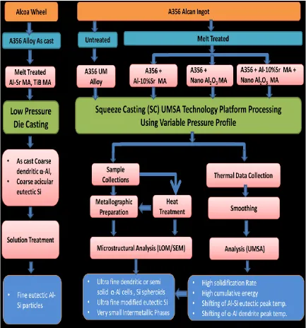
The research is outlined as per the flow chart shown in Fig. 1.
6
1.3.
Objectives
1. To perform a worldwide, comprehensive literature review regarding the A356 alloy; its
processing technologies including Squeeze casting (SC); the effect of pressure profiles
during solidification; master alloys; thermal and metallurgical analysis for material and
process characterization.
2. To determine the methodologies and the calibration scope of thermocouples and the
Data Acquisition System used in SC UMSA Platform.
2.1. HT UMSA Calibration at a very low Solidification Rate (SR) against
National Institute of Standards and Technology (NIST) calibrated data.
2.2. SC UMSA Calibration at a high SR against HT UMSA calibrated data.
3. To design and execute SC UMSA experiments for the development of novel materials
and technology as well as characterization of the solidification process for untreated and
treated A356 melts/samples subjected to variable pressure profiles (Pressure up to 115
MPa, 1-50 cycles).
3.1. To determine a suitable pressure profile for the untreated and the melt-
treated A356 using nano-Al2O3 and Sr Master Alloys as well as combined (Sr and
Nano Alumina) Master Alloys rendering semi-solid α-Al cells and ultra fine Si in
the as-cast SC test samples.
3.2. To determine Solution Treatment (ST) parameters rendering a significantly
7
4. To understand the effect of experimental conditions on the solidified structure and
8
CHAPTER TWO - LITERATURE REVIEW
2.1.
Aluminum and Aluminum Alloys
2.1.1.
Aluminum
Pure aluminum is a soft, lightweight metallic element. It is the second most plentiful
metallic element on earth. It became an economic competitor in engineering applications
at the end of the 19th century [4]. The properties of aluminum that make this metal and
its alloys the most economical and attractive for a wide variety of uses are appearance,
light weight, fabricability, physical properties, mechanical properties, and corrosion
resistance. Aluminum has a density of only 2.7 g/cm3, which is approximately one-third
of steel (7.83 g/cm3), copper (8.93 g/cm3), or brass (8.53 g/cm3). It can display excellent
corrosion resistance in most environments, including atmosphere, water (including salt
water), petrochemicals, and many chemical systems if optimized in terms of chemical
composition and heat treatment [7-9].
2.1.2.
Aluminum Alloys
Aluminum alloys are divided into two major categories based on the processing
technology and the primary mechanism of property development: Cast Aluminum and
wrought aluminum alloys [7-9]. Wrought alloys are those obtained by working on ingots
of particular forms, which can be affected by rolling, extruding, drawing or forging. Cast
alloys are those for which ingots are melted and poured into moulds having the shape of
9
2.1.3.
Alloy Designation of Cast Aluminum Alloys
A system for designating aluminum and aluminum alloys that incorporate the product
form (wrought, casting, or foundry ingot), are covered by American National Standards
Institute (ANSI) standard H35.1. The Aluminum Association is the registrar under ANSI
H35.1 with respect to the designation and composition of aluminum alloys in the United
States [4]. The Aluminum Association has established a system of nomenclatures to
divide the alloys according to a number of criteria, including chemistry and processing
(i.e. cast vs. wrought alloys). This thesis will discuss only the cast aluminum alloys. The
cast aluminum alloys families are shown in Table 1 [4].
Table 1 - Cast Aluminum Alloy Families [4].
Code Description
1xx.x Controlled unalloyed (pure) compositions
2xx.x Copper as major alloying element, other elements may be included
3xx.x Silicon as major alloying element, other elements (e.g. Cu or Mg) included
4xx.x Silicon as principal alloying element
5xx.x Magnesium as principal alloying element
6xx.x Currently unused
7xx.x Zinc as principal alloying element, other elements (e.g. Cu, Cr, Mn or Mg) included
8xx.x Tin as majorly alloying element
9xx.x Currently unused
Cast alloys are described by a three digit system followed by a decimal value. In this
10
family of alloys. The ‘x’ following the decimal point refers to alloy composition limits
and indicates either cast composition limits (.0) or ingot composition limits (e.g. .1 or .2).
Furthermore, a letter added as a prefix to a code indicates a specific restriction to the
alloy such as a limitation on impurity elements between primary and secondary alloys
[3]. For an instance, differences between designations and the alloys are compared in
Table 2 between two alloys, 356.0 and A356.0. Also, some common industrial aluminum
alloys are shown in Table 3.
2.1.4.
Importance of Al-Si Alloys
Among all commercial aluminum casting alloys, Al-Si alloys are the most important ones
mainly because of their excellent casting characteristics. The most attractive reasons for
which Al-Si alloys are widely used are their inexpensiveness and availability. Addition of
Si to pure aluminum imparts high fluidity, good feeding characteristics, low shrinkage
and good hot cracking resistance [4]. The high strength to weight ratio is another
important characteristic. While the volume of most metals (including Al) shrinks
substantially on solidification, two phase Al-Si alloys contract relatively less. These are
the only Al alloys that are not prone to hot-tearing during solidification. Silicon has a
density of 2.3 g/cc, which is very close to that of aluminum, and thus is one of the few
elements which may be added to aluminum without affecting the light weight of the
alloy. For a specific application, the selection of an alloy depends on its castability, the
casting process, the required mechanical and physical properties and the end use of the
casting. The properties of Al-Si alloys make them very popular in various applications
including the automotive, aerospace and defense industries.
11
Table 2 - Comparison of Two Alloy Designations and Their Chemistries [3].
Code Composition (Trace elements excluded)
356.0 6.5-7.5 Si, 0.25 Cu max, 0.20-0.45 Mg, 0.35 Mn max, 0.60 Fe max, 0.35 Zn max, 0.25 Ti max
A356.0 6.5-7.5 Si, 0.20 Cu max, 0.25-0.45 Mg, 0.10 Mn max, 0.20 Fe max, 0.10 Zn max, 0.20 Ti max
Table 3 - Some Common Industrial Alloys of Aluminum [8].
Alloy types Alloy Characteristics
Hypoeutectic Al-Si casting alloys (less than 10% Si)
Standard automotive grades of A356 and 359 Aerospace and structural alloys: C355 and 357 High-purity alloys: B356, C356 and E357, F357 Low strength, high ductility, binary alloys: 443 and 444 Die-casting alloys: 360 and
Eutectic Al-Si casting alloys (greater than 10% and less than 12.6% Si)
High-purity near-eutectic Al-Si alloys: 413.X and A413.x For thin wall intricate, high integrity die-cast parts
requiring ductility and consistent castability and pressure tightness A365, Aural™-2 and Aural™-3
Hypereutectic Al-Si casting alloys (greater than 12.6 % Si)
For wear resistance castings: A390.1
Al-Cu alloys High strength and ductility alloy with fracture toughness:
A206, B206. High temperature alloy 242
Al-Si-Cu alloys
Automotive and Aerospace alloys: 319, 354, A355, and C355. Specialty diesel engine cylinder head alloys by inquiry only.
2.1.5.
Al-Si Alloy System
Al-Si binary alloy is a eutectic system with the eutectic composition at 12.6 wt. % Si and
12
The two phases in equilibrium below the eutectic temperature will be Al solid solution
(solid solution of Si in Al) and pure Si. The solid solubility of Si in Al at 577 ᵒC is 1.65%.
However, rapid quenching from the liquid in non-equilibrium stage raises the solubility
up to 16% Si and shifts the eutectic point up to 17% Si [9]. Silicon reduces the thermal
expansion coefficient, increases corrosion and wear resistance and improves casting and
machining characteristics of the alloy. As the Al-Si alloy solidifies, the primary alpha
aluminum forms and grows in dendrites. When the eutectic point is reached, the eutectic
Al-Si phases nucleate and grow until the end of solidification. The alloys to the left of the
eutectic composition are referred to as hypoeutectic alloys and those to the right as
hypereutectic alloys [12-13].
At room temperature, hypoeutectic alloys consist of a soft and ductile primary aluminum
phase and a hard brittle eutectic silicon phase. In hypoeutectic alloys, the silicon varies
between 5.5 and 10.5%, and primary aluminum is the first phase to solidify. The
microstructure consists of primary aluminum dendrites, eutectic Si and AlSiFe
intermetallic phases. Eutectic alloys contain 10.5 to 12.5% silicon and have
microstructures consisting mainly of aluminum - silicon eutectic. In hypereutectic alloys
containing more than 12.6% silicon, the first phase to solidify is the primary silicon
phase. Hypereutectic alloy usually contains coarse, primary silicon cuboids as well as
angular eutectic silicon phase. These alloys having a distribution of coarse silicon
cuboids provide excellent wear resistance [11].
Although binary Al-Si alloys show excellent casting characteristics, the addition of Mg,
Cu and Zn makes the alloys heat treatable, providing the means to enhance their
13
Figure 2 - Al-Si Binary phase diagram [4], [6].
Figure 3 - Part of the Al-Si Binary phase diagram [10].
less than about 0.75%, because increased additions impair fluidity and feeding. The most
common primary aluminum casting alloys in the Al-Si-Mg family are Al-7Si-0.3Mg
(A356) and Al-7Si-0.6Mg (A357) [10-14]. Alloy A357 is similar to A356 but has higher
14
specifically for die casting and, as such, contain more silicon and higher iron and allow
more impurities than A356 [13].
2.1.6.
Mechanical Properties of Al-Si Alloys
The mechanical properties of an Al-Si cast alloy are mainly governed by the grain size,
secondary dendrite arm spacing (SDAS), α-dendrite cell size and the size, shape and
distribution of the eutectic silicon particles, as well as the morphologies and amounts of
intermetallic phases present [3, 6, 16]. The amount of aluminum dendrites in
hypoeutectic Al-Si alloys is mainly dependant on solidification parameters like applied
pressure, cooling rate, casting process etc., and its control can improve mechanical
properties of the finished products. Further, the desirable mechanical properties in these
alloys can also be obtained by controlling chemical composition and process parameters
during melting, casting and heat treatment [13, 17].
The amount of silicon added can depend on the casting process being used. Slow cooling
processes such as sand and investment casting can use alloys with silicon compositions of
5% to 7%, while fast cooling processes, such as squeeze casting and die casting, silicon
contents are used from 8% to 12%. The latter alloy has a higher fluidity and lower
melting point than the former. The higher silicon content, approaching the eutectic
composition of 12.6%, decreases the solidification range of the alloy, reducing the chance
of cold shuts and incomplete filling in the faster cooling processes, when cast at the same
temperature [3, 13-14, 16]. These advantages result in most common commercial casting
alloys containing a significant proportion of silicon. Other alloying additions are made to
improve the mechanical properties of the casting, or are present as impurities, either
15
2.1.7.
Effect of Minor Common Elements Present in Al-Si Alloys
Alloying elements are selected based on their effects and suitability. The alloying
elements may be classified as major and minor elements, microstructure modifiers or
impurities; however the impurity elements in some alloys could be major elements in
others. Apart from the silicon, there are some common minor elements (e.g. Copper,
Magnesium, Manganese) added to the alloy that also have significant effect on the
mechanical properties of Al-Si alloys, while iron is treated as common impurity. A
summary of those element and their effects are discussed below [3-4, 11, 13]. Silicon
modifying elements (Strontium, Sodium, and Antimony) will be discussed in section
2.1.8.
Copper
Generally copper increases the mechanical properties of the as-cast and heat-treated alloy
through solution strengthening and precipitation strengthening. Copper additions also
reduce corrosion resistance, decrease castability and slightly reduce ductility [4].
Magnesium
A small addition (up to 0.1%) of magnesium causes increases in tensile and fatigue
strength, and large decreases in ductility and impact strength. The reduction in ductility
and impact properties is due to the formation of Mg2Si precipitates in the bulk metal. In
addition, Shilvock [15] found that the presence of magnesium could detrimentally affect
Si modification of Al12Si alloy.
Iron
Iron is usually present in aluminium alloys as an impurity. If the level of iron
16
are formed [15]. The β phase is associated with plate-like precipitates containing
aluminium, silicon and iron, which are detrimental to the mechanical properties. Iron
increases hot tear resistance and reduces die soldering but decreases flowability and
feeding characteristics [15].
Manganese
Manganese is reported to have a little effect on the mechanical properties of cast
aluminium silicon alloys [14]. However, Shilvock [16] reports a number of conflicting
studies which show that, in the absence of iron, manganese will either slightly increase or
decrease tensile strength and decrease ductility. Shilvock concludes that tensile strength
gains from manganese are only seen when strontium is used as a silicon modifier, and the
presence of manganese is detrimental to ductility in all cases [16]. In the presence of
significant iron (>0.5%) manganese is added to create αAl(Mn,Fe)Si "Chinese script"
precipitates instead of more embrittling βAlFeSi plates [15].
2.1.8.
The A356 Alloy and Silicon Modification
Aluminum A356 alloy is a hypo-eutectic alloy. It is one of the most widely used casting
aluminum alloys in the automotive and aerospace industries due to its excellent
mechanical strength, ductility, hardness, fatigue strength, pressure tightness, fluidity, and
machinability [3]. The nominal chemical composition [3] of A356 alloy is (6.5-7.5)wt%
Si, (0.25-0.45)wt.% Mg, 0.10wt.% Mn max, 0.20wt.% Fe max, 0.10 wt.% Zn max,
0.20wt.% Ti max. The designation of this alloy is different in other countries, and it is
known as LM25 in the Great Britain, AC4C in, Japan, L-2651 in Spain and A19 in
17
reaction. It has about 50 vol. % eutectic phases. The final microstructure is mainly
determined by the eutectic reaction [17].
The role of silicon in this alloy is to improve castability, resistance to hot tearing, and
reduce the casting’s susceptibility to shrinkage defects, as silicon increases in volume on
solidification [18]. Though Si needles strengthen the α-aluminum matrix, Si lowers the
ductility [19] of the material significantly. At low solidification rates, silicon appears as
coarse acicular flakes that serve as crack initiators, causing the material susceptible to
fracture in a brittle mode and reduce its fatigue life [20-21]. These needles work as major
stress raisers in Al-Si alloys and need to be converted to a fibrous form to minimize the
stress risk [20, 22].
In unmodified A356 alloys, the eutectic silicones are found in the form of large plates
with sharp ends as acicular type. Silicon crystals in eutectic mixture grow in a fetched
manner as shown in Fig. 4. Lamellar silicon is a finer version of the coarse, acicular
structure, while fibrous silicon has a fine, apparently globular, morphology. "Silicon
modification" is a method in which inoculants are added in the form of master alloys to
A356 melt in order to promote the formation of a fine and fibrous eutectic silicon
structure during the solidification process. Eutectic modification refers to the transition
from acicular to fibrous or lamellar silicon. The modification of the eutectic silicon to a
finer and more rounded structure improves the mechanical properties of A356 alloy
considerably [20-21, 23] including a slight increase in UTS and a large increase in
ductility [21-22, 24-28]. According to the widely accepted impurity induced twinning
theory proposed by Lu and Hellawell [29-30], Na or Sr (modifier) is adsorbed on the
18
forced twinning of the silicon crystal and thus resulting in enhanced branching and a
fibrous microstructure (Figure 5).
Figure 4 - Silicon crystals in a unmodified A356 alloy sample, SEM pictures after deep etching [10].
Figure 5 - Silicon crystals in a modified A356 alloy sample, SEM pictures after deep etching [10].
Three well-known eutectic modification methods were found in the literature namely,
chemical modification [26, 30-38], quench modification [38-41], and super-heating
modification [40]. Recent additional modification methods mentioned in the literature are
namely, melt thermal treatment [41], ultrasonic vibration of melt [17] and mould
vibration during solidification. A significant modification in eutectic silicon was also
claimed by users of those methods [42].
Among all of the methods, chemical modification is most popular in the industry with the
addition of trace-levels of several elements, such as sodium, antimony, potassium,
a) 100x b) 1000x
b) 1000x
19
calcium, strontium, and barium. The addition of strontium is most widely used due to
long lasting effect in the melt [45-46]. A comparison of silicon morphology in
unmodified, Sr modified and Antimony modified hypoeutectic Al-Si alloy is shown in
Figure 6 [44].
Figure 6 - Comparison of the silicon morphology in (a) unmodified, (b) Sr-modified (300ppm Sr) and (c)
Sb-modified (2400ppm Sb), hypoeutectic Aluminum–Silicon alloys [44].
2.1.9.
Chemical Modification and Mechanical Characteristics
2.1.9.1.
Strontium
Strontium has become very prominent as a major Si modifier in the foundry industry.
Pure strontium can be used as a modifier, but is commonly added in the form of
Al-10wt%Sr master alloy to minimize reactions with air and water vapor [25, 47-48].
Backerud et al. [10], reported that strontium addition in a A356 alloy changed the
morphology of the eutectic silicon crystals from large flakes into a fibrous structure
20
the nucleation and growth process of eutectic Si by lowering the nucleation and
α-dendrite growth temperature of the alloy by approximately 10 ᵒC [10].
A superior modification of the silicon eutectic phase in Al-Si alloys was found in the
range of 0.007% [35], to 0.017% strontium [45, 49] despite a wider range of
concentrations found in industry from 0.015 to 0.050% and beyond. However, it is
usually accepted that modification of the eutectic Si phase occurs at strontium levels
higher than 150 ppm (0.015%) [48]. As the amount of strontium in the melt increases, the
level of modification also increases [51-52]. The optimum modification level depends
mainly on the cooling rate of the casting [18] and on its chemistry [51].
Over addition of strontium may negatively affect castability of the alloy [23]. Two
discrete effects are associated with the strontium over modification [46]. The first one is
coarsening of the silicon structure and the reversion of the fine fibrous silicon to an
interconnected plate form. The second one is the presence of strontium containing
intermetallic phases in the microstructure, such as Al2SrSi2 or Al4SrSi2 [25, 48] . Both of
these effects can reduce the mechanical properties of the alloy, causing them to revert to
values more typical of unmodified alloys. Surplus strontium in the melt, can also form
Al2Si2Sr particles and reduce the modification properties [50].
2.1.9.2.
Sodium
Sodium could be used in aluminium silicon alloys as a modifier of the eutectic phase.
Addition of small quantities of Sodium could greatly improve mechanical properties of
cast aluminium silicon alloys by refining the coarse plates of eutectic silicon into a finely
over-21
modification, reducing the gains in strength and ductility achieved from the eutectic
refinement [14]. Over-addition of sodium has been shown to decrease tensile strength and
elongation from the peak values. Sodium has a high rate of loss in the melt due to the
high vapour pressure of liquid sodium. The time interval window for an acceptable level
of modification of a eutectic aluminium-silicon alloy by sodium is short compared to
strontium, e.g. approximately 20 minutes to 50 minutes [14].
Figure 7 - Microstructure at the end of solidification (unquenched): a) unmodified, b) 0.008% Na and c) 0.017%
Na [52].
Na produces the finest modified structures at the lowest Na concentration, so it
might be expected that sodium is the ideal modifier, but factors such as ease of
dissolution, vapor pressure, and stability in the melt can limit its use [46]. The addition
of sodium is accompanied by a violent reaction which can result in increased hydrogen
levels. Typical retained sodium levels for effective modification are in the range
0.005-0.01% [47-48]; additions of Na over 0.02%. As shown in Figure 7 over modification
with Na leads to a coarsening of the Si [52] and is associated with bands of primary
aluminum [46]. Sodium levels in the melt are difficult to control, as it is difficult to
accurately add it to the melt, and it fades rapidly. Re-modification is performed as
22
2.1.9.4.
Antimony
Antimony is very stable in the melt with virtually no losses (even after
re-melting), so extra additions are not required. Sb is effective in amounts of 0.1-0.4% [46].
Although it was once used fairly extensively for commercial applications in Europe and
Japan, it is now used less, primarily because recycling metal containing Sb is difficult. In
addition, Sb can react with hydrogen dissolved in the liquid aluminum to form deadly
stibine gas (SbH3) [46].
2.1.10.
Levels of Si Morphology Modification
The level of Si modification of an A356 alloy appear to have a strong reliance not
only on the strontium content, but mainly on the applied pressure during solidification,
solidification rates and post solidification solution heat treatments [19]. The modified
microstructures contain fine fibrous silicon. These fibres appear to be small individual
particles on a conventional polished surface, but etching away the aluminum shows that
they are connected in a coral or a sea weed like structure [10].
Two standards to determine the level of modification of silicon particles have been
suggested in the literature, namely: the AFS Si Modification Standard and MCPT
Quantitative Si Modification Level [18], [54]. The first method can only be used for
Al-Si hypoeutectic alloys and the second one for both hypo and hypereutectic alloys. In the
first method, the determination of the level of modification of silicon is carried out by
comparing micrographs of the test sample with the AFS wall chart by visual observation.
These results could be biased and could have observational error. It does not take
23
In the second method quantitative assessment of SiML is introduced by MCPT group at
the University of Windsor. Jiang and Sokolowski [56] developed a quantitative
methodology of assessing AFS Si partic1e modification using a Leica Q550IW Image
Analysis system. Later on Bhowmik and Alam expanded the quantitative Image analysis
of Si under the supervision of Dr. J.H. Sokolowski [59-60]. Six candidate criteria (length,
width, perimeter, equivalent diameter, area and aspect ratio) were assessed, based on their
ability to differentiate between the Si modification levels [56].
2.1.11.
The Nano Alumina Master Alloy (NAMA)
Despite having traditional individual master alloy for grain refinement and silicon
modification, materials scientists have been working to develop a master alloy that will
serve the purpose of both grain refinement and modification of secondary phases
including eutectic Si. The University of British Columbia
(
UBC) developed theMagnesium Matrix Composite (MMC) by using Baikowski polishing nano Alumina
powder (40 nanometer particle size) as reinforcement materials known as Nano Alumina
Master Alloy (NAMA). This master alloy contains 93% pure magnesium and 7% nano
Alumina powder. It was fabricated by using a unique method for dispersion of nano
Alumina ceramic particles, throughout the volume of liquid alloy melt, to induce
heterogeneous nucleation sites. These particles are wettable by the melt due to the unique
method of their surface modification [57].
Fig. 8 shows the particles remain suspended in the melt for an extended period of time
due to nano particle size and a negligible sedimentation force while Fig. 9 shows an
24
thermodynamically stable in the melt, this novel technology provides much needed time
flexibility during melt holding, processing and casting operations. S. Bhowmik [57]
reported a 15% reduction in SDAS of Al-Si-Cu alloy after adding 2% Nano alumina MA.
He also reported that NAMA alloy has a high ability to modify silicon particles of 328
aluminum alloy. A. Alam [58] reported that using 1.0-2.0 wt.% Nano Alumina MA in
A356 alloy showed (Figures 10 - 11) a high level of Silicon Modification and Grain
Refinement with 2.0wt% being the most effective level.
Figure 8 - Higher magnified SEM micrographs showing the typical microstructure of (a) the semi continuous
MgO layer (b) Detached MgO particles and the Mg channel in the NAMA [57].
Figure 9 – LOM Micrographs shows improved structure of Nano Alumina Master Alloy developed by
25
Figure 10 - LOM micrographs of As-Cast A356 test sample at two different locations from the chilling end after
addition of 1.0 wt. % NAMA (a) 20 mm (b) 50 mm [58].
Figure 11- LOM micrographs of As-Cast A356 test sample at two different locations from the chilling end after
addition of 2.0 wt. % NAMA (a) 20 mm (b) 50 mm [58].
As reported by A. Alam in his master thesis, the preliminary results indicated an
unprecedented high level of refinement and modification of the primary and secondary
phase. Metallurgical analysis of the melt treated with the new master alloy indicated that
during the cast test sample solidification process, the ceramic particles did serve as
heterogeneous nucleation sites for all the phases including eutectics that were formed at
![Table 1 - Cast Aluminum Alloy Families [4].](https://thumb-us.123doks.com/thumbv2/123dok_us/1404443.1173082/36.612.106.543.349.638/table-cast-aluminum-alloy-families.webp)
![Table 8 - Polynomial Coefficients for Binary Al-Xi alloys [58].](https://thumb-us.123doks.com/thumbv2/123dok_us/1404443.1173082/75.612.105.542.93.447/table-polynomial-coefficients-binary-al-xi-alloys.webp)