EVALUATION OF LONG TERM CORE COOLING CAPABILITY FOR
THE APR1400 CONSIDERING LOCA-GENERATED DEBRIS
Jeong Kwan Suh1, Sun Guk Kwon1, Jae Yong Lee2, Hyoung Kyu Cho3, and Goon Cherl Park3
1
Senior Researcher, KHNP Central Research Institute, Republic of Korea
2
General Manager, KHNP Central Research Institute, Republic of Korea
3Professor of Department of Nuclear Engineering, Seoul National University, Republic of Korea
ABSTRACT
Following a postulated loss-of-coolant accident (LOCA), a portion of the particulates, fibrous and chemical debris may be ingested into the reactor coolant system (RCS). This debris could deposit on fuel assembly and thereby affect long-term core cooling (LTCC) while recirculating coolant from the containment sump. To address this safety issue, an evaluation of LTCC capability for the advanced power reactor (APR) 1400 was performed using a RELAP5/MOD3.3 code.
To simulate the core blockage in the RELAP5/MOD3.3 model, it was assumed that the pressure drops obtained from the in-vessel downstream effect tests of the APR1400 occur at the core inlet during a hot-leg break or a cold-hot-leg break of double ended guillotine. The effect of crud and chemical deposition were considered to evaluate the decay heat removal capability when LOCA-generated debris is deposited on a fuel cladding. In addition, full core blockage except for one fuel assembly during a cold-leg break of double ended guillotine was simulated to investigate the limiting decay heat removal capability.
The analyses results showed that sufficient liquid can enter the core when core blockage occurs by the LOCA-generated debris, and the peak cladding temperature was maintained below the acceptance criteria of 700 K. It was concluded from this evaluation that the LTCC capability of the APR1400 is maintained in the presence of LOCA-generated debris.
INTRODUCTION
The APR1400 containment building is designed to facilitate core cooling in the event of a postulated LOCA. The cooling process requires water discharged from the break and containment spray to be collected in an in-containment refueling water storage tank (IRWST) sump for recirculation by the emergency core cooling system (ECCS) and the containment spray system (CSS).
Typically, an IRWST sump contains strainers in series that protect the ECCS components from debris washed into the sump. During ECCS circulation operation following a LOCA event, the strainers collect fiber and particulates preventing them from being ingested into the ECCS and the CSS flow paths. Nonetheless, a portion of the particulates and fibrous material may still be ingested into the ECCS and, subsequently, into the RCS.
Concerns have been raised about the potential for debris ingested into the ECCS to deposit on the fuel assembly and thereby affect LTCC while circulating coolant from the IRWST sump. This issue is collectively identified as United States Nuclear Regulatory Commission (U.S.NRC) generic safety issue (GSI)-191, specifically in-vessel downstream effects.
23rd Conference on Structural Mechanics in Reactor Technology Manchester, United Kingdom - August 10-14, 2015 Division V
(Andreychek et al., 2011) and submitted it to the U.S.NRC. This report describes the WCOBRA/TRAC analyses which were performed to demonstrate that adequate flow is provided and redistributed within the core to maintain LTCC. A bounding evaluation was performed, using limiting assumptions, to evaluate the consequences of core inlet blockage on LTCC. The blockage was assumed to deterministically occur and is not representative of actual plant conditions. Westinghouse performed two analyses which were calculated with core inlet blockage of 82% and 99.4%, respectively. Simulation results showed that sufficient liquid can enter the core to remove decay heat once the plant has switched to sump recirculation with up to 99.4% blockage at the core inlet.
Debris-generated core blockage scenarios during LOCAs using a RELAP5-3D were studied by Vaghetto and Hassan (2013). Simulations were performed to analyze the behavior of the system during a cold-leg break and a hot-leg break, assuming that break sizes are 2-in., 6-in., and a double-ended guillotine as representative cases for small, medium and large break sizes, respectively. The analyses results identified the cold-leg scenarios for medium and large break sizes as the most critical, under a full core and core bypass blockage condition. A lower level of conservatism in the core blockage was assumed for additional cases simulated with the vessel–3D core model for the medium break in cold-leg scenario.
Experiments on pressure drops through LOCA-generated debris deposited on a mock-up fuel assembly were performed by Suh et al. (2015) to resolve the downstream effect concerns in the APR1400. Four tests were run to evaluate hot-leg break conditions with a four safety injection (SI) flow rate varying particle to fiber (P/F) ratios of 0.5, 1, 2, and 10. Seven tests were run to evaluate cold-leg break conditions with a core boil-off rate at 700 seconds after LOCA with varying P/F ratios of 1, 10, 20, 30, 40, 50, and 60. The maximum pressure drop recorded under the hot-leg break condition was 19.4 kPa when the P/F ratio was 1, and under the cold-leg break condition was 3.85 kPa when the P/F ratio was 50.
However, the conservatism and assumption of evaluation needs to be verified by using experimental data. In this study, an evaluation of LTCC capability for the APR1400 was performed using a RELAP5/MOD3.3 code. To simulate the core blockage in the RELAP5/MOD3.3 model, it was assumed that the pressure drops obtained from the in-vessel effect tests of the APR1400 occur at the core inlet during a hot-leg break or a cold-leg break of double ended guillotine. The effect of crud and chemical deposition were considered to evaluate the decay heat removal capability when LOCA-generated debris is deposited on a fuel cladding. In addition, full core blockage except one fuel assembly during a cold-leg break of double ended guillotine was simulated to investigate the limiting decay heat removal capability.
RELAP5/MOD3.3 MODEL DESCRIPTION
Best estimate system code of RELAP5/MOD3.3 was used to analyze the effects of debris ingested into the RCS and core during a recirculation mode. For the evaluation of the effects of blockage at the core inlet, the forward k-loss coefficient was ramped at the core inlet to simulate blockage due to debris buildup. RELAP5/MOD3.3 simulations were run to the beginning of recirculation (calculated to be 700 seconds) at which point the ramping of the friction factor took place. Note that the core inlet flow blockage occurring at 700 seconds from the start of circulation is conservative and was modeled in such a manner to perform a bounding calculation. After the core inlet resistance was increased, the RELAP5/MOD3.3 simulations were run out to 1,800 seconds to show the flow rate supplied to the core would be sufficient to remove decay heat and maintain LTCC.
Assumptions
and 1×10⁴ for the cold-leg break in all core channels which simulates the pressure drops obtained from the in-vessel effect tests of the APR1400. The core bypass flow channel was also simulated to have pressure drops obtained from the in-vessel effect tests. Figure 1 shows the core channel noding used in the Case-1.
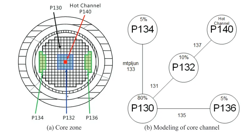
The second case (Case-2) modeled blockage at the core inlet by ramping the value of k-factor up to 1×10⁹ in all core channels, except one fuel assembly, which produces a total coolant blockage at the applied channel under the cold-leg break. The flow path from the lower plenum to the core bypass channel was also assumed to have a total coolant blockage. Figure 2 shows the core channel model used in the Case-2.
23rd Conference on Structural Mechanics in Reactor Technology Manchester, United Kingdom - August 10-14, 2015 Division V
(a) Core zone (b) Modeling of core channel
Figure 2. Core channel model.
Nodalization and Model Description
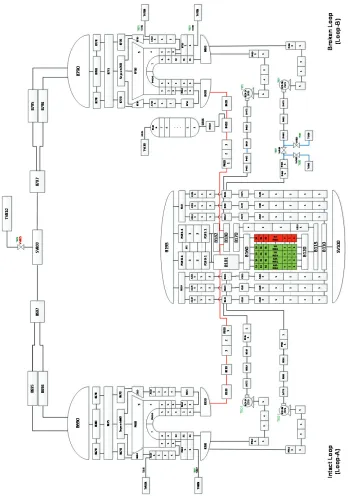
The RELAP5/MOD3.3 nodalization of the APR1400 is described here for the calculation of core inlet blockage. The RELAP5/MOD3.3 nodalization consists of vessel nodalization, core nodalization, and RCS loop nodalization, as shown in Figure 1. The core divided into five sub-channels to simulate the effect of partial core inlet blockage, and the cross flow between the sub-channels was considered. The other components in the RELAP5/MOD3.3 input model: reactor vessel, pressurizer, steam generators, cold-legs and hot-legs were modelled, as shown in Figure 1. Table 1 shows the steady state analysis results for the multi channel model with clean inlet condition.
For simulation of full core blockage except one fuel assembly under the cold-leg break, the channel P130, P132, P134, and P140 in Figure 2 were assumed to be blocked, and the area of junction J135 was assumed to be reduced to that of the one fuel assembly.
During a cold-leg break of double ended guillotine, the ECCS will spill into containment, which decreases the driving head of core flow to a minimum. However, the debris that reaches the RCS lower plenum and core inlet for a cold-leg break will be substantially lower than the debris that reaches the core for a hot-leg break. During a double ended hot-leg break, no spilling of ECCS occurs. Therefore, an additional driving head from the build-up of liquid level in the downcomer and in the steam generator tubes to the spillover elevation is present.
However, the higher flow rates also result in faster debris build-up, and because there is more debris available to accumulate, the hot-leg break represents the conservative case in terms of debris load. To create the worst possible scenario, the limiting break case for modeling purposes will be a modified double ended cold-leg break, i.e., limiting flow at the core inlet, combined with faster debris buildup time that occurs for a high flow hot-leg break.
Deposition on Fuel Cladding
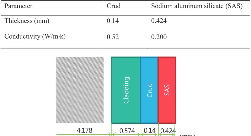
on the fuel cladding. The limiting parameters described in Table 2 were used for the thickness and the thermal conductivity suggested in the WCAP-16793 (Andreychek et al., 2011).
Table 1: Simulation results of the steady state condition.
Parameter Reference value Calculated value
Reactor power (MWt) 3983.3 3983.3
PZR pressure (MPa) 15.51 15.51
PZR level (m) 3.3 3.3
RCS flow rate (kg/sec) 10656.0 10656.0
RCS Tavg (K) 580.3 580.3
SG Pressure (MPa) 6.89 6.89
Table 2: Parameters simulating LOCA-generated debris.
Parameter Crud Sodium aluminum silicate (SAS)
Thickness (mm) 0.14 0.424
Conductivity (W/mຘk) 0.52 0.200
&
OD
GGL
Q
J
&
UX
G
6$
6
(mm) Figure 3. Debris deposition model on fuel cladding.
SIMULATION RESULTS
The thermal hydraulic behavior of the reactor core during a hot-leg break or a cold-leg break of double ended guillotine was evaluated for 1,800 seconds. The first phase of the LOCA transient calculation was carried out for 700 seconds. In the second phase, the partial inlet blockage model adopted for the core inlet and the chemical deposition model on fuel cladding were activated from 700 seconds to 1,800 seconds.
23rd Conference on Structural Mechanics in Reactor Technology Manchester, United Kingdom - August 10-14, 2015 Division V
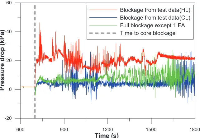
blockage except one FA are about 5.62 kPa during 800 ~ 900 seconds. Figure 4 implies that the assumption of full blockage except one FA gives conservative results compared with test results.
600 900 1200 1500 1800
Time (s) -20 0 20 40 60 P re s s u re d ro p ( k P a )
Blockage from test data(HL) Blockage from test data(CL) Full blockage except 1 FA Time to core blockage
Figure 4. Pressure drops at average channel (P130).
Figure 5 shows total inlet flow rate including core bypass flow when the core blockage simulating test data and full blockage except one FA occurs. The flow rates simulating test data are higher than those of simulating full blockage except one FA. The inlet flow of channel P136, whose area was reduced to one FA area, was abruptly increased after the other channels were blocked by the fibrous debris, as shown in Figure 6.
600 900 1200 1500 1800
Time (s) -3000 -2000 -1000 0 1000 2000 3000 M a s s f lo w r a te ( k g /s )
Blockage from test data(HL) Blockage from test data(CL) Full blockage except 1FA Time to core blockage
600 900 1200 1500 1800 Time (s) -200 0 200 400 M a s s f lo w r a te ( k g /s )
Full blockage except 1FA Time to core blockage
Figure 6. Flow rate at the channel simulating one FA area.
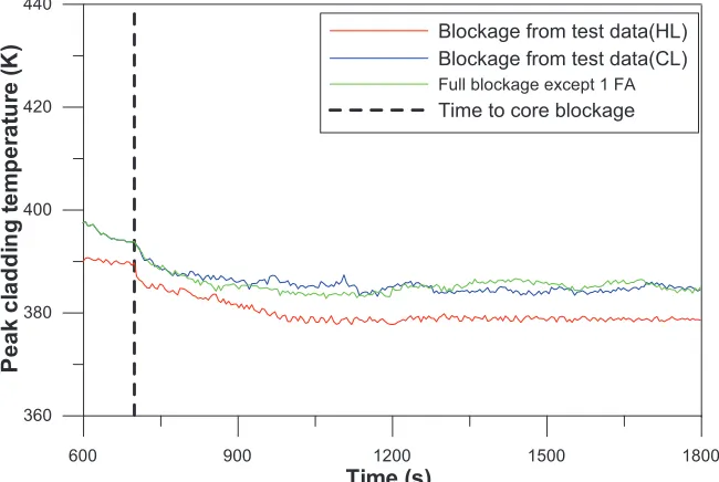
Figure 7 shows peak cladding temperature (PCT) of the hot channel of P140. There are no significant PCT excursions after the core blockage is simulated. The PCTs for both blockage models are maintained below the acceptance criteria of 700 K in the LTCC analysis. The figure shows the continuous LTCC capability of the APR1400 by the ECCS under the condition of the core inlet blockage and the chemical deposition on the fuel cladding.
600 900 1200 1500 1800
Time (s) 360 380 400 420 440 P e a k c la d d in g t e m p e ra tu re ( K
) Blockage from test data(HL)
Blockage from test data(CL) Full blockage except 1 FA Time to core blockage
Figure 7. Peak cladding temperature under the core blockage conditions.
23rd Conference on Structural Mechanics in Reactor Technology Manchester, United Kingdom - August 10-14, 2015 Division V
600 900 1200 1500 1800
Time (s)
0 1 2 3 4
C
o
ll
a
p
s
e
d
l
e
v
e
l
(m
)
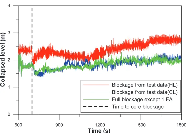
Blockage from test data(HL) Blockage from test data(CL) Full blockage except 1 FA Time to core blockage
Figure 8. Water level at the core.
CONCLUSIONS
RELAP5/MOD3.3 simulations were run assuming the core blockage obtained from the test data and full core blockage except one FA during the cold-leg break of double ended guillotine. The PCT of the hot rod shows that no late heat up occurs, the maximum local and core-wide oxidation calculation for traditional analysis are applicable. It is concluded that sufficient coolant can enter the core to remove decay heat with a maximum blockage of 99.6% at the core inlet, and the PCT is maintained below the acceptance criteria of 700 K.
REFERENCES
Andreychek, T.S., et al. (2011). “Evaluation of Long-term Cooling Considering Particulate, Fibrous and Chemical Debris in the Recirculating Fluid,” Westinghouse Electric Company LLC, WCAP-16793-NP Revision 2; accessible through U.S.NRC ADAMS, Accession No. ML11292A021.
Vaghetto, R., Hassan, Y. (2013). “Study of debris-generated core blockage scenarios during loss of coolant accidents using RELAP5-3D,”Nuclear Engineering and Design, UK, 261 144-155.
Suh, J.K., et al. (2015). “Experimental study of pressure drops through LOCA-generated debris deposited on a fuel assembly,”Nuclear Engineering and Design, UK, 289 49-59.