ISSN(Online): 2320-9801
ISSN (Print) : 2320-9798
I
nternational
J
ournal of
I
nnovative
R
esearch in
C
omputer
and
C
ommunication
E
ngineering
(An ISO 3297: 2007 Certified Organization)
Vol. 4, Issue 3, March 2016
Simulation and Closed Loop Control of
Multilevel DC-DC Converter for Variable Load
and Source Conditions
Heena I. Mansuri1, Dr.Yagnesh B. Shukla2, Madhusudan V. Gohil3
M.E Student, Dept. of E&C, SVIT, Vasad, Gujarat, India1
Professor & H.O.D, Dept. of E&C, SVIT, Vasad, Gujarat, India2
Assistant Professor, Dept. of EEE, VIER, Vadodara, Gujarat, India3
ABSTRACT: Power electronics converters are used in many field of electrical system. The converter has to face many
problems in power conversions and other reliability and stability limits. In DC to DC converter the main problem is voltage regulation. This project presents a novel non-isolated negative output DC-DC multilevel converter CUK. The proposed converter topology is suitable for photovoltaic applications where two voltages are needed at the same time with opposite polarity. The proposed DC-DC converter topology is the multilevel CUK converter. Negative output voltage is obtained from multilevel CUK converter. The gain of the converter can be increases by adding appropriate number of capacitors and diodes without disturbing the main circuit. The proposed converter will be implemented for DC load and PI controller is used to control the output voltage according to the requirement. The Proposed converter topology is simulated in MATLAB/SIMULINK environment.
KEYWORDS: Multilevel Cuk converter; Close loop control; Design of converter
I. INTRODUCTION
Power electronics is the application of solid-state electronics to the control and conversion of electric power. It also refers to a subject of research in electronic and electrical engineering which deals with the design, control, computation and integration of nonlinear, time-varying energy-processing electronic systems with fast dynamics.
The first high power electronic devices were mercury-arc valves. In modern systems the conversion is performed with semiconductor switching devices such as diodes, thyristors and transistors, pioneered by R. D. Middlebrook and others beginning in the 1950s. In contrast toelectronic systems concerned with transmission and processing of signals and data, in power electronics substantial amounts of electrical energy are processed. An AC/DC converter (rectifier) is the most typical power electronics device found in many consumer electronic devices, e.g. television sets, personal computers, battery chargers, etc. The power range is typically from tens of watts to several hundred watts. In industry a common application is the variable speed drive (VSD) that is used to control an induction motor. The power range of VSDs starts from a few hundred watts and end at tens of megawatts.
The power conversion systems can be classified according to the type of the input and output power
AC to DC (rectifier)
DC to AC (inverter)
DC to DC (DC-to-DC converter)
AC to AC (AC-to-AC converter)
DC to DC power converters like SMPS provides variable output voltage and current according to requirements. the main advantage of this converter is proper control. Control strategy of converter is very easy but voltage regulation of the system is very poor. Main problem of the system is variation in the voltage to lower to higher limit which can control by the control strategy. If proper control strategy is used to control the converter though voltage and current fluctuation affects load performance during lower to higher voltage regulation.
ISSN(Online): 2320-9801
ISSN (Print) : 2320-9798
I
nternational
J
ournal of
I
nnovative
R
esearch in
C
omputer
and
C
ommunication
E
ngineering
(An ISO 3297: 2007 Certified Organization)
Vol. 4, Issue 3, March 2016
Bandwidth of output is high.
Reduce the huge ratings of component as they are spited into small groups.
Minimum to maximum value difference increases which can provides better voltage regulation.
Output voltage and current ripples can bereduced.
A.Multilevel Topology
In this paper a novel non isolated dual output hybrid DC-DCmultilevel converter is proposed. The proposed converter topology provides a suitable solution to obtain two outputs with opposite polarity from a single DC source.
Fig.1 Multilevel converters[3]
The proposed DC-DC converter topology is the combination of two high gain multilevel DC-DC converters, one is multilevel boost converter and another is multilevel cuk converter. DC-DC Multilevel boost converter provides positive polarity output voltage and DC-DC multilevel cuk converter provides negative polarity
output voltage. Circuit diagrams of multilevel boost converter and multilevel cuk converter is shown in Fig1 (a)-(b). The main advantage of proposed topology is two output voltages are obtained by controlling single switch. Hence only one gate driver circuit is needed to drive the proposed converter. Voltage levels of both outputs can be increases by connecting more number of diode-capacitor stacks without modifying the main circuit. The voltage gain of proposed converter is depends upon the number of levels and duty cycle of switch.
B. Modes of operation
ISSN(Online): 2320-9801
ISSN (Print) : 2320-9798
I
nternational
J
ournal of
I
nnovative
R
esearch in
C
omputer
and
C
ommunication
E
ngineering
(An ISO 3297: 2007 Certified Organization)
Vol. 4, Issue 3, March 2016
forward biased, capacitors C1, C3, C5 and CC1, CC2, CC5 are charged by VIN, L1, C2, C4 and VIN, L1, CC2, CC4 respectively. When D7 and DC7 are forward biased, capacitors C1, C3, C5, C7 and CC1, CC3, CC5, CC7 are charged by VIN, L1, C2, C4, C6 and VIN, L1, CC2, CC4, CC6 respectively. When D9 and DC9 are forward biased, capacitors C1, C3, C5, C7, C9 and CC1, CC2, CC5, CC7, CC9 are charged by VIN, L1, C2, C4, C6, C8 and VIN, L1, CC2, CC4, CC6, CC8 respectively. At the same time inductor L2 is discharged. The operation modes and direction of current when switch S is not conducting.[3]
(a) (b) (c
ISSN(Online): 2320-9801
ISSN (Print) : 2320-9798
I
nternational
J
ournal of
I
nnovative
R
esearch in
C
omputer
and
C
ommunication
E
ngineering
(An ISO 3297: 2007 Certified Organization)
Vol. 4, Issue 3, March 2016
(g) (h) (i)
(j)
Fig.2 (a-c) Operation modes and direction of current when switch S is conducting. (d-e) Operation modes and direction of current when switch S is conducting. (f-j) Operation modes and direction of current when switch S is not
conducting[3]
II. SIMULATION OFCUKCONVERTER
ISSN(Online): 2320-9801
ISSN (Print) : 2320-9798
I
nternational
J
ournal of
I
nnovative
R
esearch in
C
omputer
and
C
ommunication
E
ngineering
(An ISO 3297: 2007 Certified Organization)
Vol. 4, Issue 3, March 2016
Continuous powergui Vs v + -Voltage Measurement1
v+
-Voltage Measurement Scope3 Scope2 Scope1 Pulse Generator1 Load L2 L1 g m C E IGBT/Diode m a k Diode i+
-C urrent Measurement2
i
+
-Current Measurement1
C 2 C1
Fig.3 Simulation of open loop CUK converter
Simulation circuit of CUK converter is shown in figure above. This simulation is prepared in MATLAB environment and results of the simulation is shown in this chapter. Values of the simulation are shown in the table below:
Table1. List of parameter
Simulation Results:
Fig.4Output current and output voltage of Fig.5 Input Current and Input Voltage of Cuk
0 0.1 0.2 0.3 0.4 0.5 0.6 0.7 0.8 0.9 1
0 5 10 Time C u rr e n t
0 0.1 0.2 0.3 0.4 0.5 0.6 0.7 0.8 0.9 1
0 10 20 30 40 Time V o lt a g e
0 0.1 0.2 0.3 0.4 0.5 0.6 0.7 0.8 0.9 1
5 10 15 Time C u rr e n t( A )
0 0.1 0.2 0.3 0.4 0.5 0.6 0.7 0.8 0.9 1
0 5 10 15 20 Time V o lt a g e (V )
Name of parameter Value Name of component Value
ISSN(Online): 2320-9801
ISSN (Print) : 2320-9798
I
nternational
J
ournal of
I
nnovative
R
esearch in
C
omputer
and
C
ommunication
E
ngineering
(An ISO 3297: 2007 Certified Organization)
Vol. 4, Issue 3, March 2016
Cuk converter converter
Fig.6 (a) Duty Cycle generation (b) Voltage across the switch and current through switch
III.CLOSEDLOOPMULTILEVELCUKCONVERTER
Fig.7 Simulation of closed loop multilevel CUKconverter 0.1 0.1001 0.1002 0.1003 0.1004 0.1005 0.1006 0.1007 0.1008 0.1009 0.101 -0.5 0 0.5 1 1.5 Time M a g n it u d e
0.1 0.1001 0.1002 0.1003 0.1004 0.1005 0.1006 0.1007 0.1008 0.1009 0.101 0 20 40 Time V o lt a g e (V ) C u rr e n t( A ) Continuous powergui Vs Vref1 250 Vref v + -Vout
ISSN(Online): 2320-9801
ISSN (Print) : 2320-9798
I
nternational
J
ournal of
I
nnovative
R
esearch in
C
omputer
and
C
ommunication
E
ngineering
(An ISO 3297: 2007 Certified Organization)
Vol. 4, Issue 3, March 2016
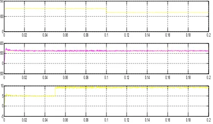
Simulation Results
IV.RESULTS ANALYSIS
From the results shown, the output voltage remains constant in every variable conditions. In the first condition the load condition is varied but the output voltage remains same. Same way in second results the variation of input voltage with respect to output is shown with variable load conditions. Our output voltage will remains consent as reference provided to it.
Multilevel topology for CUK converter is much more reliable system which is used in any variable DC voltage application. This converter provides fine voltage regulation to meet the voltage requirement and control the speed of DC motor. There are some more objectives which are listed as bellow:
• To achieve high voltage regulation.
• Decrease ratings of component
• Decrease the size of converter.
• Decrease number of component.
REFERENCES
[1] ManikantanE;.Jutty and Marian K. Kazimierczuk, Senior Member, IEEE,“ Efficiency of the Transformer Cuk PWM Converter”,IEEECH3306-8/93/0000-0639,1993.
[2] P.NagalakshmiKannaand Dr.B.Meenakshi” Analysis and Design of DC- DC/AC Non Isolated Cuk Converter using Sliding Mode Controller”,International Conference on Circuit, Power and Computing Technologies [ICCPCT],2015
[3] Mahajan SagarBhaskarRanjana, NandyalaSreeramulaReddy and RepalleKusalaPavan Kumar” Non-Isolated Dual Output Hybrid DC-DC Multilevel Converter for Photovoltaic Applications”, 2nd International Conference on Devices, Circuits and Systems (ICDCS),2014
[4] MiaosenShen, Fang ZhengPengand Leon M. Tolbert, IEE members,” Multilevel DC–DC Power Conversion System With Multiple DC Sources”, IEEE TRANSACTIONS ON POWER ELECTRONICS, VOL. 23, NO. 1, JANUARY 2008.
[5] R. Sriranjani, A. ShreeBharathi and S. Jayalalitha ,” Design of Cuk Converter Powered by PV Array , Research Journal of Applied Sciences,Engineering and Technology 6(5): 793-796, 2013
[6] M. H. Rashid, “Power Electronics: Circuits, Devices, and Applications”, Book, Prentice Hall Inc., 3ed Edition, 2011. [7] K. B. Khanchandani, “Power Electronics”, Book, TATA McGRAW HILL, 2nd Edition, 2011.
[8] Muhammad Ali Mazidi, “The 8051 microcontroller and Embedded System”, Book, PEARSON, 2nd Edition, 2006.
[9] EbrahimBabaei, Mehdi Mahaei, “Improving Output Voltage of the Three Phase Six-Switch Inverters” TELKOMNIKA, Vol.9, No.3, December 2011, pp. 497~502, ISSN: 1693-6930.
[10] S.UmamaheswariP.R.ThakuraR.K.Keshri, “Hardware Development of Voltage Source Inverter for Hybrid Electric Vehicle” 978-1-61284-379-7/11$26.00_c 2011 IEEE.
[11] Mohamed H. Saied, M. Z. Mostafa, T. M. Abdel-Moneim and H. A. Yousef, “new 13-space vector diagram for the threephase Six-switches voltage source inverter” international conference on communication, computer and power (icccp'09) muscat, february 15-18, 2009
[12] K. Rajasekara, “Power electronics for the future of automotive industry,” Proceedings of PCIMEur., Nuremberg, Germany, May 2002.
[13] Zhong Du et al, “DC–AC cascaded h-bridge multilevel boost inverter with no inductors for electric/hybrid electric vehicle a pplications”, IEEE Trans. on Industry Applications, vol. 45, no.3, May/June 2009.
[14] K. A. Corzine, F. A. Hardrick, and Y. L. Familiant, “A cascaded multilevel h-bridge inverter utilizing capacitor voltages sources,” in Proc. of IASTED Conference, Palm Springs, CA, 2003, pp. 290– 295.
0 0.01 0.02 0.03 0.04 0.05 0.06 0.07 0.08 0.09 0.1
96 98 100 102 V o lt a g e ( V in )
0 0.01 0.02 0.03 0.04 0.05 0.06 0.07 0.08 0.09 0.1
-200 0 200 400 V o lt a g e ( V )
0 0.01 0.02 0.03 0.04 0.05 0.06 0.07 0.08 0.09 0.1
-5 0 5 10 Time C u rr e n t (A ) Vref Vout
0 0.02 0.04 0.06 0.08 0.1 0.12 0.14 0.16 0.18 0.2
0 100 200
0 0.02 0.04 0.06 0.08 0.1 0.12 0.14 0.16 0.18 0.2
-200 0 200 400
0 0.02 0.04 0.06 0.08 0.1 0.12 0.14 0.16 0.18 0.2
-5 0 5 10
Time
Figure 9: Figure 1: (A) Input Voltage (B) Ref. voltage and load voltgae (C) Loacurrent in variable input and variable load condition