18th International Conference on Structural Mechanics in Reactor Technology (SMiRT 18) Beijing, China, August 7-12, 2005 SMiRT18-G05-5
FINITE ELEMENT SIMULATION OF CRACK GROWTH IN BLANKING
PROCESS USING FLOATING COLLAPSED ELEMENTS
Farid R, Biglari
Department of Mechanical Engineering
Amirkabir University of Technology,
Hafez Avenue, Tehran, Iran
E-mail: [email protected]
Mehrdad Ghatrenabi
Department of Mechanical Engineering
Amirkabir University of Technology,
Hafez Avenue, Tehran, Iran
E-mail: [email protected]
Kamran M. Nikbin
Imperial College London
South Kensington Campus,
London SW7 2AZ, United Kingdom
E-mail: [email protected]
Mohamad R, Razfar
Department of Mechanical Engineering
Amirkabir University of Technology,
Hafez Avenue, Tehran, Iran
E-mail: [email protected]
ABSTRACT
Numerical simulations of fine blanking process using various finite element methods are presented in this work. In this paper the crack propagation process is simulated using a combined collapsed mesh generation system. A block of collapsed elements is used around the crack tip to increase the density of elements and accuracy of calculation. Remeshing is executed during the analysis. The collapsed block is moved in each mesh generation step so that its location is always around the crack tip. The results of this method are compared with the results of other F.E. simulations which have already been published. The results of simulations are presented for both fine and conventional blanking processes.
Keywords: Collapsed elements, Ductile Fracture, Crack growth, Finite element, Blanking Process.
1. INTRODUCTION
The majority of today’s consumed metallic products are produced by the conventional blanking process. These metallic products are normally made of sheet metal. During blanking shearing occurs when a punching die penetrates through the sheet metal thickness. A ductile fracture is usually expected in the shearing region of the sheet metal blanking since a high degree of formability is required for most multistage forming and blanking processes. The quality of sheared edges can be improved by controlling the cutting process. For this reason, an understanding of the shearing process and relevant parameters can effectively reduce the manufacturing costs and increase the quality of the sheared products.
Blanking processes are mainly divided into two categories: conventional and fine blanking processes. Figure 1 shows a comparison of two typical engineering products which have been produced by the conventional (Figure 1a) and fine blanking processes (Figure 1b).
Figure 1: Sheared surface of conventional blanking [1].
Viewing Figure 1, it is evident that the fine blanking technology gives closer dimensional tolerances by achieving higher sheared surface quality compared to conventional blanking. The latter process may result in a rough surface over much of the sheared regions. The main technological differences between fine and conventional blanking can be summarized as follows:
1) Small clearance between die and punch
2) V-ring indentation that creates hydrostatic pressure and prevents premature fracture. 3) Application of counterforce punch that prevents ‘dishing’.
The existence of all the above mentioned features in the fine blanking process can create a narrow shear straining band in most cases, provided that compressive hydrostatic pressure is present. As a result, a straighter crack growth path is obtained. Furthermore the production of parts with close dimensional tolerances and higher sheared surface quality is possible.
In this paper the numerical studies of the simulations carried out for both fine and conventional blanking processes is presented and a ductile fracture oriented finite element procedure is used. The commercial finite element code ABAQUS [11] along with a user written program in Visual Fortran language has been employed to conduct the simulation of shearing process. The Visual Fortran program controls the boundary conditions in each ABAQUS run trial during the load/displacement increments based on a ductile shearing criterion. Comparison of the fine blanking and conventional blanking process can be made numerically using the ductile fracture criterion to explain the formation of the shear strain band and stress concentration in the cutting regions.
2. MATERIAL PROPERTIES
A conventional power law has been used to simulate mechanical behavior of the material as follows:
0 0
0
,
,
σ
σ
σ
σ
ε
σ
σ
ε
σ
>
≤
⎩
⎨
⎧
+
=
=
n
K
E
(1)
Table 1: Material parameters used in the simulations.
ν E
K (MPa)
n
value (GPa)
o σ
(MPa) 1048 0.196 0.29 585 250
3. DUCTILE FRACTURE CRITERIA
A ductile fracture criterion can be used to simulate a shearing process resulting from excessive plastic deformation. Two ductile fracture criteria have been used in this research work; plastic strain and Clift (or Freudenthal) criterion [12, 13]. These are listed in Table 2.
Table 2: Fracture criterion and constant values.
Fracture
criterion Function Constants
Freudenthal/Clift
∫
R eqd eq =C εε
σ
0 1 C1= 4260
Equivalent
plastic strain εeq=C2 C2= 4.2
Here εeq is equivalent (Von Mises) plastic strain, σeq is equivalent stress, C1 and C2 are material constants which are
determined from uniaxial and plane strain tensile tests.
There are various numerical methods to utilize plastic deformation limits in the fractured zone [14]. These can be classified as follows:
1- Element deleting 2- Element splitting 3- Node separation
4- Reducing element stiffness in fractured zone
In this paper the node separation method in conjunction with floating collapsed element method is used to simulate the fractured zone. When the strain and stress history in each element reaches a critical level as stated in Table 2, that corresponding node couples is released.
4. SIMULATION CONDITIONS AND TOOL DIMENSIONS
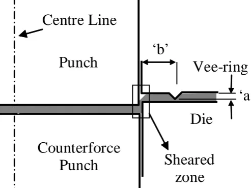
A circular disc with diameter of 18 mm and thickness of 1 mm has been used in all simulations as the blank. The dimensions and geometry of the V-ring and the punch/die tooling are shown in Figure 2 and Table 3.
Punch
Die
Vee-ring
Counterforce
Punch
‘b’
‘a’
Sheared
zone
Centre Line
Figure2: Geometrical illustration of fine blanking.
Table 3: Tooling geometrical and contact parameters.
Parameter Conventional
blanking
Fine blanking
Punch/Die Clearance 0.05 mm 0.005 mm
Height of the v-ring ‘a’ Not used 0.4 mm
Position of the v-ring ‘b’ Not used 1.2 mm
Punch diameter 18 mm
Punch corner radius 0.04 mm
Die corner radius 0.2 mm
Friction coefficient 0.1
It should be acknowledged that the simulation of conventional blanking has been carried out without the use of the V-ring and the counter punch shown for fine blanking in Figure 2.
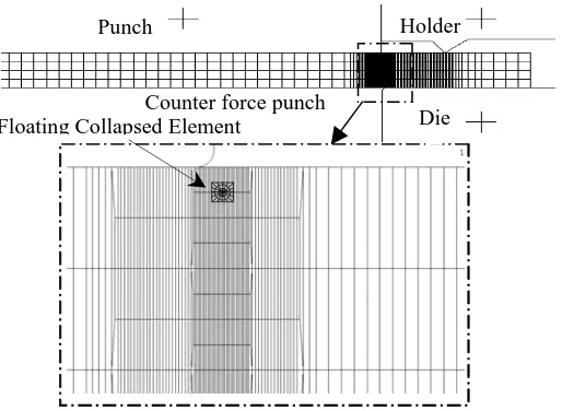
Sections of the finite element model of the sheet metal disc are illustrated in Figure 3. Half of the circular sheet metal disc has been modeled and eight-noded axisymmetric elements have been used. The blanking tools including the V-ring, punch and the die are assumed to be rigid and are indicated in Figure 3 by solid lines. The elements located near the punch/die clearance and V-ring indentation zone have been refined locally in order to increase the number of interpolation points that gives displacement solutions in the large plastic deformation regions.
Holder Punch
Floating Collapsed Element
Counter force punch
Die
Figure 3: Finite element model of blanking Process.
A total of 3100 elements and 7700 nodes used in the model have been illustrated in Figure 3. In this figure, the smallest element size is 0.0015 mm × 0.065 mm. Coulomb friction is assumed with a friction coefficient of 0.1 for the V-ring and the punch/die contact interactions with the sheet metal surface.
5. NUMERICAL PROCEDURE USED FOR SIMULATION
Start
Automatic Solution map of stress fields to new crack model Fortran Program
Node releasing check
Determining which nodes to be
released
Crack reached the
thickness?
Stop NO
YES Writing new input
file for ABAQUS
A
A
Reading the Stress and Strain
solutions
Automatic running ABAQUS
Figure 4: Flowchart of automatic crack propagation in sheet metal blanking process.
Viewing the flowchart of Figure 4 it is evident that the crack propagation simulation in sheet metal blanking process is carried out in several stages that are explained as follows:
1) The Visual Fortran program controls the Node release checks. This check will be performed for all loading steps from the beginning to the end of the blanking process.
2) Next an input file is created for the ABAQUS runs according to the node release checks. 3) Automatic map solution is done to transfer the stress and strain fields to new model. 4) Next, the ABAQUS analysis is carried out
5) In the next step, the output values such as nodal displacements, strain and stress fields in the highly deformed elements are extracted from ABAQUS
6) The fracture parameters are determined and critical levels of fracture criterion functions are calculated for the elements in the punch/die clearance region.
7) Nodes that are required to be released are identified. 8) New input file for ABAQUS run is generated.
9) Final checks are carried out in each flowchart cycle to determine the end of the crack propagation process.
It should be acknowledged that this analysis allows for multi-crack nucleation which is normally expected in those regions that undergo combined high tensile and shear loadings.
6. SIMULATION RESULTS:
Conventional Blanking
0 5000 10000 15000 20000 25000 30000 35000 40000
0 0.2 0.4 0.6 0.8 1 1.2
Punch Penetration(mm)
For
c
e
(N
)
plastic strain freudenthal without damage
plastic strain freudenthal without damage plastic strain with collapsed element
0
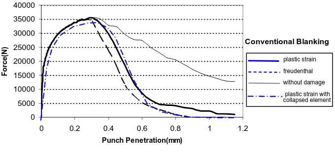
Figure 5: Load vs displacement of punch in conventional blanking process.
Figures 5 and 6 illustrate a sharp drop of load in different punch penetrations for two cases of the conventional and fine blanking processes. In these two figures, a comparison between the conventional and fine blanking processes is demonstrated. It can be seen that the punch force starts to drop at a punch penetration less than 0.3 mm in the fine blanking (Figure 6) whereas in the conventional blanking this drop starts close to 0.4 mm (Figure 5). The early sharp drop of force at lower punch penetration values for the fine blanking process indicates that the shearing process starts sooner and surface fracture initiates earlier than the conventional blanking process. It can also be seen that the use of remeshing technique can delay crack initiations. It seems that the reason for this phenomenon is likely related to less distortion of elements in the deformation area. Usually less distortion of elements can result in more accuracy of the calculations.
Fine Blanking
0 5000 10000 15000 20000 25000 30000 35000 40000
0 0.2 0.4 0.6 0.8 1
Punch Penettration(mm)
Fo
rc
e
(N
)
plastic strain freudenthal without damage
plastic strain
freudenthal
without damage
plastic strain with collapsed element
Figure 6: Load vs displacement of punch in fine blanking process.
In Figures 5 and 6, when no damage criterion is used no nodes will be released and as a result higher values of punch force are reported. In these figures, both the maximum effective plastic strain and Freudenthal (Clift) fracture criterions predict similar deformation behavior. However, the punch force starts to drop earlier when the Freudenthal fracture criterion is used.
Conventional Blanking 0 10 20 30 40 50 60 70 80 90 100
0 0.2 0.4 0.6 0.8 1 1.2
Punch Pene tration(mm)
A n g le o f P u n ch T ip R eact io n For c e (de gr e e ) θ plastic strain freudenthal without damage
Figure 7: Angle of punch tip reaction force in conventional blanking process.
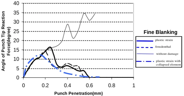
A gradual and increasing trend in the angle for all three fracture criteria is evident in Figure 7. This indicates that in conventional blanking the lateral force increases as the punch penetrates fully into the sheet metal. However, in Figure 8 beyond a punch penetration of 0.2 mm, the angle decreases, when either of the fracture criteria is employed. The force angle at the punch tip reduces to almost zero which indicates no lateral reaction force to the punch. Even for the case when damage is not included the angle of the reaction force is considerably lower for fine blanking. This result shows that the use of the V-ring in the fine blanking process reduces the lateral force generated by excessive plastic deformation between the punch/die clearance regions.
Fine Blanking 0 5 10 15 20 25 30 35 40
0 0.2 0.4 0.6 0.8 1
Punch Penetration(mm) A ngl e of P unc h Ti p R e a c ti on F o rce( d e g ree) plastic strain freudenthal without damage plastic strain freudenthal without damage
plastic strain with collapsed element
Figure 8: angle of punch tip reaction force in fine blanking process.
Figures 9 and 10 demonstrate the distribution of equivalent stress for the conventional and fine blanking processes in the sheared zone (as illustrated in Figure 2). Each set of figures consists of three fracture cases that are labeled as (a) without damage, (b) effective plastic strain criterion, (c) Freudenthal criterion and (d) effective plastic strain criterion using floating collapsed elements which are themselves divided into two figures showing 30% and 50% punch penetrations. In these figures, the green regions correspond to the regions of highest stress.
∆d=30% ∆d=50%
a
∆d=30% ∆d=50%
b
∆d=30% ∆d=50%
c
Figure 9: Equivalent effective stress; (a) Without damage, (b) Effective plastic strain, (c)
Freudenthal in conventional blanking process.
∆d=30% ∆d=50%
a
∆d=30% ∆d=50%
b
∆d=30% ∆d=50%
c
∆d=30% ∆d=50%
d
Figure 10: Equivalent effective stress; (a) Without damage, (b) Effective plastic strain, (c)
Freudenthal in fine blanking process, (d) Fine blanking with floating collapsed elements
The distribution of equivalent plastic strain for the conventional and fine blanking processes is illustrated in figures 11 and 12. Similar to the stress distribution contour plots presented earlier, four sets of plastic strain figures are given for four conditions that were listed earlier and here the light blue regions indicate the highest strained regions.
By comparing Figures 11b and 12b, it can be observed that the plastic strain in the shear band is more concentrated in the fine blanking simulations. A narrower straining band means a straighter crack path that can result in a better sheared surface quality.
∆d=30% ∆d=50%
a ∆d=30% b ∆d=50%
∆d=30% ∆d=50%
c
Figure 11: Equivalent effective plastic strain; (a) Without damage, (b) Effective plastic strain,
(c) Freudenthal in conventional blanking process.
crack crack
crack
∆d=30% ∆d=50% ∆d=30% ∆d=50% ∆d=30% ∆d=50% ∆d=30% ∆d=50%
a b c d
Figure 12: Equivalent effective plastic strain; (a) Without damage, (b) Effective plastic strain,
(c) Freudenthal in FINE blanking process, (d)Fine blanking with floating collapsed elements
7. CONCLUSION
A numerical simulation of ductile crack growth in blanking process has been accomplished in this paper. A ductile fracture mechanics procedure implemented within a finite element framework has been employed in order to obtain the fracture path during the shearing process The fracture path is found according to the movement of floating collapsed elements at the tip of the crack based on effective plastic strain histories which is used to calculate critical levels of fracture criterions. The ductile fracture criterions used in this work are the critical effective plastic strain and Clift (Freudenthal) criterions [10]. A greater amount of crack growth was obtained when the Clift model is used in both conventional and fine blanking simulations.
The strain distributions in both sets of simulations for the fine and conventional blanking process showed that more concentrated plastic strains occur in the shear band between the punch and die which can result in a sharper and straighter cutting path and an increase in the quality of the sheared surface.
REFERENCES
[1] Hambli, R., 2001, “Finite element simulation of fine blanking processes using a pressure-dependent damage model”, Journal of materials processing technology, 116, pp. 252-264.
[2] Lee T.C., Chan L.C., Wu B.J. 1995, “Straining behavior in blanking process-fine blanking vs. conventional blanking” J. materials processing technology, 48, pp. 105–111.
[3] Chan L.C., Lee T.C., Wu B.J. 1998, “Experimental study on the shearing behavior of fine–blanking versus bar cropping” J. materials processing technology, 80-81, pp. 126–130.
[4] Kondo K., Suzuki H., 1996, “Research on the accuracy of sheared products by different working principles
[5] Kwak T.S., Kim Y.J., Bae W.B., 2002, “Finite element analysis on the effect of die clearance on shear planes in fine blanking “J. materials processing technology, 130–131, pp. 462-468.
[6] Kwak T.S., Kim Y.J., Seo M.K.and Bae W.B., 2003," The effect of V-ring indenter on the sheared surface in the fine-blanking process of pawl", J. materials processing technology, 143–144, 20, pp. 656–661.
[7] Aoki I. and Takahashi T., 2003, “Material flow analysis on shearing process by Fourier phase correlation method – analysis of piercing and fine blanking”, J. materials processing technology, 134, pp. 45-52
[9] Chen Z.H., Chan L.C., Lee T.C. and Tang C.Y., 2003, “An investigation on the formation and propagation of shear band in fine blanking process”, Journal of materials processing technology, 138, pp. 610-614
[10] Biglari F. R., Tavakoli Kermani A., Habibi Parsa,M., Nikbin K. M. and O'Dowd N. P., " Comparison of Fine and Conventional Blanking Based on Ductile Fracture Criteria", Proceedings of ESDA 2004, 7th Biennial ASME Conference on Engineering Systems Design and Analysis, July 19-22, 2004, Manchester, UK
[11] Hibbitt, Karlsson & Sorensen Ltd., 2003. ABAQUS version 6.3.
[12] Hartley P, Pillinger I. and Sturgess C., 1992," Numerical modeling of material deformation process research", Development and Application, Berlin, Springer.
in precision shearing” J. materials processing technology, 56, pp. 70–77.
[13] Clift S.E., Hartley P., Sturgess C. and Rowe G., 1990," Fracture prediction in plastic deformation process”, International journal of mechanical sciences, 32, pp.1-17.
![Figure 1: Sheared surface of conventional blanking [1].](https://thumb-us.123doks.com/thumbv2/123dok_us/1460212.1178911/2.595.178.431.231.383/figure-sheared-surface-conventional-blanking.webp)