University of Windsor University of Windsor
Scholarship at UWindsor
Scholarship at UWindsor
Electronic Theses and Dissertations Theses, Dissertations, and Major Papers
1-1-1964
Heterogeneous reactions with rotating disk electrode.
Heterogeneous reactions with rotating disk electrode.
Hing Y. Lo
University of Windsor
Follow this and additional works at: https://scholar.uwindsor.ca/etd
Recommended Citation Recommended Citation
Lo, Hing Y., "Heterogeneous reactions with rotating disk electrode." (1964). Electronic Theses and Dissertations. 6357.
https://scholar.uwindsor.ca/etd/6357
HETEROGENEOUS REACTIONS WITH ROTATING DISK ELECTRODE
BY HING Y. LO
A Thesis
Submitted to th-:-. Faculty of Graduate Studies through the Department of Chemical Engineering in Partial
Fulfillment of the Requirements for the Degree of Master of Applied Science
at the University of Windsor
UMI Number: EC52537
INFORMATION TO USERS
The quality of this reproduction is dependent upon the quality of the copy
submitted. Broken or indistinct print, colored or poor quality illustrations and
photographs, print bleed-through, substandard margins, and improper
alignment can adversely affect reproduction.
In the unlikely event that the author did not send a complete manuscript
and there are missing pages, these will be noted. Also, if unauthorized
copyright material had to be removed, a note will indicate the deletion.
®
UMI
UMI Microform EC52537
Copyright 2008 by ProQuest LLC.
All rights reserved. This microform edition is protected against
unauthorized copying under Title 17, United States Code.
ProQuest LLC 789 E. Eisenhower Parkway
APPROVED BY:
ABSTRACT
The theory of convective diffusion to a rotating disk surface has been reviewed.
With the use of a rotating platinum plated cathode and
platinum anode, the theory has been verified for rotational speeds up
to 40,000 revolutions per minute.
The electrode process,
1“ + 2 e--- 31"
with potassium iodide as the supporting electrolyte, was chosen for
this study.
-4
Iodine concentrations ranged from 1.01 x 10 to 32.4 x -4
10 N in 0.1 N potassium iodide.
The reaction was also observed for several disk areas.
An average diffusion coefficient of the triiodide ions
was calculated from the data to be 1.01 x 10 cm. / sec. at
ACKNOWLEDGEMENT
The author wishes to express his deep gratitude to Dr. I. Koszman for his guidance^helpful criticism and suggestions.
He is indebted to Mr. W. Proby for the construction of part of the
apparatus.
This work was supported by the National Research Council
TABLE OF CONTENTS
ABSTRACT ii
ACKNOWLEDGEMENT iii
TABLE OF CONTENTS - iv
LIST OF FIGURES v
LIST OF TABLES vi
Chapter
I INTRODUCTION 1
II LITERATURE REVIEW 3
A. Theoretical B. Experimental
III THEORY 6
IV EXPERIMENTAL 13
A. Apparatus B . Solutions C . Procedure
V RESULTS 22
VI DISCUSSION AND CONCLUSION 30
BIBLIOGRAPHY 3k
NOMENCLATURE 36
APPENDIX A Velocity Distribution for a Rotating Disk 39
APPENDIX B Concentration Distribution for a Rotating Disk ¥
1-APPENDIX C Calculations of Diffusion Coefficient U8
APPENDIX D Calculations of Standard Deviation 51
APPENDIX E Tables 33
VITA AUCTORIS 60
Figure 1
Figure 2
Figure 5
Figure 4
Figure 5
Figure 6
Figure 7
Figure 8
Figure 9
Figure 10
Figure 11
Figure 12
Figure lj
LIST OF FIGURES Turbine
Turbine and Vessel
Layout of Equipment
Schematic Diagram
Current vs. Potential
Effect of the Concentration of KI on Limiting Current
Diffusion Current as a Function of S ( low concentration )
Diffusion Current as a Function of S ( high concentration )
Diffusion Current as a Function of Disk Area
Diffusion Current as a Function of Concentration of I„
Flow in the Neighbourhood of a Rotating Disk
Velocity Distribution for a Rotating Disk
LIST OF TABLES
Table Table Table
Table Table
Table 1
2
3 k
5
6
Table 7
Table 8
Table 9
Table 10
Data of Diffusion Coefficient Sample Calculation of Slope Tabulated Results of b
2
Calculations of ( b. - F )' x '
Current v s . Potential
Effect of Concentration of KI on Limiting Current
Diffusion Current as a Function of S ( low concentration )
Diffusion Current as a Function of S' ( high concentration )
Diffusion Current as a Function of S for two Disk Areas
Diffusion Current as a Function of^S for Concentration of Igg* 1.01x10* and Disk Area » 0.56 cm
CHAPTER I INTROUDCTION
The nature of the rate processes of most chemical and
physicochemical operations is largely determined by hydrodynamic
factors. Among such operations, heterogeneous transformantions in liquids and gases are of primary importance. The reaction rate of an
electrode process, which can be considered of as a special type of heterogeneous chemical reaction, is governed by three steps:
( L) transport of ions from the bulk of the solution to the surface of the electrode, (2 ) the electrochemical reaction itself and (3) the
removal of the final products.
In some cases, the heterogeneous reaction process is accompanied by secondary effects, such as the release of large
amounts of heat or the appearance of bubbles due to formation of
gaseous reaction products which complicate the course of the reactions.
The net rate of the heterogeneous process is determined by the
combined effect of its separate stages. However, the rate of the
entire process is governed by the slowest step if this step is
significantly slower than the others. This is common for reactions
occuring in successive stages. In those cases where the slow step
involves the introduction or removal of reactants, the reaction is said to be diffusion controlled and is governed by the laws of
diffusion kinetics. If on the other hand, the chemical or physical transformations constitute the slowest step, the rate of the reactions is determined by the kinetics of these processes.
2
Of greatest interest in current research, are those
reactions whose rates are determined by chemical reaction kinetics. However, the majority of heterogeneous reactions and especially hhose
of industrial importance are diffusion controlled. Most electro chemical reactions are of this type, i.e. controlled by the transfer
of ions to the surface of the electrode.
The passage of current through the solution leads to a change in concentration at one of the electrodes. This is called
concentration overpotential, which is also known as concentration
polarization in electrochemistry. In order to maintain a finite rate
for the overall electrochemical process, an external electromotive
force must be applied.
In electrolytic processes, ions are transported by three mechanisms under steady state and laminar flow conditions.
(1) Migration in the electric field applied to the cell. (2) Diffusion from region of higher concentration to
lower concentration.
(3) Convection due to motion of fluid.
In the absence of noticeable overvoltage, if the solution contains an excess amount of indifferent electrolyte, the magnitude of the current flowing to the electrode will depend on the
hydrodynamic factors which determine the effective thickness of the
CHAPTER II
A. Theoretical
Nernst (19) who was first to attempt to develop the
theory of the diffusion layer suggested that fa
“ D n F Co
-'diff " S'
where
1 = diffusion flux
•Miff
c0 = concentration of ions at the electrode
c^ a the bulk concentration
D * diffusion coefficient
n a ion valency
F a Faraday number
S ' a Nernst1s diffusion layer
Nernst postulated that the thickness of the diffusion layer is independent of the nature of the electrochemical process on the
electrode surface and independent of the character of the potential
distribution. The absolute value of £ ’ depends on the regime of
stirring and must be found experimentally.
This theory was found later to be inadequate, because it
contains the erroneous assumption that the liquid is stationary within the diffusion layer, and it also does not allow quantitative
prediction of the dependence of £* on the regime of stirring.
hydrodynamic theory of the transport of matter in a moving fluid.
However, he did not give a general theory of the transport of matter in a liquid.
In the theory of concentration polarization proposed by
V. Levich (15), (16) a quantitative theory of the diffusion boundary layer for electrodes of several shapes has been treated in terms of modern hydrodynamic concepts following the lines of analogous heat
transfer problems. For the case of a rotating disk, Levich found that the diffusion layer thickness is given by
s - / • « /
( - j - f i - l r f
(2
where
£ = diffusion boundary layer
D = diffusion coefficient
v = kinematic viscosity
CO = angular speed
The hydrodynamic equations for a rotating disk were first solved by an approximate method given by Karman (13). Later
Cochran (3) calculated more accurate values by a method of numerical integrations.
A more thorough discussion of a rotating disk electrode was given by Levich (17) in his theoretical studies of diffusion and kinetics.
B. Experimental
disk apparatus for other studies.
Kabanov and Siever (12) first verified the equation of
ion transfer in their studies of the diffusional flow of dissolved
oxygen to a rotating disk and the limiting current for hydrogen ion reduction. The results of their observations confirmed the correctness
of the theory. Hogge and Kraichman (9) have applied the theory of
concentration polarization for a rotating disk electrode to the KI-KI_ system with a platinum electrode. Their speed of rotation
5
extended to about 5000 revolutions per minute. A diffusion coefficient for triiodide ions was obtained from their results.
Excellent agreement of experimental results with the
theory was also found by Aykazyan and Fedorova (1) in the study of
anodic ionization of hydrogen atoms in different electrolytes.
Other experimental studies using the rotating disk have
been done by Beacom and Hollyer Jr. (2); and also Johnson and Turner
(11) on the studies of addition agents; Jahn and Vielstick (10) and
Galus and Adams (8 ) on the measurement of kinetics of several
reactions; and Lewis and Ruetschi (18) on oxidation of hydrogen and
CHAPTER III
THEORY
In an electrolytic solution, the equation for the
transfer of ions due to diffusion and migratipn-takes the form
1
F+ -
2
z£?c
(
3)
r ' a y R T ' a y
where
iy. = limiting current density hy ion type Y T>y = diffusion coefficient
F » Faraday number
* <j> = potential
cy. * concentration of ions of type /"
c ° = initial concentration
T = absolute temperature
R = gas constant
y a normal distance from reacting surface
with the conditions for electroneutrality in solution
s . C r n r * o (k )
In . the case of the system KI-KI^ , with KI as the
supporting electrolyte, the concentration of the reacting ion species,
I”, is small in comparison with the other types of ions. Equations(3) and (If), then become
7
0
=-0
-n p d^2
Dip*^ ^ 4
n c & L + & £ l c £ & * a y r t 3 ^ 4
& )
( 7 )
yi'C/ + ti
2
cz +
??3
C
3
(V)
where suberipe 1 , 2 and 3 refer to ions of type 1^ , K and I* respectively. Equations (6) and (7) give
C z « Cz &
o TD C3 = C3 *
( 9 >
(JO)
where
«Q = F<t> & T
From i * id iff + ^ i g r * e1uations (5)» ($)> (9) and (10), results were obtained for the currents due to diffusion and migration.
= -I
* / / *
0
+
L VCm if, ~ i
CJ
i v * *
« < C
r *
00
az)
f * l « ( i + 1 K ~ )
2 V S F '
Therefore, the migration current can he neglected when compared to the diffusion current and it can he assumed that the flow
of current-carrying ions in the solution, in the presence of foreign
electrolyte, is equal to the diffusion flux of uncharged particles.
simplest form when the surface of a rotating disk serves as the
reaction site. The rotating disk is employed in electrochemistry and
is convenient for studying chemical kinetics under laboratory condi
tions. The velocity distribution for a rotating disk is of special interest in hydrodynamics because it is one of the few examples where
an exact solution of the hydrodynamic equations can be obtained. This
exact solution gives the velocity distribution throughout the body of the viscous fluid. Far from the rotating disk, the fluid moves
toward the disk, and in a thin layer immediately adjacent to its surface, the liquid acquires a rotating motion. The angular velocity
of the fluid increases as the rotating disk is finally attained. Furthermore, the fluid also acquires a radial velocity under the
influence of the centrifugal force.
at a rotating disk is that its thickness is not a function of the distance from the axis of rotation, but is constant over the entire
disk surface.
(J 4 )
To determine the convective diffusion equation has to be
solved.
The equations for convective diffusion acquire their
9
It is possible to show by doing a material balance for
the flux of ions in a control volume under steady state conditions that
= °
05)
where
J = D
VC
+ \fc
(15*0.)
For one dimensional flow, equation (15) gives the convective diffusion equation;
with boundary conditions
where
b
c = c at y = 00
c = 0 at y = 0
v = velocity in normal direction to the disk y
c = concentration
c*5 = bulk concentration
y = normal distance to disk
D = diffusion coefficient
j =s flux of ions
transport in the moving liquid, and the first term ordinary diffusion.
For the case of one dimensional flow, the ratio of these two terms in
order of magnitude equals to
where Pe is the dimensionless Peklet number. It is analoguous to the
Reynolds number for the flow of a liquid. In this sense, the regime
of transport of matter is determined by the value of the Peklet number. The ratio of the Peklet to Reynolds numbers is the dimensionless Schmidt number
In liquids, the Schmidt number is always very much larger than unity.
Because of this fact, the Peklet number is large compared with unity,
even when the corresponding Reynolds number is small. Therefore, in
most cases molecular diffusion in the bulk of the liquid can be
neglected in comparision with the convective transport of matter. Thus
if the peklet number is large compared with unity, the term due to
molecular diffusion in equation (15«0 may be dropped and the solution of equation (15) will be c - constant = c °, The concentration of matter
will thus be constant throughout the volume of the liquid. However,
this solution of the equation cannot be valid at the electrode surface S. where the condition c « 0 must be satisfied. There should, therefore,
be a thin layer of liquid near the surface of the electrode in which
07
)
Sc,
Pe
os)
11
the concentration varies rapidly. Thus, at large Peklet numbers, as well as at large Reynolds numbers, the entire liquid can be divided
into two parts; a region of constant concentration far from the
surface of the reaction and a region of rapid variation of concentrat
ion in the immediate vicinity of this surface. In the latter region, the derivatives of the concentration with respect to the co-ordinates are very large and as a result, the first term of equation (15a),
expressing molecular diffusion, becomes comparable to the second term, despite the small value of the diffusion coefficient and thus it cannot
be neglected. The layer is called the duffusion boundary layer which
is analogous to the Prandtl boundary layer.
conditions shows that c(t) ■» 0. Substitution of c(t) in equation (19) gives
where v , the normal velocity distribution, was obtained by solving the Navier Stokes equations of motion. The values are
c
K' [ s x p ( ' o ) • ¥ » + ) * +
'where K, and c(t) are integration constants. Application of boundary
v /
at
at y =
12
and
J.
where ^ is the hydrodynamic boundary layer thickness. Thus equation (19) can be integrated to give the limiting diffusion current density.
«? J .
= o . 4 z » C F » c o * ( * 2 ) (/*>
and the diffusion boundary layer thickness
Limiting diffusion current for a rotating disk with area A is obtained by rearranging equation (22)
J.
CHAPTER VI
EXPERIMENTAL
A. Apparatus
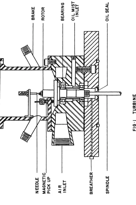
(a) Turbine:
Because of the particular requirements of this experiment
a high speed vertical turbine, purchased from Barbour Stockwell Company
was used. The turbine was of the air driven type having a maximum safe
operating speed of 150,000 revolutions per minute. The rotor of this
turbine was one and one half inches in diameter and designed for a 5/16 inch spindle. The spindle was suspended by means of a special
self locking hexagonal nut on top of the rotor as shown in Fig. 1.
Ball bearings in the housing were lubricated with a continuous stream of oil mist generated by an Alamite oil mist lubricator. The purpose
of the oil seal was to stop excess oil from leaking into the test
fluid below. Excess oil collected in the turbine would flow out
through an opening called the Breather which also maintained pressure
equilibrium between the lower part of the turbine housing and the
atmosphere.
The bottom part of the turbine was made of plexiglass to
prevent unnecessary electrical contact between the metal of the turbine
and the test fluid.
The vessel containing the test fluid was made air tight and concentric with the turbine by means of an 0-ring inserted into a
grove at the bottom face of the plexiglass.
of emergency.
(b) Vessel:
The vessel consisted of two parts as shown in Fig. 2.
The lower part was cut from five inches diameter plexiglass tubing to a length of four inches. This tube was gluedto a plexiglass plate which acted as the bottom of the vessel. Near this plate, two openings
were drilled in the wall, of the plexiglass tube for filling and
draining:purposes. The upper part of the vessel machined from
plexiglass block was six inches in diameter and one inch thick with a
groove and an O-ring to accept the bottom half of the vessel. This
part was so designed to keep the spindle from dragging air into the
test fluid and forming a vortex. The opening at the side of the top
part was for exhausting gases oT liquid and the opening at the center was for the entrance of the spindle.
(c) Electrodes
Cathode - The spindles which were to serve as the cathodes were machined to give the desired surface area and shape. They were
made of oil hardened, non-deforming type drill rod: which was free
from Decarb and annealed to give a fully spheriodized structure. No
heat treatment was involved. Bright platinum was plated uniformly on
the spindle only at the reaction surface by Johnson Matthey and Company Limited Toronto. The rest of the spindle, extending outside
the turbine was insulated with an electrical insulator, Dow Corning
Varnish 980. The spindle was dipped in the insulating varnish and dried for four hours and then oven-dried at 150*C for six hours. The
spindle was preheated to 150*C to drive out moisture before being
Anode - The anode was a thin pure platinum plate 3 . 1 2
inches in diameter and 0.015 inches thick, located at the center of the vessel approximately 5.5 inches below the cathode surface.
(d) Speed control:
The speed of the turbine was controlled by regulating
the air supply to the turbine by means of a pressure regulator and
valves placed in series. The high pressure air from the main
compressor first passed through a valve, then through ah air filter. A fixed value of pressure was established by a pressure regulator. The
desired pressure was determined by another valve just ahead of the turbine as shown in Fig. If-.
(e) Measuring apparatus:
The rotation of the turbine rotor was picked up by means
of a magnetic device located inside the top part of the turbine which
produced an alternating current with the frequency corresponding to
the speed of rotation. This alternating current was amplified and fed
into a digital electronic counter. For recording purposes, these digital numbers were converted in an analogue direct current signal
which could be recorded by an x-y plot recorder reading in millivolts. The diffusion current was measured with a milliammeter. For recording
purposes, this current was also converted into millivolts and recorded
by the x-y plot recorder. The voltage was measured with a precision voltmeter.
(f) Electrical contacts:
A small hole was drilled at the top end of the spindle. Electrical contact was made by means of a small needle pressed into
16
the magnetic pick up.
The platinum plate anode was screwed into the bottom of
the vessel with a metal screw which had been platinum plated. The other end of the screw extended out of the vessel so that electrical
contact could be made. A small O-ring was placed between the platinum
plate and the inside bottom face of the vessel to prevent leakage of
fluid.
B. Solutions
Reagent grade potassium iodide solutions were used. A
0.1 N stock solution was prepared and deoxygenated by flushing with
nitrogen which was first equilibrated with 0,1 N potassium iodide
prior to introduction: into the stock solution. The KI, complex was 5
obtained by dissolving reagent grade iodine in a concentrated KI
solution and diluting to produce the resulting solution which was 0.1N KI and 0.101 Nig. The distilled water used in preparing the
complex was also flushed with tank nitrogen.
The solutions for testing the effect of the supporting
electrolyte on limiting current were prepared in a similiar manner.
The concentration of prepared iodine solution was
determined by titration with arsenious oxide according to Kolthoff
and Sandell (lh).
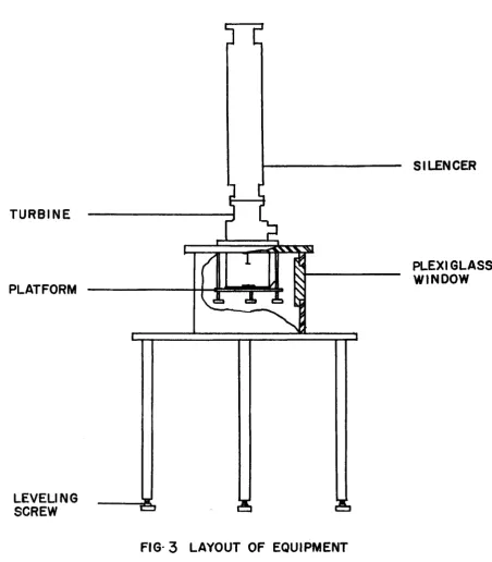
C . Procedure
before introduction into the reaction vessel through one of the lower openings. Leveling was done on the turbine surface by turning three screws underneath the legs of the table as shown in Fig. 5 . The oil
mist lubricator was turned on a few minutes before starting the turbine.
The setting of the needle valve and pressure of the lubricator was so adjusted that there was always a small amount of oil leaking through
the Breather. The air pressure was set at ^0 psig by adjusting the
regulator while the air pressure up stream was "JO psig. The speed of the turbine then was increased slowly by turning the vilive downstream of the regulator.
Direct current was supplied from a dry cell battery. The
voltage across e tetrodes was maintained at 0.4 volts during the
experiments by aajusting the rheostat to compensate for the ohmic drop
in the solution. Limiting current vhlues were then read for correspond
ing cathode speeds.
For the determination of potential-current curves at constant speeds, current were recorded for corresponding potentials
which were varied by resetting the rheostat.
m
firs#
m
FI
G
•
I
TU
RBI
NE
o
_J
z
UJ
UJ
nr
V
)
o
u>
<n
o
I
UJ
z
O
>
<
UJ O
o
X
ii
o
F
IG
*2
T
U
R
B
IN
E
8
V
E
S
S
E
SILENCER
TURBINE
PLEXIGLASS
WINDOW
PLATFORM
LEVELING
SCREW
CHAPTER V
RESULTS
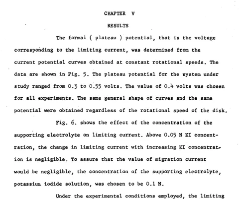
The formal ( plateau ) potential, that is the voltage
corresponding to the limiting current, was determined from the
current potential curves obtained at constant rotational speeds. The data are shown in Fig. 5. The plateau potential for the system under
study ranged from 0.5 to 0.55 volts. The value of O.h volts was chosen for all experiments. The same general shape of curves and the same
potential were obtained regardless of the rotational speed of the disk.
Fig. 6 . shows the effect of the concentration of the
supporting electrolyte on limiting current. Above 0.05 N KI concent
ration, the change in limiting current with increasing KI
concentrat*-ion is negligible. To assure that the value of migratconcentrat*-ion current
would be negligible, the concentration of the supporting electrolyte,
potassium iodide solution, was chosen to be 0.1 N.
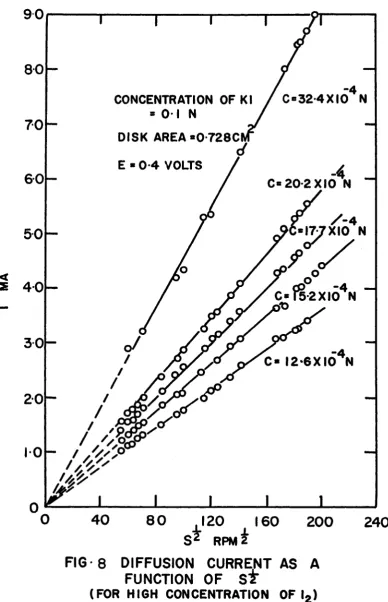
Under the experimental conditions employed, the limiting
diffusion currents were plotted against the square root of rotating
speed for various concentrations of iodine, as shown in Fig. 7 an<^ 8 * Straight lines were drawn through the experimental points and
extropolation of these lines back to zero rotating speed passed through the origin within the experimental errors.
Plots of the experimentally determined limiting diffusion
currents against concentrations of iodine and disk area indicated the
23
by similiar extrapolation.
Temperatures were measured before and after each
experiment. An average temperature of 2k.6 1 0 . 5 C was obtained.
2 The areas of the disks were measured as 0.728 + 0.01 cm f
2 2
0.^79 + 0.01 cm and 0.570 + 0.01 cm for the three disks.
Values of the kinematic viscosity of the test fluids
were taken from Hogge and Kraichman (9). v = 0.8679 centistoke at
80
7 0
CONCENTRATION OF l2 = 12-6 X 10 N
CONCENTRATION OF KI = 0 1 N
DISK AREA * 0-728 CM2
6 0
5 0
< 4 0
2
27,500 RPM
3 0
o—
25,500 RPM
20,5
00 RPM
■o—o— o o .
n.
20
12,5 00 RPM
2,500 RPM
0
0*2
0-4
0-6
0 8
1 0E VOLTS
R e p ro d u ce d w ith p e rm is sio n of the co p yr ig h t o w n e r. F u rth e r re p ro d u ct io n p ro h ib ite d w ith o u t p e rm is s io n .
1-50
CONCENTRATIONS OF l
2 * 5 05X1
DISK AREA « 0 728 CM2
E * 0 4 VOLTS
I 25
00005N KI
I
0 0
-0-050 N KI
0-075 N KI
0-75
<
z
050
-0-25
---20
0
40
60
80
100
120140
160
180
200
220
R e p ro d u ce d w ith p e rm is sio n of the co p yr ig h t o w n e r. F u rth e r re p ro d u ct io n p ro h ib ite d w ith o u t p e rm is s io n .
<
Z
2-8
2-4
'
-4
C» IO IXIO N
CONCENTRATION OF KI * 01 N
DISK AREA*0-728CM2
E * 0-4 VOLTS
20
C* 7
56X10 N
1-6
C« 5 05XI0"4N
0-8
-C *2 52XI04N
0-4
»-D--- 1
C-101X10N
0-0
0
20
40
60
80
100
i
ST
rpm
90
8 0
C«32-4XI04 N
CONCENTRATION OF KI
7 0
DISK AREA *0-728C
E « 0-4 VOLTS
6 0
C= 20-2X10 N
/-4
XIO N
5 0
as 4 0
C«f§-2XI04N
3 0
C* I2-6X|64N
2 0
“1 0
-0
4 0
8 0
1 2 0160
200
240
RPM 2
FIG - 8 DIFFUSION CURRENT AS A
FUNCTION OF ST
R e p ro d u ce d w ith p e rm is sio n of the co p yr ig h t o w n e r. F u rth e r re p ro d u ct io n p ro h ib ite d w ith o u t p e rm is s io n .
10
-CONCENTRATION OF KI *0 -IN
S = 36,500 RPM
E » 0*4
VOLTS
8
-6
--4
C* 24 6 X 10 N I
<
2
0-4
0 6
0-7
0 0 1
0-2
0-3
0-8
0-9
1 0R e p ro d u ce d w ith p e rm is sio n of the co p yr ig h t o w n e r. F u rth e r re p ro d u ct io n p ro h ib ite d w ith o u t p e rm is s io n .
CONCENTRATION OF KI *01
DISK AREA «0 728 CM2
E *0-4 VOLTS
= 190
» 141
6
-0 1 0
20
3 0
4 0
CHAPTER VI
DISCISSION AND CONCLUSION
3 5
Values of Reynolds numbers from JxlQ to 1x10 were
calculated from the equation
Re =
j m L
where
Re = Reynolds number
<*> = angular speed
r = radius of disk
v = kinematic viscosity
for maximum and minimum rotating speeds. This indicates that the flow
of fluid was within the laminar region. The radii of the disks were
large compared to the boundary layer thickness so that the edge effect
could be neglected.
The experimental results showed that for the system KI - KI^, under the above mentioned conditions, the mathematical
prediction proposed by Levich, equation (23), is valid.
The values of diffusion coefficient of triiodide ion have been determined by electrolytic and non-electrolytic methods.
51
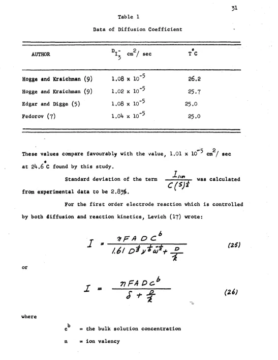
Table 1
Data of Diffusion Coefficient
AUTHOR D - I, cm / sec2,
5
0 T C
Hogge and Kraichman (9 ) 1.08 x 0
1 \S\
26.2
Hogge and Kraichman (9 ) 1.02 x io-5 25.7
Edgar and Digge (5) 1.08 x IQ'5 25.0
Fedorov (7) 1.0k X 10"5 25.0
2 These values compare favourably with the value, 1.01 x 10 cm / sec
«
at 2k. 6 C found by this study.
Standard deviation of the term — , was calculated
C(S)i
from experimental data to be 2 .83$.For the first order electrode reaction which is controlled by both diffusion and reaction kinetics, Levich (17) wrote:
r U F A D C 6
9 U ! * (Z5)
1k
orr
7 ) F A D C . b
S + f
(ziI
where
c^ - the bulk solution concentration
32
A s' disk area
D s diffusion coefficient
k sx kinetic ' rate constant
F = Faraday number
U) = angular speed
V = kinematic viscosity
s = diffusion boundary layer
For a diffusion controlled reaction is small compared to the
diffusion boundary layer thickness £ , equation (2). Equation (25) becomes equation (25).
I * 0.62 n P A D^ 3 v'1^ cb « 1^2 (25)
On the other hand if § can be decreased by increasing the speed of rotation without getting into hydrodynamic turbulence, equation (26)
becomes
I = n F A K cb (27)
It is clear that the observed limiting current becomes
independent of the diffusion rate > the current is entirely controlled by the reaction rate. The linear relationship between the limiting
current and the square root of the speed is no lbnger followed. The
limiting current is a constant and depends only on the concentration of the reacting ions.
Calculation of the diffusion boundary layer thickness according to equation (2) yields a value of 2.5 x 10 ^ cm for a
become constant for the electrode reaction under study.
This means that the rate constant for this process must
-2
have a value much larger that hxlO cm/sec if the thickness of the
diffusion boundary layer is to be negligible at the rotational speed
of h O , 000 revolutions per minute.
Difficulties arose when rotational speed were increased beyond h0,000 revolutions per minute. Vortex problem became appreciable.
Also, electrical contacts, speed control and insulation were difficult to maintain at high speeds.
It is recommended that a slower electrode reaction
could be studied with the present equipment for elucidation of
diffusion and reaction kinetics. Diffusion coefficients of ions can
be determined fairly easily and accurately with the preasently
BIBLIOGRAPHY
1. Aykazyan, E. A. and A.I. Fedorova, Doklady Adad. Nauk SSSR 86.
1137 (1952)
2. Beacom, S.E. and R.N. Hollyer Jr., J. Electrochem. Soc., 109 No. 6, k97 (1962)
3 . Cochran, W., The Flow Due To A Rotating Disk. Proc. Cambridge Phil.
soc. 30, 365 (193*0
h. Deming, W. E., Statistical Adjustment Of Data , John Wiley and
Sons, Inc., London (19*+3)
5 . Edgar, G. and S. H. Diggs, Amer. Chem. Soc. , 253 (1916)
6 . Euchen, Z., Elektrochem. , 38, 3^1 (1932)
7 . Fedorova, A. I., G. L. Vidovich, L. I. Boguslavsky and
V. D. Yukhtanova, Trudy Chtvertogo Soveshchania Po Electrokhimii,
665-668, Moscow. (1959)
8 . Galus, Z. and R. Adams, J. Phys. Chem. 67, 866 (19&3)
9 . Hogge, E. and M.B. Kraichman, J. Amer. Chem. Soc., 76, 1^31 (195*0
10. Jahn, D . n a d Vieldtick, J. Electrochem. Soc. 109 No. 6 , ^97 (1962) 11. Johnson, G. and D. Turner, J Electrochem. Soc., 109, No. 10,
918 (1962)
12. Kabanov, N. and Y. G. Silver, Zhur. Fiz. Khim. 22, 53 (19**8) 13. Karman, T. Lamlnare and Tubulente Reibung ZAMM I ., 233-252 (l92l);
NACA, T. M. 1692 (I9U6 )
I h . Kolthoff, I. and E. Sandell, Testbook of Quantitatine Inorganic
16 . Levich, V. Discussions Faraday Soc., 1_, 37 (19^7)
17. Levich, V. Physicochemical Hydrodynamics Prentice Hall Inc.
N. J. (1962)
18. Lewis, G. and P. Ruetschi, J Phys. Chem. 67, 65 (1963)
19. Nernst, Z. Physik. Chem., k’J, (190*0
20. Schlichting H. Boundary Layer Theory McGraw Hill Book Co. Inc New York (i960)
21. Sparrow and Gregg, J. of Heat Transfer ASME 2^9C, (1959)
22. Tobias, C.W., M. Eisenberg and C.R. Wilke, J. Electrochem. Soc.
NOMENCLATURE
2
A = disk area, cm
A = constant, eq. (A-I3), (A-Ut-) and (A-15)
a » constant, eq. (A-l6), (A-I7) and (A-18)
B ■ constant, eq. (A-I3), (A-lif) and (A-15)
b as constant, eq. (A-l6), (A-I7) and (A-18)
b = —h ™ ■
JS-C
b = mean value of b
b = intercept
C, Cg, and Cy
= concentrations, mol/ cm^
C , Cg, C5 and Cy
= initial concentrations, mol/ cm^
jj 7
C = bulk concentration, mol/ cm ^
C# = concentration at the electrode mol/ cm^
C (t) = integration constant, eq. (19)
D , D x, Dg, D5 and D^,
2
=s diffisopm cpefficient, cm / sec
d = diameter, cm
e =s electronic charge
E =a voltage, volts
F =a Faraday number
_ ’ . " = unknown functions, eq. (A-7)
F, F and F , ^
1 11
G, G and G » • unknown functions, eq. (A-8)
f «
H, H and H as unknown functions, eq. (A-9)
i = diffusion current, amperes
diff '
i ** migration current, amperes
migr ° ’
i . J, . = limiting mass flux, mol / sec
lim * lim ° *
J p Jg = integrals
k * kinetic rate constant, cm / sec
= integration constant, eq. (19)
N = normality
n s ion valency
, 2
p s pressure, gm / cm
f
P, P = unknown functions
Pe = Peklet number, eq. (17), dimensionless
r a radius, cm
Re = Reynolds number, dimensionless
R « gas constant
S = rotating speed, rpm
s = rotating speed, rps
Sc = Schmidt number, dimensionless
Si D. = standard deviation
t = norma}, distance, cm
T = absolute temperature, ° K
u = a function dependence
U = constant, eq. (A-12)
vr = radial velocity, cm / sec
v = tangential velocity, cm / sec
y = normal distance, cm
Y = defined function
= constant, eq. (A-ll)
&
a
angleus = angular speed, radian / sec
c = potential, volts
F4>
Ip = dimensionless function » ----—
* r = density, gm / cm
c>0 a Prantl boundary layer, cm
= diffusion boundary layer, cm O I
d = Nernst diffusion boundary layer, cm
fJi a absolute viscosity
2
>' = kinematic viscosity, cm / sec
a p p e n d i x a
THE SOLUTIONS OF THE NAVIER STOKES EQUATIONS OF MOTION
BY EXACT METHOD FOR ROTATING DISK
The disk is assumed to be sufficiently large, so that
the edge effects can be neglected, Also taking into account rotational
symmetry, Fig. 11, one can simplify the Navier Stokes equations and the continuity equation to
Ve z M l i i a , J4 ) ( * * )
!/
j.
+ 1 /^ 2 . —y (
f.
+ -L
)
(A~Z)
U = - - L £ £ (A-2)
P
[*H 2 **>* * 3 * '
J
-i)!k + QJfa.
j- -lL- +.
- o
(A^
a)
* 96
^ n,
s>y
CA *}
with boundary conditions
v = 0 v = r v = 0 at y = 0
* y (A-5)
V = 0 V« = 0 V = -V y = ®o
r & y J
Assume that the solutions to the equation of continuity which satisfy
the boundary conditions take the form.
vr = r<*F (| ), = xco G ( £ ), vy = }
P = - p y * i P(£ ) (A-6)
and the independent variable £ is given by
to Substitute equation (A-6) into equations (A-l) (A-2) (A-5) and'(A-lf)
to obtain the following equations
2 2 1
F - G + F H
V
= F
(
a
-
t
)
2
F G + & -a"
(A-8)\ ■ «t
H H = P + H (A-
9
)2
F + H* = 0 (A-10
)where F, G, H and P are functions to be determined, the boundary
conditions become '
F ■
0
G =1
H =0
11 0F -*•
0
G -*■0
H = p< at / = 00 (A-ll)where
u
_
(ycJ)t
(A-12
)only on the variable $ , the assumption made is justified. The
functions F G and H may be made to satisfy the above equations and
boundary conditions by formal series expansions. For large values
of f :
F = t e S
- £ £
i ^ t
e'*s
, . . . .
(A-»)
6
and for small values of
£ ,
F
= .a / -
S i . . L b f +.■■■
lA -n l
6
- ) + b $ +4
- * $ + .... ( A - n )H
=-*S +-f? +■■■■
iA'lS)
The constants A, B, a, b, and can be determined b y numberical
integration. Their values are :
a = 0.51023 b = -0.616 oA = 0 . 8 8 ^ 7
A = O.93U B = 1.208
The functions F, G and H are shown in Fig.
12
and the values of thevelocity in the direction normal to the disk are
, f i - O . ~ ( A - * * )
.
l/y X -0.51 ( - y f f
<1
(-&f
and it follows that
FIG*11 FLOW IN THE NEIGHBOURHOOD OF A
00
CMo
O CO
O
lO ro
Q
ro
to
CM
H<m
ii v r ^
in
m o
F
IG
-1
2
V
E
L
O
C
IT
Y
D
IS
T
R
IB
U
T
IO
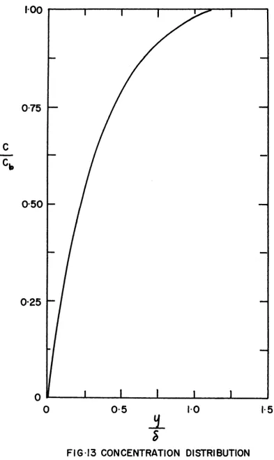
APPENDIX B
CONCENTRATION DISTRIBUTION FOR A ROTATING DISK
From equation (19)
C * K,
J
Sip (
£
Vib ) d y ) d t
O D
For purposes of evaluation the range of the integral is subdivided
into two regions: from zero to jf and from
£ 0
to infinityeo ^
7=
J &sLf> (~pja
t o "L "L
= /<e^
(-pUy(y)dy)Jt + L e*?‘
(-L !
0 Jc J o
9
J o=
7 > 7,
( * ' 0
Using the values from equations (A-19) and (A-20), ohe can.evaluate
the integrals and Jg
J > m j
(' “n 't\i
1*
<e -‘>
J.
________________CO
a
=
2 t . Letting
4 4 J -it -L
(£-3)
3J S .? f £>3
s = J O & L L -uidu
= /
e T'J -
IB'*)
/
J
& *
F *
Jz
=
J
S7
CP(-L j UiM d y ) d t
4
O .g q ( c O y ) z
- * ( £ )
&
Thus
Jx > > J2 - J The integral can be rewritten as
c
c
* •or
( Y - y J st
J.
C.
I° ° ~ u 3
<£ d u . O
where
^ -
S' (~p)3
(B-S)
(B-L)
Equation (B-7) shows that for small values of y, the concentration
increases ver^r rapidly with distance y and for
Y can be replaced by infinity, and the value of concentration reduced
100
0 7 5
0-50
0-25
0
0
0-5
10
1-5
±
s
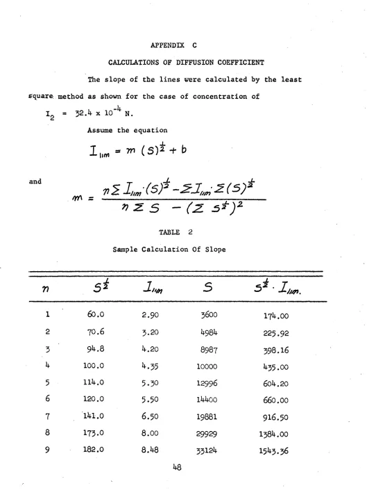
APPENDIX C
CALCULATIONS OF DIFFUSION COEFFICIENT
The slope of the lines were calculated by the least
square, method as shown for the case of concentration of -1*
I « 3 2. k x 10 N.
Assume the equation
1„* - 7,1
b
w . v i i . J s r - s j u m z ( s f
n z. S - (Z s*)z
TABLE 2
Sample Calculation Of Slope
n
5^
hm
S
s* ■
1 60.0 2.90 3600 171*. 00
2 70.6 3.20 1*981* 225.92
3 91*.8 20 8987 398 .16
1* 100.0 **•35 10000 1*35.00
5 lUt.O 5 .3 0 12996 60l*.20
6 120.0 5 .5 0 11*1*00 660.00
7 '11*1.0 6.50 19881 916.50
8 173.0 8.00 29929 138!*. 00
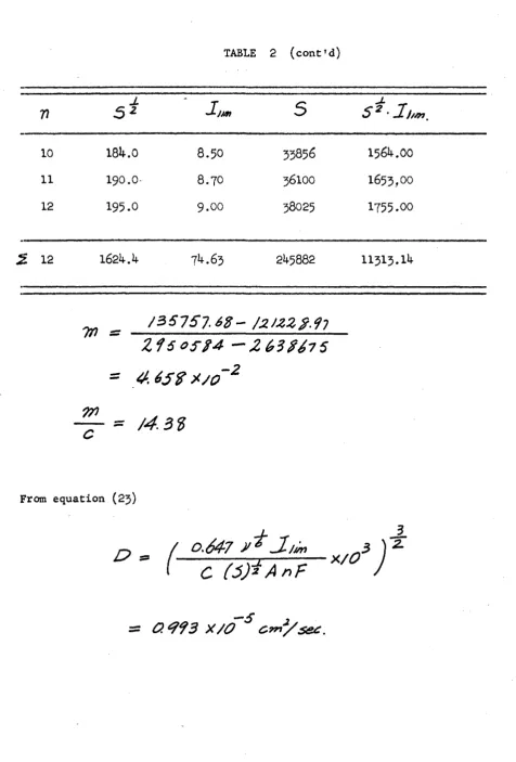
TABLE 2 (cont'd)
77
J.
5
* J-JM 510 184.0 8.50 3585^ 1564.00
11 190.0- 8.70 36100 1653,00
12 195.0 9.00 38025 1755.00
S.
12 162 4.4 7^.63 245882 11313.14^ _
/3 5 7 5 7 .6 S - / 2 U ^ g ^ ^
Z i 5 0S-^4
= 4 . 6 5 $ * ; 0 ~ z
c
=From equation (23)
d _
/
o,6 4 7
^ J - j ™x / 0 3 )
2-1
C ( 5 ) * A n f
50
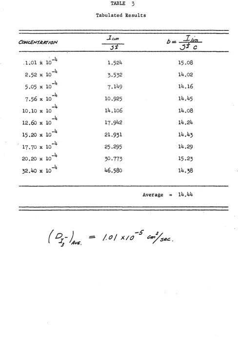
TABLE 5
Tabulated Results
COMCc*T/tfiT/ON
SL/j/n
J,
J *
b — .
J * c
' -if
.1101 x 10 1.52if 15.08
-if
2.52 x 10 3.552 lif .02
-if
5.0 5 X 10 7.1if9 lif .16
-if
7 .5 6 X 10 IO.925 lif. if 5
-if
10.10 x 10 lif.106 lif. 08
~k
12.60 x 10 17.9^2 lif.2if
-if
15.20 x 10 21.931 lif. if 3
-if
I7.7O x 10 25.295 lif.29
-if
20.20 x 10 30-773 15.23
-if
32.if0 x 10 U6.58O lif. 38
APPENDIX D
CALCULATION OF STANDARD DEVIATION
The standard deviation of the experimental term _
R e
called b was calculated from the following equation.
n
2\i
where
S. D. = standard deviation
b . = individual value of b
x
b = means value of b
n = number of values of b
Values of b were taken from Table 3 an<* the calculations of
2
(b^ - b ) were shown in Table
14-TABLE if
- 2
Calculations of (b^ - b)
n b b . - b
i (bt - b)2
1 15.08 -.6if .If 100
2 lif .02 + .If 2 .1770
3 lif. 16 + .28 .0780
if lif.ij-5 -.01 .0001
5 18.08 + • KA CO .1300
TABLE k (cont'd)
52
n b b. - 6
X (b. - b)2
.7 Ur. 1*3 +
.01
.00018 lif. 29 - . 1 5 .0225
9 15.23 - . 7 9 .6250
10 11*. 38 + .16 .025
6
£ 10 11*1*. 1*0 1.5033
S . D .
=(
- A
6*0 3
A
/O -l
'
=s
APPENDIX E
TABLES
54
Table 5
Potential vs. Current
Concentration of = 1 2.6x1 0"Sf Concentration of KI = o.l N
o Disk area = 0 .7 2 8 cm
E volts I ma.
2500 rpm 12500 rpm 20500 rpm 25500 rpm 27500 rpm
0 0 0 0 0 0
0 .0 5 0.65 0.95 0 .9 5 1.05 1'.05
0 .1 0 0 .8 4 1.65 1.65 2 .1 5 2 .1 7
0 .1 5 0 .8 6 1.95 2 .1 0 2 .7 0 2 .7 0
0 .2 0 0.87 2.00 2 .3 5 2.85 2.88
0 .2 5 0.87 2.02 2.4p 2 .9 0 2 .9 5
0 .3 0 0 .9 2 2.02 2 .5 0 2 .9 2 3-00
0 .3 5 0 .9 4 2.05 2.5 5 2 .9 3 3-00
0 .4 0 0 .9 5 2.05 2-5 5 2 .9 4 3.00
0 .4 5 0.96 2.05 2 .5 5 2 .9 5 3-01
0 .5 0 0.96 2.05 2 .5 7 2 .9 5 3.08
0 .5 5 0 .9 7 2.05 2.60 2 .9 7 3-10
0.60 0.98 2 .0 7 2.62 2.9 8 3-1 2
O.65 1.00 2.10 2 .6 4 2.9 9 3 .1 5
0 .7 0 1.02 2.12 2.66 3-00 3 .1 7
0 .7 5 1 .0 4 2 .1 3 2.67 3-02 3-20
0.80 1.13 2 .1 5 2 .7 0 3-05 3.22
O.85 1.20 2 .2 5 2-7 5 3.1 3 3-30
0 .9 0 1 .3 0 2 .4 0 2 .8 4 3 -25 3-4 5
0 .9 5 1 .4 0 2.60 3.06 3.50 3.60
1.00 1.50 2 .7 5 3-33 3.7 0 3.85
1.05 - 3 .0 5 3.7 0 4.10 4 . 2 5
1.10 - 3 .2 5 3-9 5 4 .4 0 4.70
55
Table 6
Effect of Concentration of KI on Limiting Current
-4
Concentration of Ig = 5*05x10 N p
Disk Area = 0-728 cm
E = 0 . 4 volts
J.
S Z X I ma
rpm2
0.0005 N 0.01 N 0.05'N 0 .0 7 5 N 0 . 1 0 N
63.2 - - - - 0.50
70.6 0 .0 9 0.49 0.52 0.52
-83.6 - _ - 0.66
100.0 0 .0 9 0.59 0.74 0.72 0.78
109.5 - - - 0.82
119.5 - - - - O.85
122.5 0.10 0 .6 4 0.88 0.88
-134.0 - - - - 0 . 9 5
1 4 1 -5 0.10 0.67 1.00 1.03 1.03
158.2 0.10 0.69 1.13 1.12
-161.O - - - - 1 .1 7
17 3 .0 0.10 0.71 1.23 1.20 1 .2 7
1 7 9 .0 - - - - 1 .3 0
1 8 4 .0 - - - - 1 -3 5
187.O 0.10 0.71 1.35 1.28