© Owned by the authors, published by EDP Sciences, 2015
Effect of micromorphology of cortical bone tissue on crack propagation
under dynamic loading
Mayao Wang, Xing Gao1, Adel Abdel-Wahab1, Simin Li1, Elizabeth A. Zimmermann, Christoph Riedel2, Bj¨orn Busse2,
and Vadim V. Silberschmidt1,a
1Loughborough University, Leicestershire LE11 3TU, UK
2University Medical Center Hamburg-Eppendorf, Lottestr. 59, 22529 Hamburg, Germany
Abstract. Structural integrity of bone tissue plays an important role in daily activities of humans. However, traumatic incidents such as sports injuries, collisions and falls can cause bone fracture, servere pain and mobility loss. In addition, ageing and degenerative bone diseases such as osteoporosis can increase the risk of fracture [1]. As a composite-like material, a cortical bone tissue is capable of tolerating moderate fracture/cracks without complete failure. The key to this is its heterogeneously distributed microstructural constituents providing both intrinsic and extrinsic toughening mechanisms. At micro-scale level, cortical bone can be considered as a four-phase composite material consisting of osteons, Haversian canals, cement lines and interstitial matrix. These microstructural constituents can directly affect local distributions of stresses and strains, and, hence, crack initiation and propagation. Therefore, understanding the effect of micromorphology of cortical bone on crack initiation and propagation, especially under dynamic loading regimes is of great importance for fracture risk evaluation. In this study, random microstructures of a cortical bone tissue were modelled with finite elements for four groups: healthy (control), young age, osteoporosis and bisphosphonate-treated, based on osteonal morphometric parameters measured from microscopic images for these groups. The developed models were loaded under the same dynamic loading conditions, representing a direct impact incident, resulting in progressive crack propagation. An extended finite-element method (X-FEM) was implemented to realize solution-dependent crack propagation within the microstructured cortical bone tissues. The obtained simulation results demonstrate significant differences due to micromorphology of cortical bone, in terms of crack propagation characteristics for different groups, with the young group showing highest fracture resistance and the senior group the lowest.
1. Introduction
Bone has a highly heterogeneous structure at a micro-scale level, consisting of Haversian canals, osteons, cement lines and an interstitial matrix. This unique microstructure is essential not only for the daily functionality such as the exchange of nutrition and substance, but also for the physical strength and rigidity of bones. However, aging and degenerative bone diseases can increase the risk of bone-related injuries, which can influence mobility and the quality of life. These two conditions can directly affect the balance of a remodelling process leading to a change of micro-morphology and quality of microstructural constituents. In previous research, bone mineral density (BMD) method [15] was mainly used to evaluate the toughness of cortical bone. It is well known that factors such as disease and aging could reduce bone mineral density [1]. Wachter [2] further pointed out that the BMD has a positive correlation with a yield stress and an overall osteonal area. Therefore, bone specimens from senior and diseased groups behave more fragile than those from a health group. Still, though measurements using only BMD give an imperial relationship between the overall bone’s mineral density and its fracture risk, it could not predict a fracture process accurately at the micro-level. Therefore, in recent
aCorresponding author:V.Silberschmidt@lboro.ac.uk
papers, the distribution of micro-structural constituents of cortical bone became a main target to understand its fracture behaviour related to heterogeneity properties of bone [9,14,16,17]. Experiments employed in these studies included both scanning electron microscopy (SEM) [16] and nanoindentation [17] to analyse microstructural constituents of human cortical bone and their mechanical properties, in order to understand theirs functions and mechanisms in the fracture process. Watanabe [3] tested with X-ray and light microscopy cortical-bone specimens of 72 male and 26 female cadavers’ donors, whose age range was from 9 to over 90. The morphological size of osteons and Haversian canals was measured, using collection data to estimate the age of bone. Their result showed that the number of osteons increased with age, while their volume fraction decreased. According to Busse’s [4] investigation, the area of Haversian canals in cortical bone grew persistently with the increase of age, resulting in a higher porosity ratio and a lower osteonal ratio in the senior group. In addition, Busse and his group [5] pointed out that different remodelling processes between the senior and young groups could further widen the difference in the porosity ratio between these groups. In the Bernhard’s study [6], the dimensions of osteons from four groups, including young, senior, diseased and medically treated ones, were measured and compared with each other. The result showed that the young group had
a smallest size of Haversian canals and the largest size of osteons, while the diseased group had the opposite result.
A better understanding of the effect of micromor-phology on bone’s behaviour could be achieved with advanced numerical simulations. A numerical study of the crack propagation in heterogeneous materials is a rather challenging task that requires adequate modelling tools. One of the most suitable approaches is an extended finite-element method (X-FEM) that was introduced by Belyschko and Black in 1999 [7]. Since then, it has been used increasingly in simulation of discontinuity problems such as crack propagation. It employs a locally enriched element area to handle a numerical singularity associated with crack opening thus eliminating a need for remeshing. The authors [8,9] employed X-FEM to study the function of cement lines in bone fracture. Budyn et al. [12] developed a multiple scale statistical X-FEM simulation method to evaluate crack propagation of cortical bone under uniaxial tension. In another study, the authors [9, 18] utilized X-FEM to evaluate the facture behaviour of cortical bone under three-point bending. However, our previously developed models were based on animal (bovine) bones; there is yet a validated human bone model to have. Additionally, quantitative correlations between the type and distribution of microstructural constituents and the fracture behaviour of human cortical bones in different groups are still unknown. Therefore, in this paper, images from four groups originated from University Medical Center Hamburg-Eppendorf in Germany were measured using Image-Pro and Photoshop software. Then, the data was analysed to establish statistical bone models. Finally, numerical simulations with X-FEM were used to simulate the facture behaviour of cortical bone under dynamic loading condition to understand the relationships between microstructural constituents and crack propagation.
2. Materials and methods
2.1. Materials
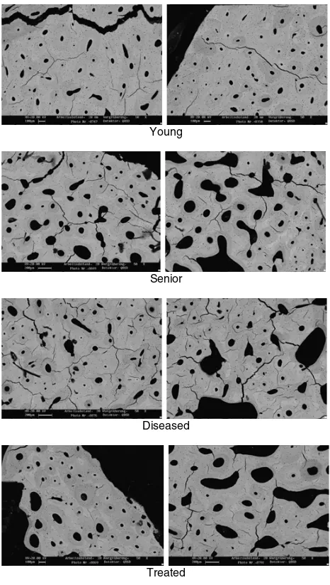
Cortical-bone specimens acquired from proximal femoral diaphysis (female donors, age between 24 and 88) was scanned using SEM through the horizontal cross-section after the grinding and polishing process [6]. The images can be divided into four groups with two images of each group: young group, senior group, diseased group and medically treated group, as shown in Fig.1.
2.2. Analysis method
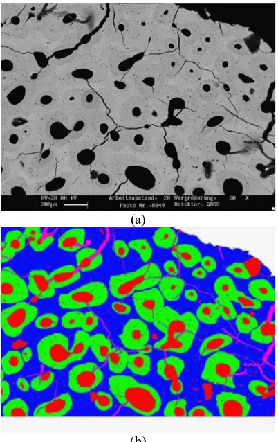
The first step of analysis was to evaluate the volume fractions of microstructural constituents of cortical bones. In order to calculate them accurately, dark edges around the captured images were removed with software prior to measurements to eliminate the effect on porosity. Then, the contrast of images was enhanced to facilitate the differentiation between different micro-constituents using a combination of image process, image automatic recognition and manual operations. In Fig.2, the original and enhanced images demonstrate clearly that red, green, blue and purple represent porosity (resorption cavities, Haversian canals and osteocytes), osteonal areas,
Young
Senior
Diseased
Treated
Figure 1. Micro-images of human cortical bones in transverse section of four groups.
interstitial matrix and microcracks, respectively. Then, the overall number of pixels of various colours could be obtained to estimate the volume fractions of micro-structural constituents. In the next step, the size of individual osteons (approximated with elliptical shapes), including dimensions of their long/short axes and the radius of Haversian canals, were measured accurately using Image-Pro software (Fig. 3). Then, the evaluation process utilises mathematical functions to approximate (with best-fit functions) the distribution of each measured parameters statistically (Fig.4). Finally, these parameters were used as inputs to developed models of human cortical bones with randomly distributed microstructural elements for four studied groups.
3. Model data
(a)
(b)
Figure 2.Calculation method of volume fraction using Image-Pro and Photoshop software: initial (a) and enhanced (b) images.
Figure 3. Method of measuring morphological parameters of individual osteons.
model was established according to the Izod test configuration shown in Fig.5[11].
The cortical-a bone specimen was modelled as rectangular area with a pre-notch. The specimen was divided into two domains: a microstructured area of 1.278 mm in length and 0.958 mm in width as an area of interest was embedded in front of the pre-notch into a homogenized bone material domain (50 mm in length and 8 mm in width) to reduce the overall computational cost. Following the setup of the Izod test, the loading
Figure 4.Statistical distribution of magnitude of long axis for osteons in aged group.
326.8 mm
49.12 mm
1.278 mm
0.985 mm
Figure 5.Models of hammer size and microstructured domain in front of initial notch.
Figure 6. Volume fractions of microstructure constituents of human cortical bone for four groups.
Table 1. Material properties of microstructural constituents of cortical-bone tissue and homogenous material [12,19–21].
Strain Elastic Poisson’s energy-release Model modulus (GPa) ratio rate (N/mm)
Homogeneous 10.46 0.167 0.422
material
Osteon 9.13 0.17 0.86
Interstitial matrix 14.122 0.153 0.238
Cement line 6.85 0.49 0.146
Table 2.Average sizes of individual osteons.
Long axis Short axis Haversian (µm) (µm) canal (µm)
Young 219.48 159.8 20.77
Senior 222.5 170.7 43.57
Diseased 205.52 172.28 34.24
Treated 212.52 185.08 30.36
conditions. The element type used in this simulation was 4-node bilinear plain-strain quadrilateral (CPE4R) ele-ment. The mechanical properties of different microstruc-tural constituents, such as osteons, interstitial area, and cement line were based on the authors’ previous research [9]. The elastic modulus of cement line was 25 percent lower than that of the osteon following the suggestion in Budyn’s paper [12].
These simulations were based on the damage initiation and evaluation criteria of X-FEM using a cohesive traction- separation law. The initial horizontal notch with the length of 300 µm was embedded into the homogenized area next to the microstructural area (Fig.5). The damage in this model was determined based on the elastic-plastic fracture mechanics with the critical maximum principal strain of 0.6% [9] and strain energy release rate in Table1.
4. Results and discussion
In this study, the results from the analysis showed that the young group had the highest fraction of osteonal area (60.03%), but with the lowest porosity (5.96%) and interstitial area (34.01%). However, the fraction of osteonal area in the senior group was 40.79%, lowest of all groups, while the volume fraction of interstitial area was the highest (41.11%).
The volume fraction of porosity in the diseased group was the second-lowest (after the young group), only 15.22%, lower than that for the senior (18.10%) and the treated groups (17.13%). The results demonstrated that the senior group had the higher porosity area and lower osteon area than the young group [4].
For individual osteons, the radius of Haversian canals in the young group was the lowest (20.77µm) of the four groups leading to the lowest fraction of porosity. The senior group had the highest size of the long axis – about 222.5µm, while the highest size of the short axis was in the treated group: 185.08µm. The results for the volume fractions and the size of individual osteons reflected the
(a)
(b)
(c)
(d)
Figure 8.Evolution of crack length during impact.
fact that the aging process and diseases could influence the balance of the remodelling process and directly affect the morphological parameters of osteons.
Four models with different statistical realizations based on the experimental measurements were developed using random distributions of microstructural constituents. The numerical results (Fig. 7) indicated that the crack propagation paths were different in bones of different groups, due to variations in distributions of micro-structural constituents. Crack paths in the four groups demonstrated different crack deflection characteristics [13], with the young group having the least crack deflection path of all other groups. For the diseased and treated groups, the crack paths demonstrated more deflections kinks comparing to the other two groups.
The crack propagation process was additionally influenced by cement lines, and cracks tended to grow through Haversian canals. Previously it was indicated that the presence of cement lines may prevent the crack from destroying other Haversian system during fracture process [14].
Comparing the evolution of crack length with time during the impact for all the groups, the difference was not large, with a standard deviation of 6.75% for the four groups, with an average crack length of 1.419 mm. Among the groups, the young group had the lowest crack length (1.37 mm), while it took the longest time for the crack to propagate through the microstructured area. This means that the structure and parameters of the microstructural constituents in this group resisted the crack propagation through the cortical bone. According to the trend lines for the four groups, the senior group had the lowest toughness, while the young group the highest.
During the first 0.1 ms, the four groups had a similar crack growth rate, while later the senior group demonstrated a higher crack growth rate. Apart from the senior group, the similar trends of crack propagation were noticeable in other three groups up to a crack length of some 0.4 mm; then, the crack in the diseased group grew quicker while the young and treated groups had comparable rates of crack propagation, demonstrating a considerable improvement over the diseased group. The
result shows that micromorphology of individual osteons plays a key role in influencing the crack propagation during the facture process of the cortical bone tissue.
5. Conclusion
The relationships between the micromorphology of microstructural constituents of cortical bone and crack propagation under dynamic loading conditions were investigated using the X-FEM simulation method. The statistical characteristics of volume fractions and sizes of microstructural constituents changes due to aging, disease and medication. These morphological changes could affect features of the crack propagation under dynamic loading conditions, such as the deflection crack path and – as in case of cement line – prevent the crack from damaging the bone tissue. Analysis of crack growth with time reflects that the young and treated groups have a higher resistance capability to the crack growth in the cortical bone than the senior and diseased groups. The treated group showed a considerable improvement in this regard compared to the diseased group.
References
[1] M. Grynpas, Calcif. Tiss. Intern. 53(1), S57–S64 (1993).
[2] N.J. Wachter, G.D. Krischak, M. Mentzel, M.R. Sarkar, T. Ebinger, L. Kinzl, L. Claes, P. Augat, Bone 31(1), 90–95 (2002).
[3] Y. Watanabe, M. Konishi, M. Shimada, H. Ohara, S. Iwamoto, Forens. Sci. Intern.98(1), 55–65 (1998). [4] B. Busse, M. Hahn, T. Schinke, K. P¨uschel, G.
N. Duda, M. Amling, J. Biomed. Mater. Res. Pt A,92(4), 1440–1451 (2010).
[5] A. Bernhard, P. Milovanovic, E. A. Zimmermann, M. Hahn, D. Djonic, M. Krause, S. Breer, K. P¨uschel, M. Djuric, M. Amling, B. Busse. Osteop. Intern.24(10), 2671–2680 (2013).
[6] D. Mulhern, M. Rib. Amer. J. Phys. Anthrop.111(4), 519–530 (2000).
[7] T. Belytschko, T. Black, Int. J. Numer. Meth. Engng. 45(5), 601–620 (1999).
[8] A.A. Abdel-Wahab, A.R. Maligno, V.V. Silber-schmidt, Comput. Mater. Sci.52(1), 128–135 (2012). [9] S. Li, A. Abdel-Wahab, E. Demirci, V. V.
Silber-schmidt, Int. J. Fract.184(1–2), 43–55 (2013). [10] E. Budyn, T. Hoc, J. Jonvaux, Comput. Mech.42(4),
579–591 (2008).
[11] A.A. Abdel-Wahab, V.V. Silberschmidt, Eur. Phys. J. Special Topics206(1), 41–50 (2012).
[12] E. Budyn, T. Hoc, Eur. J. Comput. Mech. /Rev. Eur. Num´er.16(2), 213–236 (2007).
[13] M.E. Launey, M.J. Buehler, R.O. Ritchie, Ann. Rev. Mater. Res.40, 25–53 (2010).
[14] S. Mohsin, F.J. O’Brien, T.C. Lee, J. Anat. 208(1), 81–89 (2006).
[16] S. Mischinski, A. Ural, Computer Meth. Biomech. Biomed. Engng16(1), 81–94 (2013).
[17] J.Y. Rho, M.E. Roy, T.Y. Tsui, G.M. Pharr, J. Biomed. Mater. Res.45(1), 48–54 (1999).
[18] S. Li, A. Abdel-Wahab, V.V. Silberschmidt, Engng Fract. Mech.110, 448–458 (2013).
[19] J.L. Katz, H.S. Yoon, S. Lipson, R. Maharidge, A. Meunier, P. Christel, Calcif. Tiss. Intern. 36(1), S31–S36 (1984).
[20] R.O. Ritchie, J.H. Kinney, J.J. Kruzic, R.K. Nalla, Fatigue Fract. Engng Mater. 28(4), 345–371 (2005).
![Table 1. Material properties of microstructural constituents ofcortical-bone tissue and homogenous material [12,19–21].](https://thumb-us.123doks.com/thumbv2/123dok_us/8176487.1365569/4.595.327.522.65.730/table-material-properties-microstructural-constituents-ofcortical-homogenous-material.webp)

