ABSTRACT
DUFFICY, MARTIN KYLE. Binders and Hosts for High-Capacity Lithium-ion Battery Anodes. (Under the direction of Dr. Peter S. Fedkiw and Dr. Saad A. Khan).
Lithium-ion batteries (LIBs) are universal electrochemical energy storage devices that
have revolutionized our mobile society. Nonetheless, societal and technological advances drive
consumer demand for LIBs with enhanced electrochemical performance, such as higher charge
capacity and longer life, compared to conventional LIBs. One method to enhance LIB
performance is to replace graphite, the industry standard anode since commercialization of
LIBs in 1991, with high-charge capacity materials. Implementing high-capacity anode
materials such as tin, silicon, and manganese vanadates, to LIBs presents challenges;
Li-insertion is destructive to anode framework, and increasing capacity increases structural strains
that pulverize anode materials and results in a short-cycle life. This thesis reports on various
methods to extended the cycle life of high-capacity materials. Most of the work is conducted
on nano-sized anode materials to reduce Li and electron transport pathway length (facilitating
charge-transfer) and reduce strains from volume expansions (preserving anode structure).
The first method involves encapsulating tin particles into a graphene-containing carbon
nanofiber (CNF) matrix. The composite-CNF matrix houses tin particles to assume strains
from tin-volume expansions and produces favorable surface-electrolyte chemistries for stable
charge-discharge cycling. Before tin addition, graphene-containing CNFs are produced and
assessed as anode materials for LIBs. Graphene addition to CNFs improves electronic and
mechanical properties of CNFs. Furthermore, the 2-D nature of graphene provides Li-binding
graphene-containing CNF electrodes that lead to increased capacity retention. Of note,
electrodes containing ≤ 20 wt% tin result in small tin (metallic and tin oxide) particles (≤ 15
nm) within the composite-CNF matrix, which yield long cycle-lives; large reversible capacities of ~ 600 mAh g-1 are observed at 0.2-C rates, while capacities of ~ 400 mAh g-1 (double the capacity of CNFs) are observed after hundreds of cycles at 2-C rates.
The second method comprises an approach to enhance the cycle life of silicon anodes.
Many researchers believe that Si is the future anode material of LIBs, and Si is capable of
providing a much needed boost in overall cell performance. Silicon has the highest known
charge capacity at ~ 3579 mAh g-1, nearly an order of magnitude larger than graphite (372 mAh g-1). In attempt to realize the entire capacity of Si anodes, we use binding agents to prolong cycle life. Binding agents enhance capacity retention via favorable interactions with
cell components such as active materials and electrolytes. In this study, we introduce
galactomannans (specifically, guar) as viable, inexpensive, biopolymer binders for Si
electrodes. In attempt to elucidate the role of the binder in Si electrodes, we study
guar-electrode and -electrolyte interactions that lead to electrochemical performance enhancements.
We recognize that there are deficiencies in guar-silicon systems, which we address in our
following approach. Notably, we develop a guar-derived binder to increase the strength and
conductivity of Si-based electrodes by crosslinking guar and carbon black dispersions. The
crosslinked binders, in effect, enhance electrode adhesion and hinder electrode cracking by
self-healing. This study monitors gelation via rheological methods and assesses effects of
to enhance electrochemical performances. X-ray diffraction studies enable us to suggest a
Li-insertion mechanism, where Li travels through large channels created by defects in the crystal
structure. The ensuing manganese vanadate structure produces a stable framework that results
in stable cycling of hundreds of cycles.
© Copyright 2016 Martin Kyle Dufficy
Binders and Hosts for High-Capacity Lithium-ion Battery Anodes
by
Martin Kyle Dufficy
A dissertation submitted to the Graduate Faculty of North Carolina State University
in partial fulfillment of the requirements for the degree of
Doctor of Philosophy
Chemical Engineering
Raleigh, North Carolina
2016
APPROVED BY:
_______________________________ _______________________________
Dr. Peter S. Fedkiw Dr. Saad A. Khan
DEDICATION
I dedicate this work to my father, Joe Dufficy, who taught me to push the boundaries
BIOGRAPHY
Martin Kyle Dufficy was born just outside of Chicago in Evanston, Illinois. He grew
up in the suburb of Skokie and spent much of his childhood traveling around the Chicagoland
Area playing soccer matches. Upon realization that a career in professional soccer was not in
the cards, Marty turned towards the books. His favorite high school classes were calculus and
chemistry, which influenced his decision to pursue a degree in Chemical Engineering.
Marty enrolled at Iowa State University, located in the lovely town of Ames. While at
Iowa State, Marty took on a nine month co-op as a process engineer with International Paper
in Cedar Rapids, Iowa. Interested in exploring other career paths of chemical engineer, Marty
decided to pick up undergraduate research. Under the direction of Robert Brown and Brett
Shanks, Marty characterized and assessed the performance of catalysts for steam reforming
and deoxygenation of biomaterials for biorenewable chemical production. Marty worked in
many different laboratory settings including Ames National Lab, Iowa State University, and
even a stint at Fritz Haber Institute of the Max Plank Society in Berlin, Germany. His passion
to advance science and question the status quo brought him to graduate school.
Marty joined the groups of Saad Khan and Peter Fedkiw at North Carolina State
ACKNOWLEDGMENTS
I would like to thank my advisors Saad Khan and Peter Fedkiw for their guidance
throughout graduate school. Their tutelage taught me to communicate in clear and concise
manner, and to see the work of myself and others in a new light. I would also like to thank my
group members, past and present: Andrew Loebl for teaching me the basics of battery assembly
and analysis early into my Ph.D., Shengyang Huang for assisting in materials characterization,
Mackenzie Geiger for many fruitful discussions on rheology, and Kimberly Dennis for her
arduous work in the lab. I would also like to thank the folks at the Analytical Instrumentation
Facility for assisting with materials characterization, notably Fred Stevie for running XPS and
Li Liu for his wizardry with TEM. I would like to thank the professors in this department for
allowing me to use their equipment: Greg Parsons and Jan Genzer. I would also like to thank
our collaborators in the Department of Chemistry, Lan Luo and Paul Maggard, for broadening
my horizons and introducing me to new Li-ion chemistries.
My friends and colleagues at NC State have been a tremendous source of innovation,
inspiration, and invitation. Graduate school would not have been the same without all the
amazing people I have met. I would like to thank the people with whom I share a roof: Matt
Melillo and Ryan Barton for their camaraderie through the journey of graduate school; Cody
Addington for footing the Netflix bill and encouraging engineering around the house; Ellie the
dog for being a happy oversized lap and exercise companion. I would also like to thank the
cycling crew for providing me an outlet to experience the beauty of the Carolinas—from
I would like to give thanks to my family: to my parents Judy and Joe, thank you for
stressing the importance of education and balance in life; to my brother Nick for instilling in
me a competitive spirit; and to my sister Annie for her support and always putting a smile on
my face.
Last, but certainly not least, I would like to thank my girlfriend, Margaret Spinks, for
being a truly great partner-in-crime, for sharing my interests and making life fun. Also, many
thanks for making the coffee to fuel my mornings and for making some of the best lunches to
TABLE OF CONTENTS
List of Tables ... x
List of Figures ... xi
Chapter 1. Introduction ... 1
1.1. Opening Remarks... 2
1.2. Document Organization ... 4
1.3. References ... 6
Chapter 2. Background ... 7
2.1. The Li-ion Battery... 8
2.1.1. Electrochemistry of Li-ion anodes ... 10
2.1.2. Carbon Anodes... 16
2.1.3. Manganese Vanadate Anodes ... 21
2.1.4. Tin-based Anodes ... 22
2.1.5. Silicon Anodes ... 25
2.1.6. Binding agents ... 27
2.2. Galactomannans ... 30
2.2.1. Guar solution and gels ... 32
2.2.2. Oscillatory rheology and gel formation ... 33
2.3. Electrospinning ... 35
2.3.1. The Process ... 36
2.3.2. Electrospinning parameters ... 38
2.3.3. Steady-shear rheology and fiber morphology ... 40
2.3.4. Polymer and carbon fibers via polyacrylonitrile ... 41
2.3.5. Composite carbon nanofibers ... 44
2.4 References ... 45
Chapter 3. Hierarchical graphene-containing carbon nanofibers for lithium-ion battery anodes ... 55
3.1. Introduction ... 56
3.2. Materials and Methods ... 59
3.2.1. Graphite oxide preparation ... 59
3.2.4. Graphene-containing nanofibers preparation ... 60
3.2.5. Composite polymer and CNF characterization ... 61
3.2.6. Electrochemical performance characterization ... 62
3.3. Results and Discussion ... 63
3.3.1. GO/PAN nanofibers by electrospinning ... 63
3.3.2. TRGO/CNF characterization ... 68
3.3.3. TRGO/CNF electrochemical characterization ... 73
3.4. Summary ... 82
3.5. References ... 83
Chapter 4. Effects of Composition and Structure on Performance of Tin/Graphene-Containing Carbon Nanofibers for Li-ion Anodes ... 88
4.1. Introduction ... 90
4.2. Experimental ... 92
4.2.1 Preparation of electrospinning solution ... 92
4.2.2 Preparation of Sn-containing fibers ... 92
4.2.3 Characterization of Sn-containing fibers ... 93
4.2.4 Electrochemical characterization ... 94
4.3. Results and Discussion ... 95
4.3.1 Characterization of Sn-fibers ... 95
4.3.2 Electrochemical characterization of Sn-containing fibers ... 105
4.4. Summary ... 115
4.5. References ... 117
Chapter 5. Galactomannan binding agents for silicon anodes in Li-ion batteries... 120
5.1. Introduction. ... 121
5.2. Experimental ... 124
5.2.1. Materials ... 124
5.2.2. Binder purification and dissolution ... 125
5.2.3. Half-cell fabrication ... 125
5.2.4. Electrochemical testing ... 126
5.2.5. Solvent Uptake ... 127
5.4. Summary ... 142
5.5. References ... 143
Chapter 6. Guar hydrogel binders for silicon nanoparticle anodes: a case study of binder rheology on electrode performance ... 146
6.1. Introduction ... 148
6.2. Materials and Methods ... 150
6.2.1. Guar purification ... 150
6.2.2. Hydrogel preparation ... 151
6.2.3. Hydrogel characterization ... 153
6.2.4. Electrochemical characterization ... 154
6.3. Results ... 155
6.3.1. Gelation rheology... 155
6.3.2. Materials characterization ... 163
6.3.3 Electrochemical characterization ... 169
6.4. Summary ... 177
6.5. References ... 179
Chapter 7. Vacancy-Induced Manganese Vanadates and Their Potential Application to Li-ion Batteries ... 184
7.1. Introduction ... 185
7.2. Experimental Section ... 186
7.2.1. Materials and Instrumentation ... 186
7.2.2. Synthetic Procedures. ... 187
7.2.3. Electrode Fabrication and Characterization. ... 188
7.2.4.Ex-Situ Electrode Characterization... 188
7.3. Results ... 189
7.3.1. Crystallographic characterization ... 189
7.3.2. Electrochemical characterization ... 191
7.4. Summary ... 199
7.5. References ... 200
Chapter 8. Conclusions and Recommendations for Future Work ... 202
8.2.1. Electrospun carbon nanofiber anodes ... 206
8.2.2. Tin anodes ... 212
8.2.3. Coating nano-Si anodes ... 212
8.2.4. Binders for Si anodes ... 213
8.2.5. Manganese vanadate anodes ... 221
8.3. References ... 223
Appendices ... 227
Appendix A: Supporting Information for Chapter 4 ... 228
Appendix B: Supporting Information for Chapter 5 ... 238
Appendix C. Supporting Information for Chapter 6 ... 248
Appendix D: Supporting Information for Chapter 7 ... 257
D.1. Data Analysis ... 258
D.1.1. Estimating mols Li on first lithiation. ... 258
D.1.2. Thermogravimetric analysis ... 258
D.1.3. Infrared spectra ... 258
D.2. Figures and Tables ... 259
LIST OF TABLES
LIST OF FIGURES
1.1. Opening Remarks
Rechargeable batteries were first invented in 1859, when Gaston Planté devised the
lead acid battery. At the time, Planté used cloth to separate lead sheets that he submerged in
sulfuric acid. Throughout the years, technological developments led to the modern lead acid
battery found in many internal combustion engine vehicles, and exploration of new chemistries
led to Ni-Cd and Ni-H rechargeable batteries. However, these early battery chemistries did not
compare to the specific energy and electrochemical potential of lithium. Short-circuiting in
metallic lithium anodes plagued early renditions of Li-batteries. Major contributions headed
by Goodenough, Whittingham, and Yazami in the 1970-80s led to a battery where Li-ions
reversibly shuttled across two electrodes that did not comprise metallic lithium. [1] With successful commercialization of Li-ion batteries (LIBs) in 1991, Sony revolutionized our
mobile society. Today, LIBs power many mobile devices such as phones, laptops, and more
recently, electric vehicles. Nonetheless, an increased energy density is needed for electric
vehicles to competitively compete with the internal combustion engine market.
Since commercialization 25 years ago, the cycle life of LIBs has significantly improved
and the cost to produce LIBs has significantly decreased, [2] which is advantageous for stationary applications. However, the gravimetric energy density (advantageous for mobile
applications) has only increased ~ 2.5 times in the same 25-year period; LIBs in 1991 contained
energy densities of ~ 100 Wh kg-1, whereas today’s state-of-the-art LIBs contain ~ 250 Wh kg -1. Performance enhancements are largely attributed to discovery of novel cathode materials.
Promising high-charge capacity materials such as tin, silicon, and metal oxides provide
alternatives to graphite anodes. Incorporating theses high-capacity anode materials in LIBs
may increase energy density as high as 30 %, rendering the range of an electric vehicle
comparable to a full tank of gas. [3] However, high-capacity materials suffer from a short cycle life. Here, we investigate means to enhance the cycle life of high-capacity anode materials.
The work comprised in this thesis largely focuses on implementing high-capacity Si-
and Sn-based anode materials on the nano-scale to enhance the cycle life of next-generation
anodes. We consider nanomaterials as replacements for conventional micron-sized active
materials in Li-ion batteries because they improve redox kinetics, charge-transfer, and
structural integrity. We couple use of nanomaterials with approaches to vary: 1) architecture,
by using structures such as nanofibers, nanoparticles, or nanowires; 2) composition, by forming
nano-composites with carbon, a material known to exhibit stable electrochemical performance
in LIBs; 3) binding agent, which may favorably associate with electrode materials. Unique,
multifaceted methods to enhance electrochemical performances arise from our combinatorial
approach. Notably, we investigate composite-carbon nanofiber/tin and Si/binder systems to
extend the cycle life of high-capacity anodes in LIBs. The last study in the document
investigates a less-considered, high-capacity transition metal oxide for potential high-power
anodes: manganese vanadates. Unlike the aforementioned methods used to prolong the cycle
life of Si- and Sn-based anodes, here we assess how defects in molecular structure may be used
1.2. Document Organization
This dissertations begins with a background section (Chapter 2), in which we review LIB electrochemistry and survey present and future electrode materials for next-generation
LIBs: from Li-active hosts to binding agents. This chapter highlights electrochemical methods
used to characterize these electrode materials. Proceeding sections summarize the
electrospinning fiber-formation process and present recent developments from nanofiber
literature. Subsequent chapters (Chapters 3 - 7) provide results from various approaches used to extend the cycle life of promising, high-capacity anode materials. All studies aim to correlate
physical with electrochemical properties to produce next-generation Li-ion anodes.
The first approach involves encapsulating tin nanoparticles within a
graphene-containing carbon nanofiber matrix. Tin has a capacity three times greater than commercial
graphite anodes, but suffers from a short life due to particle pulverization. In this study, we
used carbon nanofibers to provide scaffolding and prevent cracking of tin particles during
cycling. Graphene, an electronically conductive and flexible two-dimensional carbon, was
added to the carbon nanofibers to enhance electronic properties of the composite electrode for
high-rate capabilities. Before introduction of tin, graphene-containing carbon nanofibers were
produced and assessed as conductive, high-capacity anodes (Chapter 3). Here, we scrutinized effects of graphene concentration on fiber morphology and structure. The aforementioned
physical properties were correlated with electrochemical performance. Incorporation of tin in
parameters, such as tin concentration and thermal treatment temperature, on
composite-nanofiber morphology and tin oxidation state. The goal of this study was to produce an
electrode capable of high-capacity, stable cycling in Li-ion batteries by encapsulating tin
nanoparticles into graphene-containing carbon nanofibers.
Next, we shift attention to Si-based systems. Silicon has the highest charge capacity of
any known material, but suffers from particle pulverization that ends in cell failure (similar to
tin). Unlike the first approach, where we used carbon composites to increase the cycle life, a
novel biopolymer binding agent is used to increase the cycle life of silicon nanoparticle (SiNP)
systems. Binding agents bond with electrode components to preserve microstructure and
decrease internal resistances across the electrode. Chapter 5 showcases galactomannans as novel binding agents for SiNP electrodes. Here, we examine galactomannanelectrode and
-electrolyte interactions that lead to electrochemical performance enhancements in Si-based
anodes. Appendix B contains supplemental information on Si-galactomannan systems, including further assessment on Si-binder interactions. We recognized that galactomannans
(specifically guar gum) did not make perfect binders, and in Chapter 6, we showcase crosslinked guar-carbon black hydrogel binders, which were developed to build upon
shortcomings in our previous study. Notably, we attempt to increase the strength and
conductivity of Si-based electrodes. The crosslinked binders, in effect, enhance electrode
cohesion and hinder cracking by self-healing. This study monitors gelation via rheological
methods and assesses effects of crosslinking density on physical and electrochemical
Our final study, reported in Chapter 7, comprises a preliminary investigation on a novel manganese vanadate, which has potential application as anode material in LIBs
(Appendix D contains supplementary information). Typical manganese vanadate anodes suffer from a short cycle life and poor electronic conductivity, and thus, researchers overlook
manganese vanadates for carbon, Si, and Sn. To enhance the cycling performance of
manganese vanadates, we investigate a novel crystal conformation with induced structural
vacancies. We assess structure as a function of state-of-charge and the electrochemical
performance of the novel vacancy-induced anode.
The dissertation concludes (Chapter 8) with a summary of major findings in each chapter and a prospective means to progress work presented in this document. In this chapter,
we address the viability of carbon nanofiber anodes, Si-based systems, and manganese
vanadate anodes in LIBs. This chapter proposes extensions to studies in Chapters 3 – 7, with aim to extend the cycle life of high-capacity anode materials. We hope our studies will
encourage use of multifaceted approaches for incorporation of high-capacity LIB anode
materials, and in effect, enhance battery technology and the quality of our mobile society.
1.3. References
(1) D. Deng. Energy Science & Engineering, 3, 2015, 385-418.
2.1. The Li-ion Battery
Li-ion batteries (LIBs) are ubiquitous electrochemical energy storage devices. The vast
appeal for LIBs, be it for mobile or stationary storage, lies in the high-energy and power
density. [1] Energy density in batteries, or charge per unit mass or volume, is the product of nominal operating voltage and specific capacity. [2] The high-voltage of LIBs, at 3.6 V/cell, decreases the necessary amount of cells in a battery. Lightweight small Li-ions make favorable
charge carriers, while favorable electrodes chemistries boost specific capacities. Modern cells
boast energy densities > 250 Wh kg-1, [3] which is over twice the energy density of other rechargeable battery chemistries such Ni-Cd and Ni-MH. High-power density (rapid withdraw
of current) is also an advantageous property of LIBs, and is related to internal battery
resistance. A high-power density allows for quick acceleration in electric vehicles and adoption
in mobile power tools. Despite the growing usage of LIBs, advancements in consumer
electronics technology drive demand for batteries with enhanced electrochemical performance.
LIB cells comprise three major components: anode, cathode, and electrolyte.
Electrodes are fabricated in a roll-to-roll process, where slurries of binding agents and
composite materials (active material and conductive additive) are cast on a current collector
(metal foil). A cartoon of a Li-ion full cell is shown in Figure 2.1. During a charge cycle, Li-ions transport from cathode to anode through electrolyte (Li-ion flow reverses during
discharge). Current state-of-art LIBs use graphite anodes, Li-rich metal oxide cathodes, and
different approaches to enhance the performance of LIBs such as use of voltage,
high-capacity cathode materials [4] or electrolyte additives. [5] This thesis focuses on a different approach to enhance the performance of LIB: development of energy-dense anodes. The
following subsections provide a literature survey on novel anode components ranging from the
active materials to the binding agents. Since the Li-graphite intercalation reaction occurs at
voltages close to the reduction of Li (deep charging may occur at 0 V vs. Li/Li+), investigating materials with reduction potentials lower than graphite would render little improvement.
Rather, novel active materials that have larger charge capacities than graphite (372 mAh g-1), such as manganese vanadates (~900 mAh g-1), tin (1000 mAh g-1), and silicon (3600 mAh g -1), are analyzed and assessed. High-capacity anodes usually suffer from a short cycle life. To
increase cycle life, electrodes with various architectures and binding agents are investigated.
However, before a literature survey on current and promising anode material for LIB is
Figure 2.1. Cartoon of LIB showing the three major active components (anode, cathode, and electrolyte), as well as the non-active components: Cu/Al-foil current collectors, binders to adhere electrodes to the current collectors, a separator to prevent short-circuiting, and carbon black (CB) as a conductive additive to reduce internal cell limitations
2.1.1. Electrochemistry of Li-ion anodes
Anodes in LIBs store charge, in the form of Li, through redox reactions. Anodes are
defined as electrodes that are oxidized by the flow of electrons in an external circuit. By
definition, LIB anodes vary in polarity from charge to discharge; the anode is the positive
electrode during charge and negative electrode during discharge. While this section focuses on
the electrochemistry of negative electrodes (hereafter referred to as anodes), fundamentals of
cathodes are analogous. The half-cell reactions for industrial-standard graphite anode
forward reactions, Li-ions transport through electrolyte in the cell and are met by electrons that
transports through an external circuit.
Li++ e−+ 6C Charge
Discharge LiC6 (Reaction 2.1)
LiCoO2 Charge
Discharge Li1−𝑥CoO2+ 𝑥Li
++ 𝑥e− (Reaction 2.2)
Unlike capacitors where charge builds on the surface, ions in batteries insert into
Li-active hosts. For example, Li intercalates into layers of graphite in Reaction 2.1. Both Reactions 2.1 and 2.2 are reversible and progress forward on charge cycles and backward on discharge. Since the forward reactions require electrical energy to occur (charge), the system
is an electrolytic cell. An electrolytic cell is defined as a cell having a positive Gibbs free
energy (Equation 2.1):
∆𝐺 = −𝑛𝐹𝐸𝑜 (Equation 2.1)
where G is the Gibbs free energy, n is the number of electrons in the redox reaction, F is Faraday’s constant, and E° is cell voltage that is defined by the species in the reaction (E° =
ECathode - EAnode). If E° > 0 and ΔG < 0, the cell is considered galvanic, the redox reaction occurs
spontaneously, and work is done on the system (i.e. powering a device). Dividing Equation 2.1 by molecular weight of the species yields the cell-specific theoretical energy density. Thus, for energy dense anodes, it is imperative to study materials with 1) low-reduction potentials to
increase Eo and 2) high-capacity to increase n.
Throughout this dissertation, electrochemical performance of anode materials are
electrode comprises metallic Li (E° ≈ -3.05 V vs. SHE). Chronopotentiometry, or
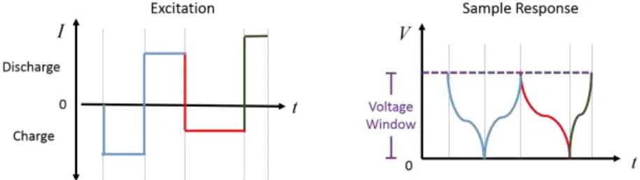
constant-current cycling, is used to charge and discharge the half-cells. In a sample test, the user chooses
a certain current (charge/discharge rate) and measures the voltage within a material-specific
potential window. Figure 2.2 shows sample data obtained by chronopotentiometry. Because one electron is needed to reduce one Li-ion, as shown in Reaction 2.1, the capacity is calculated by integrating current over the time needed to scan the potential window from one
voltage cut-off at to to the other, at tf.
Capacity = ∫ 𝑖 ∙ 𝑑𝑡𝑡𝑓
𝑡𝑜 (Equation 2.2)
Slow currents may be applied to determine a maximum, or theoretical, capacity of
electrodes. Slow currents reduce mass transfer and kinetic limitations. Fast currents may be
applied to assess power capacities of working electrodes. Charging and discharging currents
are expressed as C-rates, and calculated as the quotient of theoretical capacity divided by total
time necessary to obtain full charge or discharge. For example, a 0.5-C rate for a battery with
3600 mAh of capacity would charge in 2 hours at a current of 1800 mA, and a 2-C rate would
charge the same battery in 0.5 hr at 7200 mA. Chronopotentiometry is the first charging step
in commercial LIBs, and is followed by chronoamperometry, where a DC bias is applied until
the current falls below a specified threshold (typically C/100). The efficiency of the anode
(also known as coulombic efficiency) at each cycle is defined as the discharge capacity over
Figure 2.2. The basics of chronopotentiometry: an excitation (current) is applied to a cell and the response (change in voltage) is measured within a voltage limit. The time to span the voltage window is used to calculate electrode capacity. Symmetrical or asymmetrical currents may be applied, where charge and discharge current is constant or varied, respectively.
Graphite is a good candidate for high-energy anodes because Li-ions intercalate near,
but positive to, the potential of Li reduction. However, common electrolyte components are
not thermodynamically stable at the low potentials needed to achieve full intercalation in
graphite electrodes. The electrolyte undergoes a series of reduction and polymerization
reactions below a certain potential (~0.8 V vs. Li/Li+ for commercial electrolytes), which forms a passivating film on the electrode surface about 1-10 nm thick. [7] The passivating film is known as the solid-electrolyte interphase (SEI), [8] and allows for operation of LIBs outside the thermodynamically stable voltage window of electrolytes. Li-ions are able to penetrate
through the SEI because it is ionically conductive. Using impedance spectroscopy, researchers
proposed that the ionically conductive properties of the SEI form at potentials below 250 mV
vs Li/Li+. [9] Electrons, however, have difficultly transporting through the SEI because it is an electronic insulator. The SEI is typically formed on the first cycle, termed a “formation cycle,”
and results in irreversible loss of Li-ions in the electrolyte. Formation of a stable SEI upon the
irreversible capacity loss and electronic isolation of Li-active particles, both of which lead to
premature cell failure. High-capacity and -surface area anodes (porous materials,
nanoparticles, etc) suffer from large irreversible capacity loss. Many approaches are being
taken to limit these capacity losses, such as formation of an artificial SEI [10], or changing the composition of electrode [11] and electrolyte [12]. However, short cycle life and poor capacity retention still hinder these high-capacity and -surface area electrodes from appearing in the
LIB market. A common method used to study SEIs, working electrodes, and interfaces
between the two is electrochemical impedance spectroscopy.
Electrochemical impedance spectroscopy (EIS) is an interfacial technique used to study
the Li-insertion mechanism in batteries. [13] Impedance, Z, is a complex measure of resistance to electron flow in a circuit. It may be thought as an alternating current extension of Ohm’s
law (E = I • R, where E is the voltage, I is the current, and R is the resistance). In a typical
potentio-EIS experiment, a sinusoidal voltage is applied to a steady-state electrode with
varying frequency. The corresponding phase change and amplitude of current are measured at
each frequency to determine the impedance.
The magnitude of impedance and phase angle may be plotted against log frequency,
called a Bode plot, or the imaginary impedance may be plotted against the real component,
called a Nyquist plot. Both plots enable relation of impedance data with electrochemical
phenomena by fitting to equivalent circuits. More specifically, equivalent circuits (i.e. placing
resistors, capacitors, and inductors in series or parallel) allow the user to model Li-insertion by
faradaic events such as charge transfer do not occur at the same frequencies (time constants) [14] as solid-state diffusion. A cartoon of a Nyquist plot and typical equivalent circuit for a
Li-ion half-cell is shown in Figure 2.3. The Nyquist plot below comprises a high-frequency semi-circle, a mid-frequency semi-semi-circle, and a diagonal line at low frequencies. Semi-circles are
typically modeled as parallel QR circuits and diagonal lines are modeled as Q, where Q is a
constant-phase element (non-ideal capacitor). Each component of the equivalent circuit is
related to an electrochemical process; ohmic resistances (dominated by the solution resistances
of the electrolyte, and thus termed RSoln) are measured at high frequencies, a film resistance from the SEI (RSEI) and charge-transfer (RCT) at mid-frequency ranges, followed by diffusion at low frequencies.
An interpretation of the Nyquist plot and equivalent circuit in Figure 2.3 is the following: ohmic resistances from the solution, copper current collector, and electronic
connections are experienced at short times, followed by the flow to the SEI. Li-ions de-solvate
before entering the SEI. [15] Once through the SEI, the electron meets a Li-ion and undergoes charge transfer at the surface of the active material. Li(0) then diffuses through the active
material, which occurs at long time scales, and can be the rate-determining step. [16] It is important to note that all values (resistances, diffusion coefficients, etc.) obtained via EIS are
potential-dependent, as working electrode composition varies with lithiation. When looking at
new materials for LIB anodes, especially those for electric vehicle application, it is important
to minimize internal cell resistances. Realizing a physical interpretation of EIS data suggests
that novel, high-performance anodes must 1) allow the formation of a stable SEI with the
electrolyte, 2) provide ample electronic and ionic conductivity for rapid charge transfer, and
3) contain short diffusion pathways. The next sections highlight conventional and promising
anode materials for Li-ion batteries, beginning with carbons.
2.1.2. Carbon Anodes
Since commercialization of LIBs in 1991, carbon-based materials remain the preferred
choice of anode. The type of carbon (graphitic, amorphous, etc.) heavily impacts the
electrochemical performance of the electrode. While carbon electrodes have been extensively
studied, 14–16 with an emphasis on graphite, current research aims to discover and investigate
novel, high-capacity carbons as active anode material. Herein, attention is given to ordered
Graphite—a layered, crystalline allotrope of carbon–was first discovered as a
reversible anode material for Li-ion batteries by Rachid Yazami in 1983 [17] and is still used in
most LIB anodes today. Success of the graphite anode is attributed to four main features: 1)
Li-insertion near, but positive to, reduction of Li+ to Li(0), 2) structural stability 3)
high-electronic conductivity and 4) favorable reaction kinetics. Graphite has a low-intercalation
potential with Li; the fully lithiated stage of carbon occurs at < 0.1 V vs. Li/Li+ while deep
charging occurs at the reduction potential of Li. [18] The low Li-insertion potential and minimal
voltage hysteresis on charge/discharge profiles contribute to the high-energy and power density
of LIBs. Intercalation at potentials lower than graphite-insertion (< 0 V vs Li/Li+) raise safety
concerns, as Li plating on the surface of graphite may lead to dendrite formation and cell
failure. The low (relative to alloying materials such as Si and Sn) theoretical charge capacity
of graphite, LiC6 = 372 mAh g-1, results in low volume expansions of 10.3% during
Li-intercalation. The van der Walls forces that preserve graphite’s layered structure are able to
withstand the volume expansions of intercalation, which leads to a mechanically durable
electrode and contribute to a long cycle life. Graphite also has anisotropic electronic
conductivity properties, which minimizes ohmic resistances for fast cycling. [16, 19] Graphite
electrodes also have high-columbic efficiency and low-capacity fade, which are attributed to
1) reversibility of the lithium-carbon complex (Reaction 2.1), and 2) formation of a stable
solid-electrolyte interphase (SEI) with carbonate electrolyte solvents, [2] preventing further
that graphite electrodes offer, new forms of carbon materials with enhanced charge capacity
are being explored as alternative anodes. One such material is graphene.
Graphene, an sp2 hybridized two-dimensional (2-D) carbon, has gained a great deal of attention for electrochemical energy storage. Researchers attempt to exploit enticing physical,
chemical, and mechanical properties of graphene for nanoscale electronic materials. These
properties include, but are not limited to, a high-electrical conductivity, specific surface area,
strength, and flexibility. Notably, near-ballistic electron transport [20] in high-quality graphene at room temperatures minimizes the ohmic resistance across electrodes, while high-specific
surface area provides Li more binding sites. Additionally, flexible and mechanically robust
electrodes are able to withstand mechanical stresses of Li-insertion and permit use in wearable
devices. [21] Early reports [22] on graphene anodes revealed a reversible charge capacity of 540 mAh g-1, leading the authors to conclude that lithium does not bind to graphene in the same LiC6 orientation as graphite. Researchers [23] used first-principles calculations to predict a LiC3 stoichiometry for pristine graphene sheets, which increase the specific capacity from the 372
mAh g-1 of graphite to 754 mAh g-1; the 2-D nature of graphene allows Li-ion to bind to both sides of graphene sheets and doubles capacity. Additionally, the 2-D nature of graphene makes
it an ideal candidate for producing composite electrodes to further enhance capacity. Graphene
composites with high-capacity materials such as tin and silicon have been produced promising
results, and are discussed in the following subsections. However, mass production of
Graphene is commonly produced via a modified Hummer’s method, [24] which involves oxidation of graphite to increase inter-layer distance (d-spacing), followed by exfoliation and
chemical or thermal reduction of the ensuing single-layer sheets. Artifacts from graphene
production introduce limitations for LIB electrodes. Structural defects are common in the final
product, which reduces electronic conductivity and mechanical strength. Presence of
oxygen-containing functional groups (remaining from graphene production), coupled with the
inherently high specific surface area of graphene, result in large irreversible capacity losses
(~60% CE on the first cycle). [25] Additionally, the oxygen-containing functional groups and carbon cracking that occurs during graphene production creates voids in the sheets and further
increases electronic resistance. Doping of graphene with nitrogen has been proposed to
increase the electronic conductivity of graphene produced via the Hummers method. [26] Development of high-throughput methods that produce high-quality graphene, such as
modified-chemical vapor deposition, [27] is a major research thrust. Efforts by Samsung SDI to incorporate CVD-derived graphene into LIB anodes have resulted promising, energy dense
materials. [28] Contrary to production challenges of graphene, numerous approaches exist to create amorphous carbon materials.
Amorphous carbons, or non-graphitizable carbons, are the final carbon-based material
surveyed for Li-ion anodes. These materials usually comprise both crystalline and amorphous
regions. The size of each region is dependent on the precursor material and heat-treatment
temperature used to produce the amorphous carbon. Facile and inexpensive synthesis of
material for amorphous carbon is polyacrylonitrile, [29] however, other materials such as sugars, [30] carbon-backbone polymers, [31] and aromatic molecules [32] have recently been studied. In
addition to their ease of production, amorphous carbons are attractive LIB anode material
because of their high-specific capacity (first-cycle capacity ~ 500-1200 mAh g-1).
The large capacity, relative to graphite, is attributed to molecular structure. Unlike
graphitic carbons, where Li intercalates between graphene sheets at zigzags and armchairs and
defects in the basal plane, the amorphous structure provides more Li-insertion and Li-binding
sites. Using 7Li NMR on disordered carbons, it was determined that Li is able to bind to the nearest neighboring carbon ring to yield the LiC2 conformation [33] with capacities ~ 1000 mAh g-1. Accompanied with the large capacities, amorphous carbon anodes exhibit larger irreversible capacity losses on the first cycle than graphite. Amorphous carbons also exhibit a
larger voltage hysteresis than graphite electrodes. Hence, the intercalation mechanism in
amorphous carbons is different than graphite and graphene. Notably, graphite undergoes
distinct phase changes during Li-insertion, whereas amorphous carbons do not. [34] Phase changes in the Li-graphite complex decrease diffusion coefficients two-to-four orders of
magnitude as compared to amorphous carbon material [16]. Increased Li-diffusivity in anodes is desired. After the initial cycle, many binding sites are lost due to SEI formation. However,
amorphous carbons, especially those produced at low temperatures, have low electronic
conductivities and contain tortuous diffusion pathways that hinder rapid Li-diffusion. Current
research focuses on methods to enhance reversible capacity beyond that of carbon-based
2.1.3. Manganese Vanadate Anodes
Metal oxide anodes, such as lithium titanate (LTO), are possible alternatives to graphite
for high-power applications. The low-capacity of LTO (~ 175 mAh g-1) and high-operating potential (~ 1.5 V vs. Li/Li+), relative to graphite, yields a low-energy dense battery. However, the operating potential of LTO is advantageous for high-power applications because it
decreases the possibility of Li-plating and cell failure. Additionally, the electrolyte is
thermodynamically stable at the positive operating potentials, which decreases irreversible
capacity from SEI formation. Due to the low capacity of LTO, other metal oxides, such as
manganese vanadates, are being considered as potential anode material for high-power
applications.
Manganese vanadates are prepared hydrothermally from precursor salts to form
MnV2Ox, where typically x = 6. The particles are rod-like, with a layered crystal structure. [35] The highly ordered structure produces large capacities (~ 900 mAh g-1) on the first charge cycle. [36] Manganese vanadates have been investigated as cathodes (~ 200 mAh g-1 with voltage limits 2 - 3.5 V vs. Li/Li+), [37] where vanadium is reduced from V5+ to V3+. [38] However, most of the Li inserts at potentials slightly positive to Li-ion reduction, giving the
possibility for energy-dense anodes; Li inserts into manganese oxide anodes at ~0.5 V vs. Li
possible reason for amorphization after initial cycling of MnV2Ox anodes is Mn(II) dissolution in LiPF6-containing electrolytes. Dissolution of Mn(II) stymied development of Mn-based cathode materials, [42] and required a Mn oxide-based cathode with different structure and composition to limit dissolution and thus capacity fade. [43] A novel structure and composition of manganese vanadates for LIBs is the focus of Chapter 7.
To enhance the electrochemical performance of MnV2Ox anodes, research is needed to 1) retain initial capacity (i.e. implementing voltage limits) and 2) understand the Li-binding
mechanism (i.e. in situ spectroscopy) to prevent amorphization and drive the deintercalation
potential to a more negative value. Other opportunities for electrochemical performance
improvements in MnV2Ox systems include increasing the rate capability and cycle life. Manganese vanadates have semi-conducting properties, and no attempts (to our knowledge)
have been implemented to increase the electronic conductivity. One method to improve
conductivity involves coating particles with carbon, which has been shown to decrease the
charge/discharge overpotential in LTO electrodes. [44] Researchers have attempted to enhance the cycle life by decreasing grain size, however, no studies have reported data beyond 130
charge/discharge cycles. [41b] Compared to the aforementioned carbon anodes, manganese vanadate anodes are still in their infancy.
2.1.4. Tin-based Anodes
Tin attracts attention as anode material because it offers a larger charge capacity than
more positive potentials (~0.5 V vs Li/Li+) than graphite. While a more positive insertion potential decreases the energy density in Li-ion full cells, it mitigates the possibility of plating
lithium, thus, creating a safer cell. The major limitation facing tin anodes is the short cycle life,
which is a result of material cracking and pulverization. Volume expansions in Sn particles >
300% accompany large capacities. Sn particles pulverize because they cannot withstand the
large mechanical strains of volume expansions during charge cycles. The low melting point of
Sn (273°C) is thought to facilitate crystallization and produce a brittle Li17Sn4 complex. [45] Additional SEI forms on the surface of newly exposed Sn particles upon cracking, which leads
to electronic isolation and ultimately cell-failure. Herein, we focus on two methods to increase
cycle life of Sn anodes: using the oxide and forming carbon composites.
Anodes composed of SnO2 typically experience larger capacity retentions than metallic Sn anodes. The electrochemical reduction of SnO2 to Sn forms Li2O, as shown in Reaction 2.3. Formation of inert Li2O around Sn particles is thought to hinder Sn aggregation upon cracking [46] and to retain a small particle size. Small particles in electrodes are advantageous because they reduce strains on the particle and prolong cycle life. However, the reduction of
electrochemically reduced Sn(0) fail to buffer the volume expansions experienced during
Reaction 2.4. Fuji introduced batteries with tin-composite oxide anodes under the name Stalion, [48] which never reached commercialization due to large capacity fade. Formation of nanoscale carbon-tin oxide composites has been the most successful approach to prolonging
cycle life of tin and tin oxide anodes.
SnO2+ 4Li++ 4e− →Sn+ 2Li2O (Reaction 2.3) Sn + 4.4Li++ 4.4e− Charge
Discharge Li4.4Sn (Reaction 2.4)
Carbon nanocomposites have long been a common method to enhance electrode cycle
life [49] because they provide fast Li-diffusion and high-rate capabilities. [50] Carbon nanocomposites are durable materials, and thus composite materials (e.g. SnO2 particles) may impart strains onto the carbon matrix during volume expansions to withstand pulverization;
volume expansions in the LiCx complex are small (~10% graphene layer expansion) relative
to the LixSn complex (~300% volume expansion). [18] While lithia-rich region reduce Sn aggregation, anchoring or encapsulating SnO2 to carbon has been demonstrated to further prevent tin aggregation and cell failure: binding SnO2 to the surface of graphene sheets produced capacities > 1200 mAh g-1 over 500 cycles using a symmetrical current of 500 mA g-1; [26b] encapsulating Sn in hollow spheres produced capacities of 500 mAh g-1 over 100 cycles at symmetrical 0.2-C rates; [51] SnO2 particles incorporated in carbon nanofibers produced ~500 mAh g-1 after 40 cycles using a symmetrical current of 50 mA g-1. [52] While the aforementioned studies provide promise for commercial Sn-based anodes, improvements
2.1.5. Silicon Anodes
Silicon has the largest theoretical Li-alloying charge capacity of any material (Li4.4Si = 4200 mAh g-1). Maximum capacity at standard temperatures and pressures is obtained in the Li3.75Si phase (~3600 mAh g-1). Lithiation reactions with Si occur at low potentials (slightly more positive than graphite), making Si the ideal energy-dense anode material. Silicon readily
oxidizes in dry-air [53] (commercial cell-production atmosphere) to form a native-oxide surface layer that contains silanol and hydrogen-terminated moieties. While these moieties contribute
to capacity loss on the first cycle, [54] they enhance capacity retention, as described in the following section. Despite the appeal of Si anodes, integration into commercial anodes has
proved challenging; Si- and Sn-based anodes face similar issues retaining capacity. Si
pulverizes as a result of > 300% volume expansion, which causes recurrent SEI formation.
Formation of the electronically resistive SEI results in electronic isolation of Si particles and
premature cell failure. Thus, many researchers (in particular Cui’s lab at Stanford, [55] and his start-up Amprius) have explored different nanoscale Si architectures such as nanowires, [56] nanoparticles, [57] and core-shell nanoparticles [58] to preserve structure during cycling and combat the destructive nature of Li-insertion.
The destructive nature of Li-insertion transforms crystalline Si (c-Si) to amorphous
(a-Si) during charge. Either slow constant-current cycling below 50 mV vs Li/Li+ or low potential constant-voltage cycling (standard practice in commercial LIB) may revert a-Si to the
Crystalline Si lithiates anisotropically about the <110> direction [61], which induces more cracking than the isotropic lithiation of a-Si. [62] Thus, one common approach to increase Si-anode cycle life is to limit the cut-off voltage to potentials > 50 mV vs Li/Li+. [59] While limiting the cut-off voltage decreases full cell energy density, it improves 1) cycle life by decreasing
volume expansions, and 2) cell safety by reducing the chance of dendrite formation.
Blending silicon with carbon to form Si-nanocomposite also increases the performance
of anodes by buffering volume expansions (similar to Sn/C composites) and increasing
electrode conductivity. Silicon is a semi-conductor that lacks the necessary electron transport
properties to operate at fast rates. Mixtures of amorphous carbons [63], graphene, [64], and carbon coatings [65] have been demonstrated to increase the capacity retention in Si-based electrodes and provide an electronically conductive network for rapid charge-discharge. Recently,
Samsung SDI achieved energy densities 50% larger than current commercial cells via graphene
growth on Si nanoparticles. [28] However, the electrodes attained ~ 60% of Si theoretical capacity. Researchers strive to achieve the full 3600 mAh g-1 capacity of Si.
Research on electrolyte additives has been conducted in an attempt to retain the full
capacity of Si electrodes. Incorporation of molecules such as fluoroethylene carbonate [66] (FEC) and vinylene carbonate [67] (VC), are proven to increase capacity and capacity retention in Si-based systems. In general, performance enhancements from electrolyte additives are
attributed to their reduction products on the surface of Si, which create a thinner (or possibly
increase impedance during the first five cycles in Si half-cells. [67b] Studies using FEC in Si half-cells revealed a larger presence of LiF compared to half-cells in the absence of FEC. [66a] A reduction in impedance accompanied LiF formation (LiF is a depolymerization and
defluorination product of FEC). [66a] FEC is also thought to create an SEI that uniformly coats the surface of Si and minimizes decomposition of LiPF6. [69] While electrolyte additives boost performance, electronic isolation stymies Si-anodes after repeated cycling.
The final approach (discussed in this dissertation) that researchers use to enhance the
cycle life of Si-based anodes is modification to the binding agent. The next section discusses
binding agents, with an emphasis on binding agents for Si-based electrodes.
2.1.6. Binding agents
Electrodes consist of three components: active material, conductive additive, and
binder. To fabricate commercial electrodes, the conductive additive and active material are
mixed with binder solution and slurry-cast onto the current collector. Commercial slurry
casting is a roll-to-roll process; to comply with commercial standards, binding agents must be
dissolved in a solvent that yields a viscosity and stable dispersion conducive to homogenous
film formation.
Binding agents have many roles in LIB electrodes, such as promoting ionic
conductivity and preserving electrode microstructure. To begin, a good binding agent provides
sufficient ionic conductivity for rapid charge transfer. Transport of Li-ions through the binder
is the main mechanism of Li-transport from the electrolyte to the active material. The ionic
solvated Li-ions, increased electrolyte uptake in the binder enhances the amount of Li-ions that
readily transport to and from active material. The binder should also preserve the pre-cycled
microstructure of composite electrodes during cycling. If active particles dislodge from the
electrode, fresh SEI forms on newly exposed active surface and the electrode suffers from
electronic isolation. Similarly, if the binding agent does not adhere to the current collector,
delamination occurs. Delamination produces SEI at the current collector-electrode interface
and greatly increases ohmic resistance.
The binder should also sufficiently cover the electrode surface. Excess binder content
ohmically limits cells (binders are typically electronic insulators). Insufficient binder content
fails to protect the active material from SEI formation on the surface. Low coulombic
efficiencies result from recurrent SEI formation, which decrease capacity retention.
Insufficient binder content also produces a mechanically weak microstructure that cannot
withstand restructuring during lithiation. Restructuring breaks electronic pathways in
electrodes and increases cell resistance. Due to their critical importance in LIBs, novel binding
agents that increase capacity and conductivity are a major research thrust. Interesting
interfacial chemistry between binding agents and silicon have resulted in anodes with enhanced
electrochemical performance.
Studies on Si anodes revealed that bonding (interactions and reactions) between the
native surface oxide layer of Si and the binding agent greatly increase the cycle life of Si-based
anodes. Researchers first observed that using carboxyl methylcellulose (CMC) as a binding
conventional binding material polyvinylidene fluoride (PVDF). Performance enhancements
were attributed to the polar carboxyl moieties of CMC, which undergo a condensation reaction [70] and hydrogen bond [54] with the native-surface oxide layer of Si. A self-healing effect
(ability to reform bonds between Si and CMC that broke during Si volume expansion) was also
observed upon cycling. [71] The strong interactions between Si and the binder keep inter-particle (Si-Si, Si-conductive additive) distances small and preserve electronic pathways. Prior
to studies on CMC binders, polyvinylidene fluoride (PVDF) was the standard binder for carbon
anodes. PVDF is more elastic and allows for more electrolyte uptake than CMC, yet Si/CMC
electrodes display ample ionic conductivity. Polyvinylidene fluoride -(C2H2F2)n- is not used in Si-based systems because it does not bond with the surface of Si, and thus, makes a poor binder;
Si/PVDF electrodes typically fail after 10 cycles. [72] CMC, and other biopolymers, are more environmentally benign than PVDF. CMC is water soluble, whereas PVDF uses harsh, toxic
solvents for dissolution.
The enhanced electrochemical performance of Si/CMC electrodes fueled investigations
of novel Si electrode binding agents, many with carboxyl functionalization. Binders such as
alginate, [73] polyacrylic acid, [74] and a mixture of polyacrylic acid and CMC [72] all reported great cycling performances in Si-based anodes. However, like CMC, these materials failed to
preserve the electrode microstructure over hundreds of cycles and required electrolyte
additives such as FEC to achieve good cyclability. [75] Additionally, these materials required a large concentration of binder and conductive additive to achieve large capacities with
weight” and reduce the energy density in electrodes. Efforts to preserve Si electrode
microstructure while minimizing binder content is still a major research thrust. Efforts to
functionalize to binders, such as use of electrically conductive polymers, [57a, 76] have gained attention. Electronically conductive polymers are usually more rigid, which results in cracking
(cracking then increases SEI formation and leads to low coulombic efficiencies). Rigid
polymers also have reduced molecule mobility, which limits favorable interactions with other
polymers, the Si surface, and the electrolyte. Researchers have also attempted to enhance
Si-binder elasticity to better withstand volume expansions during lithiation. Researchers have
crosslinked polymers to increase molecular weight, [77] utilize favorable properties from two polymers, [78] and enhance elastic-like properties [79] of binders. However, the fracture of Si in the electrodes still leads to short cycle lives. The next sections, and Chapters 5-6 in this
dissertations, focus on using galactomannans and galactomannan-derived materials as novel
binding agents in Si nanoparticle electrodes.
2.2. Galactomannans
Galactomannans are water soluble polysaccharides extracted from leguminous seeds.
The name galactomannan is derived from their chemical composition: a galactose side-chain
and mannose backbone. Four types of galactomannans exist in nature: fenugreek, guar, tara,
and locust bean gums. Each type of galactomannan varies in galactose-to-mannose ratio, or
degree of substitution; molecules of fenugreek, guar (GG), tara, and locust bean (LBG) gums
have approximately 1:1, 1:2, 1:3, and 1:4 galactose:mannose ratios, respectively. Ratios may
galactose side-chain does not occur in repeating fashion; galactose side chains have been found
in pairs, blocks, or randomly distributed throughout the backbone. [81] However, for convenience, galactomannans may be represented with repeating units, as in Figure 2.4, which shows two galactomannans that are investigated as novel binding agents for Si electrodes in
Chapter 5 (GG and LBG).
Figure 2.4. Simplified structures for two galactomannans, guar and locust bean gum.
The degree of substitution gives each galactomannan unique properties in solution,
such as viscosity and microstructure strength, which are governed by biopolymer
self-associations. [82] Galactomannans exhibit gel-like characteristics at concentrations < 1 wt % in water. The large viscosity is attributed, in part, to the large molecular weight (> 2,000,000 Da)
of galactomannans found in nature. [83] Elastic properties originate from strong polymer-polymer interactions (H-bonding) between unsubstituted mannan-rich chains on the backbone.
A larger degree of substitution produces weaker gels. Viscous-like properties originate from
the galactose side-chains, which are more hydrophilic and sterically hinder inter-polymer
interactions. Steric hindrance in the molecules promotes solvent-polymer interactions. Hence,
a more substituted galactomannan has a higher solubility in water and lower viscosity.
agents, in natural gas industry as a proppant for fracking fluids, and in the paper industry to
increase strength. [84] Herein, we focus on one type of galactomannan: guar gum.
2.2.1. Guar solution and gels
Guar gum derives from the endosperm of guar seeds, which reside in pods. Purity of
GG depends on methods used to separate the hull and germ. Typical processing conditions
involve hydration and mechanical shearing to break the cell wall and separate the water-soluble
GG. The hydrated sample is then dried and milled to a desired coarseness. It was found that
guar contain 10-17 wt% debris, [80, 85] rendering the need for further purification to obtain high-quality GG samples. Many NMR studies have found the actual galactose-to-mannose ratio of
GG to be ~1:1.7 and vary depending on growing conditions.
Industrial attraction associated with GG stems from its high viscosity (~20 Pa-s at 1
wt% in water for a 250 kDa sample), as a result of inter-polymer H-bonding and favorable
associations with water. Despite the high viscosity, GG exhibits shear thinning at low strains
due to disentanglements and disruptions in the H-bonding network, [86] which is ideal for processing highly viscous solutions. Degradations from heat, [87] acid hydrolysis, [88] and enzymatic depolymerization [89] reduce viscosity and stability in solution. To increase stability of GG solutions, biocides may be added to the solution or the solution may be crosslinked to
form a hydrogel.
Hydrogels are crosslinked 3-D polymeric networks that comprise hydrophilic
polymers. Guar hydrogels have been studied as potential drug carriers that exhibit sustained
[92] may be used to crosslink GG to form hydrogels. Borate ions attack cis hydroxyls to
crosslink guar. The chemical crosslinking of GG and GA is assisted by the protonation of GA
in acidic conditions, which also attack hydroxyl groups. However, the actual mechanism of
GA-crosslinked guar is still unclear and research is needed to accurately tailor network
strength. Dynamic rheological methods, which are detailed in the follow section, provide a
powerful technique to study the formation and ensuing strength of hydrogels.
2.2.2. Oscillatory rheology and gel formation
Viscoelastic systems display both viscous and elastic-like behavior. A viscous material
flows upon applied stress, whereas an elastic material strains upon applied stress but retains its
original shape upon removal of stress. Contributions from viscous and elastic properties may
be deconvoluted by using dynamic rheological experiments, or small amplitude oscillatory
shear. This technique uses many of the same linear time-invariant principals as EIS (described in Section 2.1.2.). During an oscillatory strain experiment, a sinusoidal strain, γ, is applied with
amplitude γo and angular frequency ω, to a sample placed between two parallel plates. The resulting stress, τ, and phase change, δ, are measured by the rheometer, as shown in Equations 2.5-6 below.
𝛾 = 𝛾𝑜sin(𝜔𝑡) (Equation 2.5)
𝜏 = 𝜏𝑜sin (𝜔𝑡 + 𝛿) (Equation 2.6)
The measured stress wave is decomposed into two waves, in-phase (δ = 0°) and out-of-phase
(δ = 90°) components. Trigonometric identities are used to obtain the following frequency
dependent response: [93]
𝐺′= 𝜏𝑜
𝛾𝑜cos(𝛿) ; 𝐺′ ′=𝜏𝑜
𝛾𝑜sin(𝛿) (Equation 2.8, 9)
where G’ and G” represent the in-phase, elastic moduli and out-of-phase, viscous moduli,
respectively. Analogous to EIS, G’ and G” represent the real resistive and capacitive
components, respectively.
The moduli measured in dynamic rheological experiments are crucial for studying the
microstructure of a system. This dissertation uses two dynamic rheological tests to study and
assess sample microstructure: strain sweeps and frequency sweeps. The former applies a
gradually increasing oscillatory strain to the sample and measures the resulting stress while
applying a constant frequency. Strain sweeps allow the user to measure gel strength or
determine strains necessary to breakdown gel microstructure. The region where moduli are
independent of strain (no microstructure breakdown) is called the linear viscoelastic (LVE)
regime. The strain at which microstructure begins to breakdown is called the critical strain.
Frequency sweeps (the second dynamic rheology experiment discussed in this
dissertation) may be performed upon determination of the LVE regime. In these experiments, ω is varied and strain is kept constant and within the LVE such that sample microstructure
remains intact. Frequency sweeps provide information on dynamic colloidal forces present in
viscoelastic systems, such as particle-polymer interactions or structural changes. One such
structural change is gelation. During gelation, a fluid converts into a solid via crosslinking. The
rate at which gelation occurs, or the kinetics of a system, may be inferred by running frequency
form, G’ in sample increases. Gelation occurs when the moduli are equal. [94] Physically, the
crosslinked networks of the sample spans the gap of the rheometer plates (height of the sample). After the crossover (when G’ > G”), crosslinks may continue to form in the sample
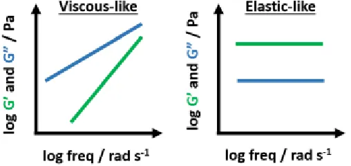
and increase network density. A fully crosslinked sample displays gel-like response, where the moduli are frequency independent, G” << G’, and the elastic modulus plateaus. Idealized plots
of frequency sweep are picture below (Figure 2.5).
Figure 2.5. Two extreme situations in gelation: frequency dependence of a viscous-like fluid (left) is observed prior to gelation (G” > G’), and frequency independence of a fully crosslinked gel (right) where G” < G’.
2.3. Electrospinning
Electrospinning is a fiber synthesis technology dating back to the early 1900s, when
J.F. Cooley [95] and W.J. Morton [96] described formation of polymer fibers by exceeding surface tension with charge. The method remained dormant until its revival nearly a century
later in the 1990s by the Reneker group. [97] Electrospinning produces 1-D polymer fibers, or composite fibers, with diameters on the order of 0.1 to 1-μm. The process is continuous and
ideal for scalability, with applications ranging from medicine to electronics to catalysis.
Electrospinning is a complex process; many process variables (including humidity, electric