509-0162 CANONsama NETWORK VIDEO RECORDER VK-64/VK-16 USER’S MANUAL hyo1-4
Network V
ideo Recorder
VK-64/VK-16 v1.1 User
’s
Manual
User’s Manual
Ver. 1.1
Network Camera Recording and Monitoring System
Network Video Recorder
VK-64/ VK-16 v1.1
Storage Server & Viewer
CANON INC. 30-2, Shimomaruko 3-chome, Ohta-ku, Tokyo 146-8501, Japan
U.S.A. CANON U.S.A.,INC. NEW JERSEY OFFICE
100 Jamesburg Road, Jamesburg, NJ 08831 USA
CANON U.S.A.,INC. CHICAGO OFFICE
100 Park Blvd., Itasca, IL 60143 USA
CANON U.S.A.,INC. LOS ANGELES OFFICE
15955 Alton Parkway, Irvine, CA 92618 USA
CANON U.S.A.,INC. HONOLULU OFFICE
210 Ward Avenue, Suite 200 Honolulu, HI 96814 USA
zIf you have any questions, call the Canon U.S.A. Information Center toll-free at 1-800-828-4040(U.S.A.only)
CANADA CANON CANADA INC.NATIONAL HEADQUARTERS
6390 Dixie Road, Mississauga, Ontario L5T 1P7
CANON CANADA INC. CALGARY
2828, 16th Street, N.E, Calgary, Alberta T2E 7K7
CANON CANADA INC. MONTRÉAL
5990 Côte-de-Liesse, Montréal, Québec H4T 1V7
zIf you have any questions, call the CANON CANADA Customer Information Centre toll-free at 1-800-OK-CANON (652-2666) (Canada only)
MEXICO CANON MEXICANA, S DE R.L.DE C.V.
Boulevard Manuel Avila Camacho, No.138 PB, Pisos 15, 16 y 17 Col Lomas de Chapultepec C.P. 11000 México, D.F. México
CENTRO Y
SURAMERICA CANON LATIN AMERICA, INC.
703 Waterford Way, Suite 400, Miami, FL33126, USA
ASIA CANON SINGAPORE PTE LTD
1 HarbourFront Avenue, #04-01, Keppel Bay Tower Singapore 098632
CANON HONGKONG CO., LTD.
19/F., The Metropolis Tower, 10 Metropolis Drive, Hunghom, Kowloon, Hong Kong
OCEANIA CANON AUSTRALIA PTY. LTD.
1 Thomas Holt Drive, North Ryde, Sydney, N.S.W. 2113, Australia
EUROPE CANON EUROPA N.V.
Bovenkerkerweg 59-61, P.O. Box 2262, 1180 EG Amstelveen, The Netherlands
CANON EUROPE LTD.
6 Roundwood Avenue, Stockley Park, Uxbridge Middlesex, UB11 1JA, United Kingdom
Introduction
2
Thank you for purchasing Network Video Recorder VK-64 v1.1(hereafter referred to as ‘VK-64’), a network video recording and monitoring system.
This manual describes the configuration and operation procedures for Storage Serverand
Viewer. Please read this manual prior to operation to ensure you will be able to use the Viewer and Storage Server effectively. This manual is also intended for Network Video Recorder VK-16 v1.1 (hereinafter referred to as ‘VK-16’). Please refer to page 7 for differences between VK-64 and VK-16. When you have finished reading this manual, please store it in a safe place.
Request to Customers
(1) The content of this manual may not be reproduced in its entirety or in part without prior permission.
(2) The content of this manual is subject to change without notice.
(3) All possible measures have been taken to ensure that the content of this manual is accurate. If you happen to notice errors, omissions or other faults, please contact your vendor.
(4) Irrespective of items (2) and (3) above, Canon cannot bear responsibility for any effects that result from operation.
Trademarks
Canon and the Canon logo are registered trademarks of Canon Inc.
Microsoft Windows is a trademark of Microsoft Corporation in the United States and other countries. QuickTime is a trademark of Apple Computer Inc.
Apache is a trademark of the Apache Software Foundation.
Windows is legally recognized as Microsoft Windows Operating System. Pentium is a trademark of Intel Corporation.
All other company or product names used in this manual are trademarks or registered trademarks of their respective holders.
Copyright Information
Please note that copyright laws prohibit the customer from using recorded videos and still pictures for any purpose other than personal requirements, without permission from the copyright holder.
Support Information
For various types of information relating to support, including updated product software (patch installer), User’s Manual, operating environment, etc., please refer to our WebView Product web page: http://www.canon.com/webview
Icons Used in this Manual
Indicates important information that must be observed or actions that are prohibited during an operation. These notes must be read to prevent possible faults or errors during operation.
Indicates supplementary information or a reference to an operation. Users are advised to read these memos.
Note
Tip
Document No. 3743 Version 1.0, 030904. Storage Server includes software developed by the Apache Software Foundation (www.apache.org). The Apache software is Copyright (c) 2000-2003 The Apache Software Foundation. All rights reserved. For the license terms associated with this software, please refer to the file APACHE_LICENSE in the folder LICENSE, within the installation directory.
VK-16 has the same functionality as VK-64 outlined in this manual, unless explicitly indicated otherwise.
3
Introduction . . . .2
Overview . . . .7
System Configuration . . . .8
Typical System Configuration . . . .8
Overview of Setup . . . .10
Supported Camera Servers . . . .12
Canon Camera Servers . . . .12
Firmware Upgrade . . . .12
Operating Environment . . . .13
Viewer System Requirements . . . .13
Storage Server System Requirements . . . .13
Using the Storage Server with Windows XP SP2 . . . .14
PART 1: INSTALLATION & CONFIGURATION
Chapter 1 Installation
Before you begin installation... . . . .16Suggested Network Configurations . . . .16
Setting up the Camera Servers . . . .18
About the Master Storage Server . . . .18
When using multiple Storage Servers... . . . .18
Installation Procedures . . . .19
Starting up the Installer . . . .19
Upgrading from Version 1.0 . . . .20
Chapter 2 Configuring the Storage Server
Storage Server Configuration . . . .22Launching Procedure . . . .22
Adjusting the Storage Server Settings . . . .22
How the Storage Server manages disk space . . . .24
Setting up Event Notifications . . . .25
Set up a user to receive Event Notification emails . . . .25
Setting up Users . . . .26
Adding and Editing Users . . . .26
User Management tab - Add Users . . . .27
User Management tab - Edit Users . . . .28
User Management tab - Remove Users . . . .28
Chapter 3 Starting the Viewer
Starting the Viewer . . . .30Launching Procedure . . . .30
Changing the Storage Server . . . .31
Setting the Master Storage Server . . . .31
4
Chapter 4 System Configuration, Before You Begin
After the Viewer has launched... . . . .34
Accessing the Configuration and Preferences screen . . . .35
System Configuration Process . . . .36
Configuration and Preferences screen . . . .38
About the Configuration and Preferences screen . . . .38
Selecting a Configuration and Preferences window . . . .38
Chapter 5 Register Storage Servers and Camera Servers
Camera Summary Window . . . .42About the Storage and Camera Server Summary Window . . . .42
Storage Server and Location / Zone options . . . .43
Other functions in both sub-windows . . . .43
Locations and Zones . . . .44
About Locations and Zones . . . .44
Configure Camera Summaries . . . .46
Camera Summary - Add, Edit and Delete a Storage Server . . . .46
Camera Summary - Add, Edit or Delete a Location/Zone . . . .47
Camera Summary - Find Camera Servers . . . .49
Using the Add Camera Server Dialog . . . .51
About the Add Camera Server Dialog . . . .51
Set up camera position and saved video . . . .52
Add a Camera Server - Set connection details . . . .53
Camera Summary - Edit Camera Server Settings . . . .55
Edit and Remove Camera Servers . . . .57
Camera Summary - Edit Camera Server . . . .57
Camera Summary - Remove Camera Server . . . .58
Saving Configuration Changes . . . .59
Camera Summary - When you have finished configuration . . . .59
Chapter 6 Configuring Recording Schedules
Configure Normal Recording . . . .62About the Recording Schedules window - Normal Recording . . . .62
Create, Edit and Delete Recording Schedule Items . . . .64
Add/Edit Schedule Item dialog - Schedule field . . . .66
Add/Edit Schedule Item dialog - Recording Settings field . . . .67
Configure Motion and Sensor Settings . . . .70
Recording Schedule dialog - Motion and Sensor Settings . . . .70
Recording Schedule - Edit Motion Detection Settings . . . .71
About motion detection on different camera servers . . . .75
Recording Schedule - Edit Sensor Events Settings . . . .76
Saving Normal Recording Changes . . . .79
When you have finished Normal Recording configuration... . . . .79
Configure Special Day Recording . . . .80
5
About Special Day Recording . . . .80
Add and Edit a Schedule Type . . . .82
Delete a Schedule Type . . . .83
Add a Day . . . .84
Delete a Day . . . .85
Saving Special Day Changes . . . .86
When you have finished Special Day configuration... . . . .86
Chapter 7 Configuring Viewer Settings
Configure Viewer Settings . . . .88About the Viewer Settings window . . . .88
Viewer Settings window - Use large captions for Video Windows . . . .90
Viewer Settings window - Identify the Master Storage Server . . . .90
Viewer Settings window - Edit Event Notifications . . . .91
Saving Viewer Settings . . . .92
When you have finished configuring Viewer settings... . . . .92
PART 2: USING THE VIEWER APPLICATION
Chapter 8 Using the Viewer - Operator Login
Viewing Screen Example . . . .94Starting the Viewing Screen . . . .96
Launching Procedure . . . .96
Viewing Screen Menu bar . . . .98
Menu Bar Functions . . . .98
Chapter 9 Working with Video Windows
Selecting Cameras for Viewing . . . .100About the Camera Selection Area . . . .100
About Camera Thumbnails . . . .100
Selecting Locations and their Zones . . . .101
Basic Video Window Functions . . . .102
Creating, scaling and moving Video Windows . . . .102
Selecting Multiple Video Windows . . . .105
Video Window States . . . .106
About Video Window states . . . .106
Adjust Pan, Tilt and Zoom . . . .108
Viewing Live Video - Adjusting Pan, Tilt and Zoom . . . .108
Other Video Window Functions . . . .110
Change the size of a Video Window . . . .110
Enable Backlight Compensation . . . .110
User-initiated Recording . . . .111
Other Menu Options . . . .111
Chapter 10 Arranging and Saving Video Window Layouts
Managing Video Layouts . . . .114
About the Layout menu . . . .114
Organizing Layouts and Layout Sequences . . . .115
Saving a Layout or Layout Sequence . . . .117
Arranging Layout Sequences . . . .118
Working with Layout Grids . . . .119
Working with the Alignment Grid . . . .119
Working with Small, Medium and Large Grids . . . .120
Working with the Custom Grid . . . .123
Removing a Layout Grid . . . .123
Hiding and Showing Task Areas . . . .124
Using the View menu to hide and show Task Areas . . . .124
Chapter 11 Using the Timeline and Viewing Events
Using the Timeline . . . .126Timeline Overview . . . .126
Monitoring Live Video in relation to the Timeline . . . .127
Using the Timeline to examine, play and extract video . . . .128
Daylight Savings Indicator . . . .130
Extracting video to save to another location . . . .131
Viewing and Searching Events . . . .132
About Live Events . . . .132
Display the Live Events Log (if not displayed) . . . .133
Overview of Alert Parameters . . . .133
Searching Events . . . .134
Selecting Criteria for Searching . . . .135
Viewing found events . . . .136
Appendix A Troubleshooting VK-64
Troubleshooting VK-64 . . . .138Appendix B Example Operating Conditions
Example Operating Conditions . . . .144Frame sizes . . . .144
Bandwidth and Disk Space . . . .145
Disk Space Management . . . .146
Storage Server Performance . . . .148
VK-64 File Locations . . . .150
Index
Index . . . .151Contents
7
Overview
VK-64 is software that allows you to view and record images transmitted from the Network Camera Server VB150/VB101 and Network Camera VB-C50i/VB-C50iR/ VB-C50FSi/VB-C50Fi/VB-C10/VB-C10R (hereafter referred to as ‘Camera Servers’). The software can support up to 64 cameras via an IP network such as a LAN, or up to 16 cameras for Network Video Recorder VK-16 v1.1.
VK-64 consists of two applications: Storage Serverthat lets you record video from multiple camera servers and save event information (sensor and motion-detection inputs); and Viewerthat lets you view live video from multiple Camera Servers and playback recorded video stored on Storage Servers.
Video resolution can be as high as 640 x 480 pixels, 30 fps for NTSC and 768 x 576 pixels, 25fps for PAL (depending on Camera Servers installed).
The following table shows each product and license number:
The VK-16 Viewer is identical to the VK-64 Viewer.
Storage Server Viewer
VK-64 Up to 64 cameras can be registered
VK-16
Up to 16 cameras can be registered Functionality is the same as for VK-64 except for the above camera limitation.
Common
Product Name Storage Server Viewer
Network Video Recorder VK-64 v1.1 1 license 1 license
Network Video Recorder VK-16 v1.1 1 license 1 license
Network Video Recorder VK-64 v1.1 Viewer License _ 1 license
System Configuration
8
Typical System Configuration
VK-64 provides video viewing and recording from Camera Servers via an IP network such as a LAN. Since VK-64 makes use of IP networks, installations of cameras can be performed easily. In addition, it is possible to flexibly install new cameras and change installation locations of cameras.
VB-C50iR
VC-C50i VC-C50iR VB150/VB101
VB-C50i
MONITOR
MONITOR
View live and recorded video
Viewer
Operator Capabilities:
View Live Video View Events View Recorded Video
PLAYBACK
PL
PLA YBACK
PLA YBACK
9 RECORD
RECORD R
MONITOR
Record video to the Storage Server # 1
Storage Server
Administrator Capabilities:
Configure Users Configure Storage Server Configure Event Notification
Record video to the Storage Server # 2
Storage Server
View live and recorded video
Viewer
Administrator Capabilities:
Configure recording settings Configure event alerts Camera Server Settings Storage Server Settings View Live Video View Events View Recorded Video
View live and recorded video
Viewer
Operator Capabilities:
View Live Video View Events View Recorded Video
Receives and
records video. Plays back recorded video to Viewers.
Application Function
Storage Server Stores recorded information for later retrieval and viewing in the Viewer.
Viewer Lets users view recorded information, monitor live video and acknowledge/search events.
Lets Administrators configure recording and viewing settings.
Application Types and Functions
PLAYBACK CK
PLAYBACK
Overview of Setup
10
Before you can start monitoring, recording and playing back video, you need to install and configure the Storage Server and Viewer. The diagram below indicates the installation and configuration process.
The first step is to set up your cameras and/or Camera Servers. Refer to your camera and Camera Server manuals for connection details.
Set up Network Cameras
1
Camera servers (tP. 12)
VC-C50i
VB150
Install Storage Server and Viewer
2
Install the Storage Server and Viewer on one computer or install the Viewer on other computers on the network that will access recorded video from the Storage Server. Configure the Storage Server via the Storage Server Configuration utility to set server settings, event notification and configure user privileges.
11
Register Camera Servers and Storage Servers and set up recording schedules.
Monitor live video and play back pre-recorded events in the Viewer
application. From here you can customize the Viewing Area and save Layouts.
Configure Recording Settings
3
Create and save Viewer Layouts
4
Pre-recorded video from Storage Server
Supported Camera Servers
12
Canon Camera Servers
The table below lists the Camera Servers that are supported by VK-64.
This information is correct as at September 2005.
For the latest information, please refer to our WebView Product web
page: http://www.canon.com/webview
Camera Server Firmware Versions
VB-C50i VB-C50iR Ver. 1.1 Rev. 33 or later
Ver. 1.0 Rev. 68 or later
Ver. 1.0 Rev. 33 or later
VB-C10 VB-C10R Ver. 1.0 Rev. 26 or later
VB150 Ver. 1.1 Rev. 30 or later
VB101 Ver. 3.0 Rev. 68 or later VB-C50Fi
VB-C50FSi
If using a VB101, you can make use of a single camera connected with VK-64 at a time.
If using a VB150 with multiple cameras, there are restrictions on frame rate. Refer to your VB150 User’s Manual for details.
Note
Firmware Upgrade
Operating Environment
13
This information is correct as at September 2005.
For the latest information, please refer to our WebView Product web
page: http://www.canon.com/webview
Viewer System Requirements
Storage Server System Requirements
Minimum
CPU Pentium 4 2.2GHz or greater
Operating System
Memory 1GB RAM or greater
For more than 16 Camera Servers, 1GB or greater required.
Hard Disk
Display 1024 x 768 with 16 bit color
A high performance video card is desirable. With PCI video cards, display performance may be reduced.
Sound
Minimum
CPU Pentium 4 2.2GHz or greater
Operating System
Windows 2000 Server (with SP4) Windows 2000 Professional (with SP4) Windows XP Professional (with SP2)
Windows Server 2003 Standard Edition (with SP1)
Memory 1GB RAM or greater
For more than 48 Camera Servers, 1.5GB or greater required.
Hard Disk
The requirements for Storage Server will vary according to the environment you will use (number of Camera Servers, setting of recording frame rate etc.). It is also dependent on pre-event recording settings. Please contact dealers that handle Canon products for further information. If using Windows XP Professional SP2, follow the procedures as described on the following page for configuring your Windows firewall settings.
If using Windows XP Professional SP2, follow the procedures as described on the following page for configuring your Windows firewall settings.
Audio playback support is necessary for event notification alert sounds.
20GB HDD or greater, SCSI or IDE, NTFS formatted 2GB HDD or greater
Windows 2000 Server (with SP4) Windows 2000 Professional (with SP4) Windows XP Professional (with SP2)
Operating Environment
14
Before starting operations with VK-64
It is recommended that you perform tests under actual conditions before starting operations.
Recording and display of live videos may not be provided as configured because many factors (such as network environment and PC performance) affect the actual performance of VK-64.
When the load on your computer CPU and hard disk is high, the specified frame rate may not be available, or the video recording may be interrupted or the Viewer operation may take longer. Also, when available disk space is low, the disk load may increase and the video recording may be interrupted due to deletion of the recorded video file (tP.24).
Using anti-virus and firewall software may affect Storage Server and Viewer operations.
When using a proxy server
If you use a proxy server, recording frame rate may not be achieved as specified or live video monitoring may be interrupted. Also, communication between the Storage Server and Viewer may occasionally be disconnected.
When using the Audio feature (VB-C50i, VB-C50iR and VB-C50FSi) The Admin Viewer supports audio transmission and reception. Audio recording is not available.
The audio and video may be out of sync.
Depending on the performance of your PC and network environment, the audio stream may be interrupted.
The audio feature is not available via a proxy server.
If you use a PC on which anti-virus software is installed, the audio stream may be delayed or the audio stream may be temporarily interrupted.
Note
Using the Storage Server with Windows XP SP2
If your Storage Server is not installed on the same PC as your Viewer, you will need to change your Windows firewall settings for the Storage Server on the PC with Windows XP SP2. After installation of the Storage Server on a PC with Windows XP with SP2:
1. From the Windows Start menu, launch the Control Panel.
2. In Control Panel, select Windows Firewall. If Windows Firewall is not shown, select
Security Centerand then select Windows Firewall.
3. In the Windows Firewall dialog, select the Exceptiontab and then click Add Port.... 4. In the Add a Port dialog, enter a name for the Storage Server, e.g., ‘VK-64 Storage
Server’.
Enter the Port number as ‘80’. Make sure the TCPprotocol is selected and click OK. 5. In the Windows Firewall dialog, your Storage Server is now listed. Make sure it is
enabled (checked). Click OKto close the dialog. Settings are now complete.
Chapter
1
Installation
This chapter outlines the installation of the Storage Server and Viewer.
Before you begin installation...
16
Suggested Network Configurations
It is highly recommended that Storage Servers and Viewers be used on private networks.
When Viewing and Recording with one PC
When you Install VK-64, you can select to install both the Storage Server and Viewer software on the same computer.
When Viewing and Recording with Several Viewers
Storage Server (recommend separate hard drive for recorded video).
Storage Server
Viewing Recorded Events and Monitoring
Viewer
Record video to the Storage Server
Storage Server
View live and recorded video Viewer
View live and recorded video Viewer
Receives video and controls camera.
Receives video and records footage.
Install Storage Server and Viewer on one PC and Viewer on several other PCs.
VB-C50i
Server & Viewer
Viewer
Viewer
Having many Viewers accessing the same Camera Servers and Storage Servers will affect system performance.
Installation of both Storage Server and Viewer on a single PC causes a heavy load on your PC. If you use VK-64 with many camera servers or the frame rate for live video is high, install each application on separate PCs.
If the maximum frame rate for live viewing is 10 fps or more, viewing with a low capacity PC may take longer, the specified frame rate may not be achieved, recording frame rate may be lower or recording may be interrupted. Please reduce the live viewing frame rate or use a separate PC.
17
When using multiple Storage Servers and Viewers
Receives video and records it. Receives video and records footage. Plays back recorded video Plays back recorded video
One or more Storage Servers can be used on a network and Viewer applications can be configured to play video from more than one Storage Server. For each Viewer, a Master Storage Server (tP. 18) is defined for saving information such as zones and locations of cameras, as well as saving Viewer layouts created by the user.
Record video to the Storage Server #1
Master Storage Server
Record video to the Storage Server #2
Storage Server
View live and recorded events
Viewer
More than one Storage Server can be added to a network. Viewers can receive playback video from more than one Storage Server.
Receives video and controls camera.
View playback video from Storage Server #1 and #2
View playback video from Storage Server #2 View playback video
from Storage Server #1
You can operate VK-64 with up to three Storage Servers using any combination of ‘VK-64 Storage Server’ and ‘VK-16 Storage Server’. Up to five Viewers can connect to the Storage Servers at the same time. If you wish to install Storage Servers and Viewers on multiple PCs, you’ll need to purchase the necessary licenses separately.
Before you begin Installation...
18
Setting up the Camera Servers
First make sure the firmware is the required version or later (as specified in the table tP. 12).
Check to ensure the Camera Server has been correctly installed and that the initial settings (network settings) have been made. Then connect to the network.
For procedures on installing and setting up Camera Servers and cameras, please see the User’s Manual supplied with the Camera Servers and cameras.
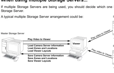
When using multiple Storage Servers...
If multiple Storage Servers are being used, you should decide which one is the Master Storage Server.
A typical multiple Storage Server arrangement could be:
Master Storage Server
Play Video to Viewer
Save Camera Server information Save Zones and Locations Save Viewer Layouts
Play video to V iewer
Play video to V iewer
Storage Server #2
Storage Server #3
Load Camera Server information Load Zones and Locations Load Viewer Layouts
1
2
It is recommended that all Viewers within a system use the same Storage Server as a Master Storage Server. This ensures that all Viewers use the same Zones, Locations and Viewer Layouts.
For correct operation, the time setting of all PCs within a system (including Storage Servers and Viewers) must be correct.
Note
Viewer
About the Master Storage Server
19
Installation Procedures
Starting up the Installer
Insert the Network Video Recorder installation disc into your CD drive. After a moment, the Welcome screen appears. Click Nextto continue.
If the installer does not automatically load, open the CD directory in Explorer and browse to locate Setup.exe. Double-click to begin installation.
The Software License Agreement screen appears. Read the agreement carefully. Click the radio button, I accept the terms in the license agreement and then click the
Next button to continue.
Enter your License Key(s) and click the Next
button. Your License Key is indicated on the ‘About License Key’ included in the package.
1
2
3
1
Inst
allation
Types and number of licenses you can install vary according to the product you have purchased. If additional Storage Server and Viewer installations are required, you will need to purchase the necessary software for each PC.
20
Depending on your License Key, you will be presented with one or both of the following applications shown below:
Viewer
Storage Server
It is recommended to keep the Install To:
path as is. Click the Change... button to choose another installation path if necessary. Click Nextto continue (or view Tip below).
When you click Next, installation will proceed and a progress bar will be displayed.
When the InstallShield Wizard Completed
screen displays, click the Finishbutton.
Installation is now finished.
In future, if you need to check your product type, refer to the ‘About’ box of the Storage Server or Viewer.
4
5
Installation procedures
If the Storage Server is installed, it will be automatically started after installation.
Note
Upgrading from Version 1.0
When installing over an earlier version, VK-64 will attempt to use settings from your previous installation. It is important to verify your settings after installation.
You cannot use v1.1 Viewer with a v1.0 Storage Server, nor can you use a v1.0 Viewer with a v1.1 Storage Server. When installing, make sure you install components that have the same version number.
Note
Click the ‘Help’ button to obtain details on the type of installation. The type is indicated by the icon next to the application to be installed. You can set a custom install here. Click the ‘Space’ button to view the amount of hard disk space required in order to install VK-64. A list of drives is shown. In either dialog, click ‘OK’ to return to the installation steps.
Chapter
2
Configuring the
Storage Server
This chapter shows Administrators how to start and stop the Storage Server if necessary. It also explains how to configure the Camera Server proxy for
Storage Server Configuration
22
Enter a proxy address for connecting to Camera Servers. Enter a name for your Storage Server.
Click the camera icon or right-click the title bar to display the ‘About’ box.
Set Maximum Retained History, Maximum file size / duration and Low disk space threshold.
Set maximum disk space used for each device.
Storage Server status indicator. Storage Server start and stop buttons.
Click Applyto save changes when you modify settings from each tab.
VK-64 can record to any drive that Windows treats as a ‘fixed drive’. Removable drives and network drives are not supported unless the drives are explicitly allowed to be treated by Windows as fixed drives. To check the type of drive, right-click on the drive within Windows Explorer, select ‘Properties’ and note the ‘Type’ displayed.
Note
Adjusting the Storage Server Settings
The Storage Server Configuration dialog, Settingstab allows you to configure:
Storage Server name Proxy for Camera Servers Recording and Drive settings
Launching Procedure
Double-click the Storage Server Configurationdesktop icon. Alternatively, from the Windows Startmenu select:
23
2
Configuring the S
torage Server
If the Storage Server needs to access Camera Servers outside the LAN, you may need to configure proxy settings (see user note tP. 14).
In the Storage Server Proxyfield, tick the
Enable the following proxy serverbox. Enter the Proxy serveraddress and Port.
Enter the Storage Server Proxy Address
1
2
In the Recorded Video Settingsfield, set:
Maximum retained history - Enter a value from 1 to 999 and then select Days
or Weeks from the drop-down menu.
Maximum file size / duration - Select
MB or Hours and enter a value from 1 - 24 for Hoursor 32 - 1024 for MB; for example, ‘100 MB’ or ‘24 Hours’. This will establish the maximum size used for each file of recorded video.
Enter Recorded Video Settings
1
2
3
In the Disk drive settingsfield, set:
Drive - Select the disk drive to configure, from the drop-down menu.
Maximum disk space used- Tick the box and enter a value in Megabytes (MB) or Gigabytes (GB), for example, ‘D: 50 GB’. This establishes the maximum disk space used for all video files on the specified drive.
1
2
Low disk space notification threshold- Enter a percent value. When remaining space reaches, for example, 10%, a notification will be emailed.
Select Disk Drive Settings
If disk space is not enough to cover the specified value configured with ‘Maximum disk space used’, the retained duration of video may be shorter than the specified period or the recording may be temporarily stopped. Please be sure to perform sufficient tests before starting operations.
Note
Start or Stop the Storage Server
You can start or stop the Storage Server using the Start Storage Server/Stop Storage Server
24
Storage Server Configuration
If you need to stop the Storage Server for any reason (such as maintenance) first inform all users connected to the server!
Tip
How the Storage Server manages disk space
This section describes the way in which the Storage Server manages its disk space and determines when old video files should be deleted. It also describes the events and notifications associated with disk usage.
The Storage Server tracks the unused disk space that is currently available for recording video and events for each drive and sets some disk warning and error levels based on this. These levels are used to generate events and alter the behaviour of the Storage Server. For each of the levels, the system can be configured to provide email notifications when one of these levels is reached. The levels it uses are shown in the following table.
The Limit level and the Threshold level are determined by the Storage Server, depending on various conditions and settings. However, an administrator can alter the Low disk level warning value in order to control at what point a Low disk warning is generated.
The warning is triggered when the disk space available for writing goes below the given percentage of the total disk space on the drive. For example, for a 100GB disk and a setting of 10%, the warning would be generated when available space reduces below 10GB. If Maximum Disk Space Used is set, the warning can also be triggered when the disk space available for writing goes below the given percentage of the Maximum Disk Space Used on the drive (if the warning has not already been triggered as above). For example, if the Maximum Disk Space Used is set to 80GB and a setting of 10%, the warning would be generated when the available space reduces to 8GB.
For disk space management operating examples, please refer to page 146.
Level Description Warning / error
Low disk warning level Threshold level Limit level
This is the level of free space at which an early warning will be generated. This allows early intervention by an administrator to avoid problems due to running out of disk space (for example, removing unwanted recording schedules). This is the minimum free space that can be available in order that old video files will be retained. If the free space is ever reduced to this level, the Storage Server starts to delete video files starting at the earliest ones (even if these are within the "Maximum Retained History" value). However if the oldest file is currently used in the Viewer (for example for playback of recorded video), it would not be deleted and the next oldest file will be deleted instead. Deletion will continue until the free space rises above this threshold again.
This is the minimum free space that can be available in order for recording to be continued. If the free space is ever reduced to this level, recording will stop and resume again when the free space rises above this limit again.
Low disk warning Low disk dele-tion
25
Setting up Event Notifications
Set up a user to receive Event Notification emails
The Storage Server Configuration dialog, Events and Event Notificationtabs allow you to set up event priorities and email notification to a particular user.
Example event notification email...
An event of priority 3 occurred on 8/16/2004 at 16:24:08 PM +1000.
Parking Lot 1: Sensor on
Adjust settings for the ‘Events’ tab and ‘Event Notification’ tab...
2
Configuring the S
torage Server
Enter the email subject line, for example, ‘Immediate Action Required’. Enter the address of the recipient and enter your from address. Enable email notification and select a priority. Events of that priority and above will lead to notification emails.
Select a suitable event priority from the drop-down menu for each event type listed.
The priority of an event created by a manual recording using ‘Record Now’ (tP. 111) will always be Priority 1. It cannot be changed from this dialog.
The events associated with ‘Recording engine started’, ‘Data file set’ and ‘User log in’ do not appear in a Viewer’s Timeline, Live Events Log or Event Search Dialog.
Enable authentication (POP-before-SMTP) for connection and enter User Name, Password and POP Server details.
If this is enabled, the Storage Server will attempt to perform a POP login before sending email that may be required for some SMTP servers.
26
Setting up Users
Tick to enable user to have Administrator privileges (full access to configuration functions).
Adding and Editing Users
The Storage Server Configuration dialog, User Managementtab allows you to set up users and their privileges. Administrators have access to the Viewer including Camera Server setup, recording schedules and Viewer setup. Operators only have access to live video and pre-recorded video on Storage Servers they have permission to access.
The User Management tab is laid out in the following manner: Users list - Lists all users who can access the Storage Server.
Add / Edit / Remove- Allows you to add users, edit passwords and remove users.
Use the Addbutton to add users to this field. There is no limit to the number of users you can add.
Click Applyto save changes.
Users who have Operator status cannot configure, register and change Camera Servers, or configure and change recording schedules.
By default, a user ‘admin’ is created with the password ‘NVR’. It is strongly recommended that this is changed after installation. It is necessary to set up users on all Storage Servers. A particular user should be set up to have the same password on each Storage Server.
27
User Management tab - Add Users
The Add Userdialog is used to add new users to the system.
Step 1: Click the Add button
In the User Managementtab, click the
Add button to bring up the Add User
dialog.
Step 2: Enter user details
In the Add User dialog, enter the following details:
Enter the user’s User Name(up to 20 characters).
Create a password for the user (up to 20 characters). The Confirm Password field will become active. Re-enter the password. When you have finished, click
OK. The dialog will close and the user will appear in the user list.
Step 3: Assign user status to Administrator if necessary
In the user list under ‘Administrator’, tick the box to give the new user full access to Network Video Recorder configuration functions, otherwise leave unchanged.
Click Applyto save changes.
1
1
2
2
3
The VK-64 Administrator status is independent of the Windows Administrator status.
Note
2
Configuring the S
28
Setting up Users
User Management tab - Edit Users
The Edit Userdialog is used to edit the password for an existing user. To edit a user:
Step 1: Click to select user, then click the ‘Edit’ button
Click an entry in the user list to select it.
Click the Edit button below the user list to bring up the Edit User
dialog.
Step 2: Change user details
In the Edit User dialog, enter the new password for the user (up to 20 characters). The Confirm Password
field will become active. Re-enter the new password.
Changes are kept when you click OK.
1
2
User Management tab - Remove Users
Click to select user, then click the Remove button
Click a user entry in the user list to select it.
Click the Remove button.
Chapter
3
Starting the
Viewer
Starting the Viewer
30
Click Cancel to setup a different Master Storage Server (discussed on the next page) or wait until the
Logindialog appears.
Enter your User Nameand
Password, and then click the
Login button.
Proceed to Chapter 4. After a moment, the Logindialog appears...
Launching Procedure
Double-click the Viewerdesktop icon.
Alternatively, from the Windows Start menu select:
Programs > WebView Livescope > Network Video Recorder VK Series v1.1 > Viewer.
After launching, the Network Video Recorder VK-64 v1.1start-up screen appears...
The default User Name is: admin
The default Password is: NVR
31
3
S
tarting the V
iewer
In order to retrieve information, you must be connected to a Master Storage Server, even if it is on the same computer as the Viewer.
After installation, the Master Storage Server is set to ‘localhost’. This indicates that the Viewer will attempt to use the local computer as its Master Storage Server.
Note
After installation, the default user ‘admin’ with the password ‘NVR’ is setup. It is strongly recommended that this is changed after installation.
Tip
If you clicked the Cancel button during launch, the Connect to Master Storage Server dialog will appear.
A different Master Storage Server can be selected by overwriting the existing Host Name or IP address and Portnumber with another.
Setting the Master Storage Server
If you are unsure of the address to use, see your System Administrator.
Enter a Storage Server address and Port number
Enter a Host Name or IP
address for a new Master Storage Server, then enter the
Port number.
Click Connect to continue.
1
2
If you installed the Viewer and Storage Server on separate PCs, be sure to configure a Master Storage Server in the first place. By default, the Master Storage Server is set to ‘localhost’.
32
If you need to use a proxy server, set it in the Internet Properties, LAN Settings dialog. To open, select Start > Settings > Control Panel > Internet Options. When the Internet Options dialog opens, select the Connections tab. From here, click the LAN Settings... button to open the LAN Settings dialog. You can adjust your proxy settings from here.
If using a proxy server between a Viewer and a Storage Server, it should be one which does not perform response buffering. Proxies which are configured to perform response buffering may lead to delays in sending small amounts of data (such as events) from the Storage Server to the Viewer. Squid is an example of a proxy which does not perform response buffering, so it is recommended for use between the Viewer and Storage Server. The Apache proxy server does perform response buffering so is not recommended.
Note
The dialog will also be shown when the Storage Server is stopped.
If you want to use the same machine the Viewer is running on as the Master Storage Server, set the Host Name or IP to ‘localhost’ in this dialog.
Tip
Chapter
4
System Configuration,
Before You Begin
When the Viewer accesses a Master Storage Server which has not been set up with camera information, the entire Viewer window is initially blank. You will need to configure the Viewer using the Configuration and Preferenceswindow.
After the Viewer has launched...
34
This chapter is for users with Administrator privileges. Only Administrators can alter Viewer configuration and preferences. If you are a user with Operator privileges, proceed to Chapter 8. Chapter 8 and following chapters explain the various controls and functions in the Viewing Screen.
Note
Configuration settings made by Administrators are not protected from other Administrators making changes to these settings from another Viewer. The last settings made to a Storage Server are the ones that are used. It is recommended that only one Administrator perform configuration on a network at a time.
A configuration process diagram is given on the following pages. Configuration is discussed thereafter. When you have finished configuration, select View > Viewing Screento return to the Viewer.
35
Accessing the Configuration and Preferences screen
To open the Configuration and Preferences screen:
In the Menu Bar, select View > Configuration
The menu bar is located at the top left of the Viewing screen. Select the menu bar item, View > Configuration. The Configuration and Preferences screen opens with the Storage and Camera Server Summary window displayed.
An example configuration is shown below.
4
System Configuration, Before
Y
36
System Configuration Process
After configuring the Storage Server and launching the Viewer, you are now ready to configure the Viewer application for monitoring, recording and playing back video. The flow diagram below shows the Viewer configuration process via the Configuration and PreferencesScreen.
The first step is to register Storage Servers and Camera Servers with the Viewer. You will also need to create Locations and Zones.
These tasks are done in the Camera Summarywindow.
For recording video, set up Normal and Special Day Recording Schedules in the Recording Scheduleswindow.
Register Storage and Camera Servers
1
Set up Recording Schedules
37
Adjust live viewing frame rate, identify an individual Viewer’s Master Storage Server and set priorities for event notifications in the Viewer Settingswindow.
Monitor live camera images and play back pre-recorded events in the Viewer
application. From here you can customize the Viewing Area and save Layouts.
4
System Configuration, Before
Y
ou Begin
Pre-recorded video from Storage Server
Create and Save Viewer Layouts
4
Set up Viewer Settings (optional)
3
Configuration and Preferences screen
38
About the Configuration and Preferences screen
The Configuration and Preferencesscreen is used for configuring one or more Storage Servers and for setting up preferences on a Viewer computer. Storage Servers may include the local computer being used or another computer on the network.
There are three windows in the Configuration and Preferences screen used for connecting and configuring VK-64 settings:
Camera Summary - add a new Camera Server to a zone and search for existing Camera Servers on the network. This is discussed in Chapter 5.
Recording Schedule - set up recording schedules for each known camera and specify events for triggering recording. You can also set special day schedules such as public holidays. This is discussed in Chapter 6.
Viewer Settings - set up event priorities and change the live video frame rate. The current Master Storage Server is indicated. This is discussed in Chapter 7.
Selecting a Configuration and Preferences window
When the Configuration and Preferencesscreen is launched, three tabs are displayed. The default selection is the first tab, the Camera Summarywindow.
39
4
System Configuration, Before
Y
ou Begin
Storage and Camera Summary windows
Recording Schedule
Chapter
5
Register Storage Servers
and Camera Servers
Camera Summary Window
42
About the Storage and Camera Server Summary Window
Click the Camera Summary tab to open the Storage and Camera Server Summarywindow.
The window consists of two sub-windows which are opened by their respective tabs, Storage Servers and
Locations / Zones.
Tree Area Summary Area
Locations / Zonestab selected.
Storage Servers tab selected.
Click and drag scrollbar(s) to view any portions of the Summary Area that are not visible.
tP. 46
43
5
Registering S
torage Servers and Camera Servers
The following options are available via the Storage Serverstab:
Add Storage Server - Allows you to register a Storage Server with the system (up to three is recommended).
Edit - Allows you to change the address of the selected Storage Server.
Select a Storage Server from the tree in the left panel. The right panel will update with a list of Camera Servers recorded by the Storage Server you selected.
Other functions in both sub-windows
Camera server functions are located on the right-hand panel regardless of which tab is selected:
Find Camera Servers - Allows you to initiate a network search for unlisted camera servers on the LAN.
Add Camera Server- Allows you to add a new Camera Server to the system.
Edit Camera Server- Allows you to edit an existing Camera Server’s settings.
Remove Camera Server- Allows you to remove a Camera Server from the system.
Storage Server and Location / Zone options
Click and drag divider line to the right to reveal full values.
The following options are available via the Locations / Zonestab:
Add Location- Allows you to add a new location to the system.
Add Zone - Allows you to add zones to locations.
When you select a zone within a location in the left panel, a list of cameras in that zone is displayed in the right panel.
46
Location #3
Locations and Zones
44
About Locations and Zones
Cameras are grouped into Locations and Zones. Locations could include an office building, shop or school. Zones are sub-categories of Locations, that is, a zone could be assigned to each floor in the office building and specific areas in a shop such as a cash register. A number of cameras can be grouped into one Zone and a number of Zones can be grouped into a Location.
The diagram below illustrates an example of physical Locations and Zones on a VK-64 network which could be the Internet, Local Area Network or both. Viewer access is via the Location and Zone drop-down menus.
Once configured, Locations and Zones are selected from the Viewing Screen Camera Selection area. When you select other locations, their Zones become accessible.
Zones are different areas of the one Location.
Location #2
Zone #4 Zone #5
Zone #6
Zone #8 Zone #7
Location #1 (Shopping Mall)
Zone #1 Zone #2
45
When a Location is selected from the drop-down menu at left, all of the Zones associated with the Location will appear to the right as camera thumbnail images.
This tab containing four thumbnail images indicates that there are four cameras in the Zone.
This tab containing six thumbnail images indicates that there are six cameras in the Zone.
5
Registering S
torage Servers and Camera Servers
The Location/Zone hierarchy is independent of the grouping of cameras into Storage Servers. For example, a single Storage Server may record video from multiple Locations, and cameras from a single Location can be recorded to multiple Storage Servers.
Camera Summary - Add, Edit and Delete a Storage Server
When using multiple Storage Servers, you will need to configure the Storage Servers via the Add Storage Serverdialog shown below.
A Storage Server must first be connected and running on the network as follows:
Click the Add Storage Server button on the Storage Servers tab
In the Camera Summary window, select the Storage Serverstab.
Click the Add Storage Serverbutton. The Add Storage Server dialog opens.
Configure Camera Summaries
46
Enter connection settings and click OK.
Double-click a server in the list; or click to highlight it and click the Edit button. The
Edit Storage Serverdialog appears with the selected server entry displayed. Modify the entry and click OKto close and save changes.
This function lets you change the network address used to access a particular Storage Server in case the address has changed.
The entry for the Master Storage Server cannot be edited or deleted.
Note
1
3
2
1
2
To edit a Storage Server:
It is not recommended to add the same Storage Server more than once (for example, by using Host Name one time and using a corresponding IP address another time).
If you add a Storage Server with a different configuration (such as one managed by another Master Storage Server), your original Locations and Zones will be lost.
47
5
Registering S
torage Servers and Camera Servers
Camera Summary - Add, Edit or Delete a Location/Zone
You can easily add a new location to your system, then add zones to the new location folder. For example, a location could be a supermarket and zones inside that location can include cash register areas, supermarket aisles and entrances.
Step 1: Click the Add Location button on the Locations / Zones tab
In the Camera Summary window, select the Locations / Zones tab if it is not already selected.
Click the Add Locationbutton. The Add Location dialog opens.
Enter the name of the new location (up to 20 characters), then click the OKbutton.
Step 2: Click the Add Zone button on the Locations / Zones tab
In the Camera Summary window, select the Locations / Zones tab if it is not already selected.
Click the Add Zonebutton. The Add Zone dialog opens.
Click a Storage Server in the list to highlight it and select Deletefrom the Edit menu. Alternatively, press the Deletekey on your keyboard.
A confirmation dialog will open. Click Yesto continue or Noto cancel the operation.
A deleted Storage Server is removed from the list and the Master Storage Server no longer recognizes it. If it was running when removed from the list, it will continue to run. It can be re-added to the system with all associations to Camera Servers intact and can also be added to a different Master Storage Server. If this is done, all Location, Zone, thumbnail and Layout information for cameras associated with this Storage Server will be lost.
Note
1
3
2
1
2
1
2
48
Configure Camera Summaries
To edit a Location or Zone:
Double-click a Zone or Location. The respective Edit Zone or Edit Location dialog opens.
Make any changes and click OK to close the dialog.
To delete a Location or Zone:
Click a Zone or Location to select it and select Delete from the Edit menu. Alternatively, click a Zone or Location in the list to select it, then press the Deletekey on your keyboard.
You will be prompted to confirm deletion. Click Yes to continue or Noto cancel the operation.
If you want to add a Zone to another location not listed, you must first create the Location before you add the Zone.
Each Location name must be unique and each Zone name within a Location must be unique.
There is no fixed limit on the number of Zones and Locations that can be added.
Note
1
2
1
2
Enter the name of the new zone (up to 20 characters).
Select a location from the drop-down menu in the Add to Locationfield, then click the OK
button.
The selected zone will now appear in the specified Location folder.
The camera names listed are those specified by the camera server. Please refer to the camera and camera server User's Manual for details on how to specify camera names. ('Camera Name' includes VB-C50i, VB-C50FSi, VB-C50Fi and VB-C10. 'Device Name' includes VB150 and VB101.)
Note
Camera Summary - Find Camera Servers
The VK-64 Network Video Recorder System can be expanded to include more Camera Servers. You can easily locate Camera Servers via the Find Camera Serversbutton.
Step 1: Click the Find Camera Servers button
In the Camera Summary window, click the
Find Camera Servers button which is located above the right-hand panel in both the Storage Servers and Location/Zones window.
The Search Results dialog opens and a list of detected Camera Servers will appear.
49
5
Registering S
torage Servers and Camera Servers
Configure Camera Summaries
When you initiate the Find Camera Servers function, your computer searches the Viewer’s local subnet for all Camera Servers connected to it. It will not find Camera Servers on a different subnet where a Storage Server may be connected for example, nor find Camera Servers on the Internet.
50
Configure Camera Summaries
Step 2: Select a new Camera Server
In the Search Results dialog, click a Camera Server in the search results list to select it. Click the Add Camera Server...button. This will bring up the Add Camera Server
dialog where you can configure settings for the Camera Server.
Alternatively, double-click an item to bring up the Add Camera Server dialog.
Using the Add Camera Server dialog is discussed on the following pages.
You can also launch the Add Camera Server dialog in the following manner:
Click the Add Camera Server button in the Camera Summary window
This will bring up the Add Camera Server
dialog discussed on the following pages.
51
5
Registering S
torage Servers and Camera Servers
For more information on VB150 Video Input settings, please refer to Chapter 3, Detail Settings, in your VB150 User’s Manual.
Note
About the Add Camera Server Dialog
The Add Camera Serverdialog’s appearance will depend on the type of Camera Server connected and the number of cameras that have been set up. Differences are in the way camera selection is presented.
The Add Camera Serverdialog for a VB-C50i/ VB-C50iR/VB-C50FSi/VB-C50Fi/VB-C10/ VB-C10R/VB101 or VB150 with the Video Input set to Single will display a single camera in a single tab.
The Add Camera Serverdialog for VB150 with the Video Input set to Multiple will show one or more cameras as tabs (see Note below). Click a tab to view that camera.
52
Set up camera position and saved video
TheAdd Camera Serverdialog allows you to set a camera thumbnail image for the Viewer and to choose a Storage Server for recorded video.
The dialog shown below illustrates an example VB-C10 setup. It could also represent a VB-C50i, VB-C50iR, VB-C50FSi, VB-C50Fi, VB101 and VB150 with only one camera setup or in a single mode.
Connection Settings
Set the Storage Server for saved video, or select ‘Do not record’.
Select a drive on the Storage Server to save video. One or more inputs may
show. The states for these can be ‘inverted’.
Adjust camera angle Set backlight compensation.
The Viewer does not store its own names for camera servers or sensors. It displays names which are configured and stored on the Camera Server. Please refer to your VB User’s Manual for more details on setting names.
These settings specify information about recording. To initiate recording, refer to Chapter 6 for configuring recording schedules.
Note
You must click the Connect button before clicking OK to close the dialog (the OK button is disabled until you do so).
The number of tabs shown for a VB150 does not indicate the physical number of cameras connected. It indicates the number of cameras which have been enabled using the VB150 Camera and Video Settings Page. Please refer to Chapter 3, page 40 of the VB150 User’s Manual for more details.
For VB101 (or VB150 in ‘single mode’), the camera name displayed is the first camera name in the server’s camera name list. This allows an Administrator to set the first camera name to be a general name, applicable to the entire camera server.
If you are using a VB101 or VB150 with the ‘Settings Web page URL’ other than the default setting ‘admin’, a connection error occurs when you click the Connect button. Restore the default setting and try again.
Note
53
5
Registering S
torage Servers and Camera Servers
Add a Camera Server - Set connection details
To add a Camera Server, you must specify how VK-64 can connect to the camera server as follows:
Step 1: Enter Host Name, User Name and Password
Enter the Host Name or IPaddress, then enter the port number for the Camera Server.
Enter a User Name and Password
for connecting to the Camera Server. Details will be kept on the Storage Server for use in recording.
1
2
Using the Add Camera Server Dialog
This is the User Name and Password configured on the VB Camera Server side, not your VK-64 password. If you do not know your Camera Server user name and password, see your System Administrator.
Note
Step 2: Click the Connect button
Click the Connect button when you have added the above information. Once the Viewer has connected with the Camera Server:
For a VB-C50i/VB-C50iR/VB-C50FSi/VB-C50Fi/VB-C10/VB-C10R and VB101, or VB150 in Single mode, one tab is shown.
54
Using the Add Camera Server Dialog
Step 3: Select the Storage Server for recording
Select a Storage Server from the drop-down menu which lists pre-configured Storage Servers and enter the Host Name or IPaddress and Portnumber.
If you do not wish the camera server to be recorded, select the Do Not Record option from the drop-down menu.
1
2
Setting a value for the Storage Server does not mean that video will be automatically recorded. Please refer to the next chapter for information on setting recording schedules.
There is a maximum number of 64 camera servers that can be registered on one Storage Server with VK-64 (or 16 cameras with Network Video Recorder VK-16 v1.1).
Note
Step 4: Select the input state for the camera server
In the Camera Server Settingsfield, one or more Input boxes may display, depending on the camera server setup. If a sensor input is received, you can swap its value from ‘on’ to ‘off’ (with respect to the operation of schedules) by ticking the
Inputbox. This acts as a ‘toggle’ control.
If you have a Multi-Terminal Module VB-EX50 unit plugged into a VB-C50i/VB-C50iR/VB-C50FSi/VB-C50Fi and have configured the ‘Use External Video Input’, video seen in the Viewer will be taken from cameras connected to the Multi-Terminal unit. Please refer to the camera server User’s Manual.
55
Using the Add Camera Server Dialog
Camera Summary - Edit Camera Server Settings
The right-hand side of the Add Camera Server dialog may show one or more enabled cameras (depending on the type of Camera Server you are using). To edit settings:
Step 1: Select a camera tab if available
VB150: Click a tab to display that camera’s settings.
Step 2: Assign a location and zone
In the Locationfield, select a location for the camera from the drop-down menu.
In the Zonefield, select a zone for the camera from the drop-down menu.
If necessary, click the Add...button to add another Location or Zone. The respective Add Location or Add Zone dialog will appear for you to enter details.
When you have entered details, click the OK button to close the dialog and return to the previous dialog.
When you add a Zone in the Add Zone
dialog, you must also add it to a Location in the same dialog.
Select a location from the drop-down menu.
Adding zones and locations is discussed on previous pages.
5
Registering S
torage Servers and Camera Servers
56
Using the Add Camera Server Dialog
Step 3: Update and setup camera thumbnail for Viewer
In the Previewarea, a camera view is given. Click the Updatebutton to grab a current frame from the camera. It will be re-sized in the preview window and saved for reference as a Viewing Screen camera thumbnail.
If you are not happy with the frame, click the Start Controlbutton. You can then use your mouse to redirect the viewing angle and zoom in or out.
1
2
Move the mouse cursor around the image. Arrows will appear and you can click and drag the cursor in that direction. The preview will change accordingly. When you move the mouse cursor to the center of the image, a zoom in or zoom out control will appear. For a VB-C50FSi and VB-C50Fi, only zoom is available. Hold down the mouse on ‘
+
’ to zoom in.Hold down the mouse on ‘
-
’ to zoom out.Step 4: Select a hard drive for saving video
In the Drive menu, select a hard disk drive on the Storage Server.
When you have finished configuration, click theOKbutton to close the dialog and return to the Camera Summary screen.
If you do not wish to manually control the camera, choose a pre-defined camera position (if already configured) from the Preset Angledrop-down menu.
3
Presets need to be configured in advance. Please refer to the camera server User’s Manual for details on making camera presets.
Tip
If you want to change the thumbnail and the preview area is blank (and the ‘Update’ and ‘Start Control’ buttons are disabled), click the ‘Connect’ button (located in the Connection Settings field).
57
Edit and Remove Camera Servers
5
Registering S
torage Servers and Camera Servers
Camera Summary - Edit Camera Server
The right-hand portion of the Camera Summary window features the Edit Camera Serve