RANGE DETECTION TECHNIQUE FOR
REAL-TIME VIRTUAL HERITAGE
APPLICATION
Mohd Shahrizal Sunar
Abdullah Mohd Zin
Tengku Mohd Tengku Sembok
INTRODUCTION
imulating real world demand real-time and realism of visual
appearance. In most real-time computer graphics applications
such as virtual walkthrough, flight simulator and games, maintaining the interactive frame rate and smoothness of movement is utmost important. This is essential to give a user an immersive experience in which it will move very smooth during the navigation in the virtual world. Realism as defined in Chiu et al. (1994), means how far the image can visualize in the users mental can be the same as real experience in the real world. According to Dzwig (1988), to generate the realistic 3D world, the geometric complexity level of 3D model has to be increased and this has been agreed by Ramasubramanian (1999). The need for beautiful textures will simultaneously increase the memory usage (Airey 1990).
Angelidis (2001) claimed that there is a trade-off between realism and real-time and also between visual quality and rendering performance. Increasing realism will reduce the processing speed. Therefore, when speed is more crucial, we may have to sacrifice realism to some level. Most of virtual reality applications need more real-time than realism. This is because lots of interactions by user are needed to navigate the application. But,
as agreed by Luebke (2001), realism still can be achieved without sacrificing too many realism needs.
This chapter will discuss about the techniques for optimization in computer graphics and why these optimization techniques are needed. Visibility culling is one of the method that can decrease the high computational of real-time computer graphics applications. As defined in Moller (2002), view frustum culling (VFC) is the simplest visibility culling among the other methods i.e. back faces culling (Zhang 1997) and occlusion culling (Bartz 1999; Aila 2005; Zhang 1998). Only the objects which are inside the frustum will be displayed. This chapter is focusing on the construction of alternative view frustum algorithm for effective rendering and examining a new improvement on view frustum culling approach by Placeres (2005). The approach is defined as a range detection approach which effectively eliminates the unseen objects in the virtual environment.
RELATED WORKS
Visibility is a wide research topic area in computer graphics. It has been studied since early era of computer graphics. The original idea on how to make an efficient view frustum culling was invent by Clark (1976) who used hierarchical approach for visible surface. When the area of computer graphics becomes more popular in 1990's, the algorithms also start growing (Cohen 2003). We focus here on the evolution of view frustum culling techniques.
View frustum culling algorithm can be divided into two common approaches. The first approach is to transform the bounding volume into perspective view. The testing is performed with perspective coordinate system, as initiated in Bishop (1998). Second approach is by checking the bounding volume against view frustum volume represented by its six clipping planes according to Hoff (1999) as agreed with Greene (1994).
The advantage of this approach can make the trivial acceptance and rejection. Then, the test recursively continued based on intersection between a box and a frustum. Greene (1998) showed how to detect the intersection of a rectangular and a convex polyhedron. They also introduced the fast intersection method between polygon and cube. A view frustum culling using probabilistic caching scheme was developed by Slater (1997). The algorithm is implemented using Binary Space Partition tree. Statistical probability representation is used to get faster result than the hierarchical bounding box scheme. The method produced unacceptable errors in some cases.
Bittner (1998) has improved the view frustum culling based on traversal coherency of the scene hierarchy. Certain interior node of the hierarchy is avoided during the intersection test. This technique is not doing the test to the object that is expected to remain visible.
in which both algorithms try to minimize the work by caching information and avoiding more expensive intersection tests.
The view frustum cullling algorithms were improved by Placeres (2005) who used slightly different way of defining the view frustum volume. In this approach, the view frustum volume is identified based on camera referential point and properties.
ANALYSIS OF VIEW FRUSTUM CULLING TECHNIQUE
View frustum can be illustrated as a truncated pyramid representing user's scope of visible view. Essentially it is the field of view of the virtual camera which determines the region of virtual environment that may appear on the screen during run-time. A view frustum is defined by six planes:
(1)
i = 0...5, where ni is the normal and diis the offset of plane πi, and x is an arbitrary point on the plane. We say that a point x is outside a plane πi if . . If the point is inside all planes then the point is inside the view frustum.
To generate a view frustum, a pyramid with surfaces is used. There are two surfaces that represent the nearest and furthers viewpoint. The nearest and furthers representing the boundary of visible objects. Another four surfaces are representing top, bottom, left and right boundary. View frustum in our case is always set in the perspective view mode.
visualization such as medical and military simulation for its efficient rendering.
Each frustum plane is tested if the object is inside or outside the view frustum. Only primitives that are totally or partially inside the view frustum need to be rendered. Three possible output states for bounding box and view frustum test are:
OUTSIDE: All eight points representing the bounding box are totally outside the view frustum. So the object is eliminated from the further processing.
INSIDE: All eight points representing the bounding box are totally inside the view frustum. So there is no further culling calculation. The object is included for the further processing. This state is useful for the application to avoid unnecessary computation.
INTERSECT: Any point of bounding box is inside the view frustum. So down traverse the hierarchy is required. Partial of object geometry is included for the further processing. This state will employ expensive cost of computation. For speed up reason, we consider this state as INSIDE.
RANGE DETECTION TECHNIQUES
Conventional view frustum culling test discussed in previous section was based on the idea that the volume of view frustum is surrounded by six planes. The test is performed against every single plane to detect the bordered objects for viewing using plane equation. Each object is compared six times in each frame to resolve the visibility.
test is done to all point in the virtual environment. The improved approach is based on the formula given in (2).
(1)
n(Ej) = number of objects in group j which is the number of object
we sent to the frame buffer; N = total of objects in the virtual walkthrough application; j = index of group; i = counter number of object in N but not in group j; m = number of N but not in group
j; jc = complement of j. This section will describe the advantage of this approach, which named as Range Detection Technique (RDT).
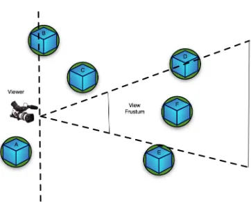
Figure 1.1 Six objects in virtual environment that bounded by sphere and AABB
village houses and trees in the scene is bounded by sphere and AABB. Bounding sphere is generated based on center points and radius of each object in the application. To generate an AABB, the minimum and maximum point information for each object is needed. Then, based on the minimum and maximum point, a box with another six remaining points is generated. Therefore, for each object, eight points defining the AABB is tested to the range of the camera visible boundary. In the front object test, only object A is eliminated. After the sphere test is done using RDT, objects D, E and F are to be saved in the frame buffer. Only objects D and F are to be displayed as output when the AABB test is finished.
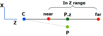
Figure 1.2 The range for point P in z coordinate
(3)
(4)
If the z-coordinate is between the range of near and far then P is possibly inside the view frustum. Then, the x- and y-coordinates must be tested. Otherwise, P is absolutely out of the view frustum.
(5)
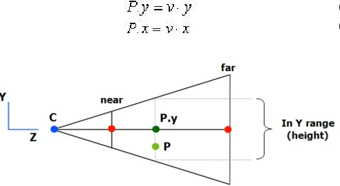
To find x- and y-coordinate of P in camera orientation coordinate, the similar procedure is followed.
(6) (7)
Figure 1.3 Check the y coordinates of P
Figure 1.4 P.y will be compared to the height to test whether it is in view frustum range or not
In order to get the height range of view frustum, the following trigonometry formula is used:
(8)
P is in the view frustum range if P.y value is larger than -h/2 and smaller than h/2.
(9)
Then, we will test the x-coordinate of P easily by checking P.x range of view frustum width. Width, w is computed based on the height and aspect ratio. Aspect ratio is the number of pixels horizontal divided by the number of pixels that can be displayed by the system.
RESULT
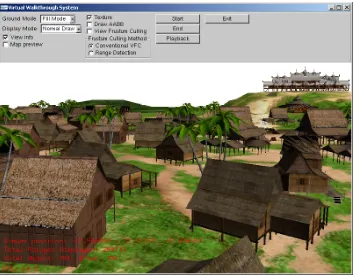
This section describes the implementation and testing results of both normal six planes of VFC, Placeres’s and RDT in Ancient Malacca Virtual Walkthrough project.
Development of virtual heritage environment is built using C++, OpenGL, GLVU and GLUI. The 3D objects of Ancient Malacca are modeled by 3D Studio Max, which is modified from previous project that run at SGI Onyx machine. Intel Pentium 4 3.2 GHz with 512MB RAM and nVidia GeForce FX5950 graphics display card are exploited to test the VFC in virtual walkthrough application.
For testing purpose, it is essential to fix the camera movement path in virtual environment. This is important to ensure the camera to follows the same path for every testing with different culling method.
Figure 1.5 Difference of virtual walkthrough executed between with (bottom) and without (top) RDT
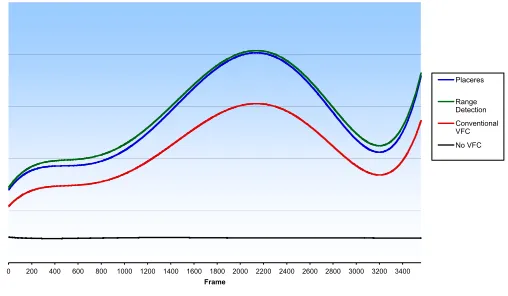
Figure 1.7 Results of frame per second for each normal
conventional VFC, Placeres (2005), RDT and without VFC
The frame per second test is done to the Ancient Malacca virtual walkthrough. The purpose of the test is to measure the performance and the interactivity of the virtual walkthrough system with and without RDT. Besides that, it also shows the difference of smoothness during application run-time with RDT. Figure 1.7 shows the result of frame per second test. The frame rates become higher when the camera reaches to the area with not many objects to be rendered. When, the camera arrived at the area with crowd of objects, the low frame rates obtained. The result shows that the RDT give the highest frame rates among others during the run-time test (Figure 1.8). Without VFC, the frame rates remain 23 and 24 frames per seconds, which is under the expectation of real-time rendering standard.
0 200 400 600 800 1000 1200 1400 1600 1800 2000 2200 2400 2600 2800 3000 3200 3400
Frame
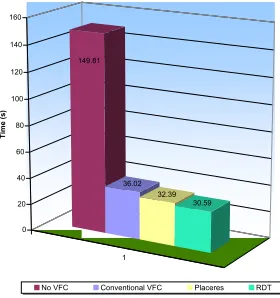
Figure 1.8 An advantage of RDT is the time taken to finish one round of the testing path is shorter than normal VFC
There are five times testing procedures for each approach including with no view frustum culling. Then, it takes the average of the result as shown in the bar chart. As a result, the RDT is the fastest among others.
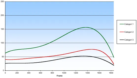
RDT was also tested with different categories of computer system. Figure 1.9 shows the results of frame per second (fps) for RDT running on different specification of computer systems. Category 1 is the highest specification which can run the virtual heritage application in highest fps. This result also shows that RDT can improve the application speed although it was running on the lower specification like in category 3. The specification categories of computer systems used for testing in this research are as follow:
Category 1:
Intel Pentium 4 3.2 GHz (HT), 2046 MB RAM, nVidia GeForce FX5950U with 256MB VRAM.
1 149.81
36.02 32.39
30.59
0 20 40 60 80 100 120 140 160
Ti
me
(s
)
Category 2:
Intel Pentium 4 3.0 GHz, 1024 MB RAM, nVidia GeForce FX5200 with 128MB VRAM.
Category 3:
Intel Pentium 4 1.9 GHz, 512 MB RAM, ATI Radeon 7500 VRAM.
Figure 1.9 The results of frame per second for RDT running on different system category
REFERENCES
Ahmad A. S., 1979,“Sulatus Sulatin (Sejarah Melayu)”. Dewan Bahasa dan Pustaka.
Aila T., 2005, “Efficient algorithms for occlusion culling and shadows”, Ph.D.dissertation, Helsinki University of Technology, Helsinki, Finland, Feb.
0 50 100 150 200 250
0 200 400 600 800 1000 1200 1400 1600 1800
Frame
Categori 1
Airey J. M., Rohlf J. H., and Brooks F. P., 1990, “Towards image realism with interactive update rates in complex virtual building environments”, vol. 24, no. 2, Mar, pp. 41–50. Angelidis A. and Fouquier G., 2001, “Visualization issues in
virtual environments: from computer graphics techniques to intentional visualization,” in WSCG’2001, pp. 90–98. Assarsson U.,2001 “View Frustum Culling and Animated Ray
Tracing: Improvements and Methodological
Considerations”. Tesis Ph.D. Chalmers University of Technology, Goteborg, Sweeden.
Assarsson U. and Möller T., 1999 “Optimized view frustum culling algorithms,” Chalmers University of Technology, Tech. Rep. 99-3, March.
Bartz D., Meißner M., and H¨uttner T., 1999, “OpenGL-assisted occlusion culling for large polygonal models”, Computers and Graphics, vol. 23, no. 5, pp. 667–679.
Bittner J., Havran V., and Slavik P., 1998, “Hierarchical visibility culling with occlusion trees”. Proc. of Computer Graphics International, Jun, pp. 207–219.
Bishop L., Eberly D., Whitted T., Finch M., and Shantz M., 1998, “Designing a pc game engine,” Computer Graphics in Entertainment, pp. 46–53.
Chiu K. and Shirley P., 1994 “Rendering, complexity, and perception,” in Proceedings of the 5th Eurographics Rendering Workshop, Darmstadt, June ,pp. 19–34. Clark J. H., 1976, “Hierarchical geometric models for visible
surface algorithms,” Communications of the ACM, vol. 19, no. 10, pp. 547–554.
Cohen-Or D., Chrysanthou Y., Silva C., and Durand F., 2003, “A survey of visibility for walkthrough applications,” Course 30, SIGGRAPH Course Notes,
Greene N., 1994, “Detecting intersection of a rectangular solid and a convex polyhedron”. San Diego, CA, USA: Academic Press Professional, Inc., pp. 74–82.
Hoff K. E.,1996 “A ”fast” method for culling of oriented bounding boxes (obbs) against a perspective viewing frustum in large “walkthrough” models,” May 1996. [Online]. Available: <http://www.cs.unc.edu/
hoff/research/vfculler/viewcull.html>
Luebke D. P., 2001 “A developer’s survey of polygonal simplification algorithms,” IEEE Computer Graphics Application, vol. 21, no. 3, pp. 24–35.
Moller T. and Haines E., 2002, Real-Time Rendering. Natick, MA, USA: A.K. Peters, Ltd.
Placeres F. P.,2005 “Improved frustum culling,” in Game Programming Gems 5, K. Pallister, Ed. Charles River Media.
Ramasubramanian M., Pattanaik S. N., and Greenberg D. P., 1999 “A perceptually based physical error metric for realistic image synthesis” in SIGGRAPH ’99: Proceedings of the 26th annual conference on Computer graphics and interactive techniques. New York, NY, USA: ACM Press/Addison-Wesley Publishing Co., pp. 73–82.
Slater M. and Chrysanthou Y., 1997. “View volume culling using a probabilistic caching scheme”, in VRST ’97: Proceedings of the ACM Symposium on Virtual Reality Software and Technology.
Placeres F. P.,2005. “Improved frustum culling”. In Pallister, K. (Ed.). Game Programming Gems 5, pp. 65-77.
Masssachusetts: Charles River Media.
Zhang H., 1998. “Effective occlusion culling for the interactive display of arbitrary models”. Ph.D. dissertation, University of North Carolina, Chapel Hill.