Transactions of the 17th International Conference on Structural Mechanics in Reactor Technology (SMiRT 17) Prague, Czech Republic, August 17 –22, 2003
Paper # K12-7
AN EVALUATION OF TENSILE CAPACITY OF CAST-IN-PLACE ANCHOR
WITH CRACK BY ACTUAL MODEL TEST
Jung-Bum, Jang1) , Yong-Pyo, Suh1),and Jong-Rim, Lee1)
1) Korea Electric Power Research Institute, KEPCO, Korea
ABSTRACT
Actual model tests are carried out to develop the model that can accurately incorporate the effect of the various types of cracks in this study. These tests are intended for the cast-in-place anchor that is widely used for the fastening of equipment in Korean NPPs. 115 test specimens with cast-in-place single anchor that is installed in cracked and plain concrete test specimen, are constructed on a basis of ASTM E488 for these actual model tests. As principal test variables, the crack width, the crack depth, and the distance between crack and anchor are chosen. In order to apply the tensile force, 100 tonf-capacity actuator is used with displacement control of 0.5 mm/min. Through these test results, the model incorporating the effect of various types of cracks accurately, is developed and will be available for the anchorage capacity evaluation of equipment for seismic qualification.
KEY WORDS: Cast-in-place anchor, actual model test, concrete breakout strength, crack, ACI 349, CEB-FIP code CCD, SQUG GIP, ASTM E488, seismic qualification, anchorage capacity evaluation, Periodic Safety Review ( PSR )
1. Introduction
The seismic qualification of equipment for the operating Nuclear Power Plants ( NPPs ) in Korea is being carried out as a part of Periodic Safety Review ( PSR ). The anchorage capacity evaluation is the most important for the seismic qualification of equipment. ACI 349, Concrete Capacity Design ( CCD ) procedure, and Generic Implementation Procedure ( GIP ) developed by Seismic Qualification Utility Group ( SQUG ), are available for the anchorage capacity evaluation. But, in case where cracks actually occur at the concrete member of anchorage, it is very difficult to reflect the effect of crack to the anchorage capacity accurately. This is because ACI 349 and CCD procedure adopt the only modification factor according to the existence of crack. GIP also simply adopts the reduction factor according to the crack width. Even though the crack has a large influence on the anchorage capacity, the main reason why those procedures can’t accurately take into account the effect of crack, is the shortage of test data. Therefore, considering that various types of cracks mostly occur at the concrete member of anchorage, it is essential to develop the model to evaluate the anchorage capacity accurately through the sufficient test data.
In order to develop the model incorporating the effect of the various types of cracks accurately and then apply to the anchorage capacity evaluation of equipment for seismic qualification, 115 actual model tests are carried out. These actual model tests are carried out for the anchorage capacity evaluation of Cast-In-Place ( CIP ) anchor in cracked and plain concrete as second stage of overall test plan and tests related to the anchorage capacity evaluation in uncracked and plain concrete were carried out as first stage
2. Design Criteria for CIP Anchor
2.1 ACI 349
The nominal concrete breakout strength
N
cb of a single anchor in tension shall not exceed :b
No N
cb
N
A
A
is the projected area of the failure surface for the anchor that shall be approximated as the base of the
rectilinear geometrical figure that results from projecting the failure surface outward
1
from the centerlines ofthe anchor, or in the case of a group of anchors, from a line through a row of adjacent anchors. shall not exceed
, where is the number of tensioned anchors in the group. is the projected area of the failure surface of a
single anchor remote from edges.
N
A
No
ef
h
5
.
N
A
nA
n
A
No
A
No=
9
h
ef2 ( 2 )The basic concrete breakout strength
N
b of a single anchor in tension in cracked concrete shall not exceed :
N
b=
k
f
ch
ef1.5 ( 3 )where
k
=
24
for CIP anchor
f
c = Compressive strength of concreteh
ef = Effective anchor embedment depthThe modification factor for eccentrically loaded anchor groups,
ψ
1 and edge effects,ψ
2 don’t be considered inthis study.
When an anchor is located in a region of a concrete member where analysis indicates no cracking
(
f
t<
f
r)
under the load combinations with load factors taken as unity, the following modification factor shall be permitted
ψ
3=
1
.
25
for cast-in-place anchors ( 4 )When analysis indicates cracking under the load combinations with load factors taken as unity,
ψ
3 shall be takenas 1.0 for CIP anchors.
2.2 CCD Method of CEB-FIP Code
The nominal concrete breakout strength
N
cb of a single anchor in tension shall not exceed :
N
cb=
ψ
A,Nψ
s,Nψ
ec,Nψ
re,Nψ
ucr,NN
b ( 5 )The basic concrete breakout strength of a single anchor without edge and spacing effects in tension in
cracked concrete shall not exceed :
b
N
N
b=
k
1f
ch
1ef.5 ( 6 )where
k
1=
7
.
5
for CIP anchors.Where,
A
co,N = Area of concrete cone of an individual anchor with a large spacing and edge distance at the concretesurface, idealizing the concrete cone as a pyramid with a height equal to
h
ef and base lengths equal to3
.
0
h
ef2
=
9
h
ef
A
c,N = Actual area of concrete cone of the anchorage at the concrete surface. It is limited by overlappingconcrete cones of adjacent anchors as well as by edges of the concrete member.
The modification factor for eccentrically loaded anchor groups,
ψ
ec,N , for edge effects,ψ
s,N , and forreinforcement with a small spacing,
ψ
re,N don’t be considered in this study.The factor
ψ
ucr,N takes into account whether the anchorage is in cracked or non-cracked concrete.
ψ
ucr,N=
1
.
0
for anchorages in cracked concrete ( 7a )
ψ
ucr,N=
1
.
4
for anchorages in non-cracked concrete ( 7b )2.3 SQUG GIP
If there are significant structural cracks in the concrete where the CIP anchor is installed, then a pullout capacity
reduction factor should be multiplied by the nominal pullout capacity to obtain the allowable pullout
capacity as follows.
)
(
R
cp(
P
nom)
)
(
P
allThe pullout capacity reduction factor applies only to significant structural cracks which penetrate the concrete mass
and pass through the vicinity of the anchor installation. Concrete with surface cracks or shrinkage cracks which only
affect the surface of the concrete should be considered uncracked. It may be necessary to exercise judgment to
establish whether cracks in the vicinity of an anchor actually pass through the installation. Inspections for crack width
should be visual without detailed measurement.
P
all=
P
nomRC
p ( 8 )where,
RC
p = Pullout capacity reduction factor for CIP anchors in cracked concrete= 1.0 for no cracks and for CS p0.01in.
= 1.08−8CS for
0
.
01
in
.
≤
CS
≤
0
.
06
in
.
= Outlier for CSf0.06in.
CS
= Crack size based on visual observation3. Tensile Capacity Evaluation Tests
The objective of this study is to develop the model incorporating the effect of the various types of cracks accurately
through actual model tests and then apply to the anchorage capacity evaluation of equipment for seismic qualification.
These tests are intended for the CIP anchor that is widely used for the fastening of equipment in Korean NPPs. 115
test specimens with CIP single anchor that is installed in cracked and plain concrete test specimen without edge effect,
are manufactured on a basis of ASTM E488 for these actual model tests. As test variables related to the crack, crack
width, crack depth, the distance between crack and anchor, and crack pattern are chosen. In order to apply the tensile
3.1 Test Variables
In order to develop the model that can accurately incorporate the effect of the various types of cracks through actual model tests, typical 2 test variables are considered under concrete cone failure. That is, these test variables are anchor diameter and crack. Test variables related to the crack are divided into crack width, crack depth, distance between crack and anchor, and crack pattern. As mentioned above, edge and spacing effect don’t be considered. The detailed descriptions of principally adopted test variables are as follows.
[1] Load condition
Anchor as fastening system is generally designed by tensile and shear load but in most cases, tensile load is more important than shear load at anchor design. Therefore, only tensile load is taken into account and in order to apply the tensile load to test specimen, 100 tonf-capacity actuator is used and tensile load is gradually increased by displacement control with 0.5 mm/min.
[2] Anchor diameter
Anchor diameters are selected so that concrete cone failure is occurred without steel failure at all tests and in order to identify the influence of concrete breakout strength due to variation of anchor diameters under the same cracked condition, 3 anchor diameters are employed. The selected anchor diameters are 0.75, 1, and 1.25 in. with ASTM A193 Gr B7.
[3] Crack
Test variables related to crack are divided into 4 variable in order to take into account the diverse crack patterns which will be occurred at anchor in NPP. First, crack widths are 0.3, 0.8, and 1.5 mm. Second, crack depths are 1 cm from surface like surface crack, 5 cm as half of effective anchor embedment depth, and 10 cm as full of effective anchor embedment depth. Third, distances between crack and anchor are 0.0 cm like crack passing through the anchor and 7.5 cm as half of ef. Fourth, test cases that 2 cracks are crossed at anchor and occurred oppositely at 7.5 cm as distance between crack and anchor, are considered.
h 5 . 1
As the other test variables, the effective anchor embedment depth is 10 cm and compressive strength of concrete is 280 kgf/cm2 . Table 1 is shown all test cases carried out in this study.
3.2 Test Specimens
According to ASTM E488-96, test specimens should be manufactured so that the minimum clearances between
supports of test specimens are equal to or greater than 4.0 . Also, the test specimens are at least 2.0 in
thickness so long as the depth is suitable for normal installation of the anchor and does not result in premature failure of
either the structural member or anchor. Therefore the minimum clearances between supports of test specimens are
equal to 8.0 and the thickness of test specimens is 4.0
h
in this study. The dimension of test specimen is 1.0 x 1.0 x 0.4 m ( W x L x T ) as shown in Fig. 1. 5 tests per test number of Table 1 are carried out and 5 test results areaveraged for determining the concrete breakout strength of anchor.
ef
h
h
efef
h
efFig. 2 is shown the view which actual model test is being carried out with 100 tonf-capacity actuator.
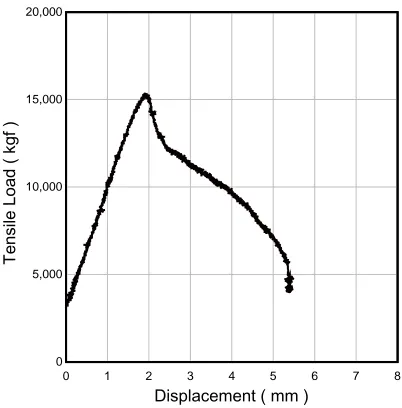
3.3 Test Results
As a result of actual model tests with 115 CIP anchors, all test results are shown the concrete breakout failure, predicted in this study as shown in Fig. 3 and 4.
Table 1. Test cases
Crack Test
No.
Anchor Diameter
( in. )
Width (mm)
Depth (cm)
Distance to anchor (cm)
Crack pattern (No. of crack )
No. of test
1 NA NA NA NA
2 0 1
3 1 7.5 1
4 0 1
5 5 7.5 1
6 0 1
7 7.5 1
8 0 2 ( + )
9
0.3
10
7.5 2 ( = )
10 0 1
11 1 7.5 1
12 0 1
13 5 7.5 1
14 0 1
15
0.8
10
7.5 1
16 0 1
17 1 7.5 1
18 0 1
19 5 7.5 1
20 0 1
21 1.0
1.5
10
7.5 1
22 0.75 1
23 1.25 0.3 10 0 1
5
Summation 115
Displacement ( mm )
Te
ns
ile
L
oa
d
( k
gf
)
0 1 2 3 4 5 6 7 8
0 5,000 10,000 15,000 20,000
Fig. 3 Concrete cone failure Fig. 4 Load – displacement curve
0 1 2 3 4 5
0 2 4 6 8 10 12 14
Tens
il
e L
oad (
tonf
)
Displacement (mm)
0 1 2 3 4 5
0 2 4 6 8 10 12 14
Te
si
le
Lo
ad
(
to
n
f)
Displacement (mm)
( a ) Non-crack ( b ) Crack
Fig. 5 Load – displacement curve
due to the existing crack.
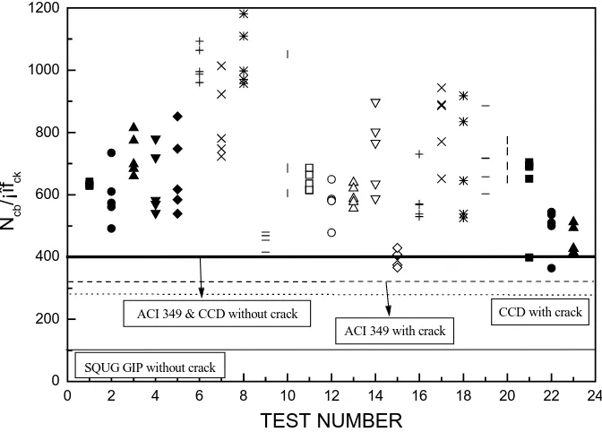
Maximum concrete breakout strength of non-cracked anchor are shown much smaller COV ( Coefficient of Variation ) than cracked anchor and on the basis of minimum concrete breakout strength for each cases, cracked test result are maximum 39 % smaller than non-cracked test result. Maximum concrete breakout strengths of all test cases give a larger than those by three design criteria as shown in Fig. 6. Therefore, design criteria are necessary to modify in accordance with test results.
Surface crack ( less than 1 cm in depth ) doesn’t have an influence on the concrete breakout strength and the side crack ( 0 < distance between anchor and crack < ef ) has an larger influence than the central crack. That reason is because the side crack reduces the failure area which is directly related to the concrete breakout strength. But the central crack has a little influence on the concrete breakout strength due to square plate which is installed at the low part of anchor because even though crack passes through the anchor square plate keeps a concrete failure shape. Therefore, distance between anchor and crack and crack depth are more important than crack width which is being considered at SQUG GIP.
0 2 4 6 8 10 12 14 16 18 20 22 24 0
200 400 600 800 1000 1200
SQUG GIP without crack
CCD with crack ACI 349 with crack
ACI 349 & CCD without crack
Ncb
/¡
îfck
TEST NUMBER
Fig. 6 Test results
Variation of anchor diameters has an influence on the concrete breakout strength as shown in Fig. 6 but it is difficult to come to any conclusion due to deficiency of data. Therefore, tests related to this subject will be carried out after this.
4. Conclusions
In order to develop the model incorporating the effect of the various types of cracks accurately and then apply to the anchorage capacity evaluation of equipment for seismic qualification, 115 actual model tests are carried out. These actual model tests are carried out for the anchorage capacity evaluation of CIP anchor in cracked and plain concrete as second stage of overall test plan and tests related to the anchorage capacity evaluation in uncracked and plain concrete were carried out as first stage.
As a result, cracked anchor is expected that concrete brittle failure behavior will be progressed fastly than non-cracked anchor and on the basis of minimum concrete breakout strength, concrete breakout strength of non-cracked anchor is maximum 39 % smaller than non-cracked. But even though crack is occurred at anchor, concrete breakout strength s of cracked anchor give a larger than those by three design criteria. Also, surface crack doesn’t have an influence on the concrete breakout strength and the side crack has a larger influence than the central crack.
Therefore, distance between anchor and crack and crack depth are more important than crack width which is being considered at design criteria and design criteria are necessary to modify in accordance with test results.
This study will be available for the anchorage capacity evaluation of equipment for seismic qualification at PSR and after all, seismic margin of equipments will be improved in operating NPPs.
References
[1] ACI 349, Code Requirements for Nuclear-Safety-Related Concrete Structures, 2001.
[2] R.E. Klingner, H. Muratli, and M. Shirvani, A Technical Basis for Revision to Anchorage Criteria, NUREG/CR-5563, 1999.
[3] CEB Task Group, Fastenings to Concrete and Masonry Structures, State of the art report, 1994. [4] CEB Task Group, Design of Fastenings in Concrete, Design guide, 1996.