Part No. 060211-10, Rev. F December 2007
The specifications described in this guide are subject to change without notice.
Copyright © 2007 by Alcatel-Lucent. All rights reserved. This document may not be reproduced in whole or in part without the express written permission of Alcatel-Lucent.
Alcatel-Lucent® and the Alcatel-Lucent logo are registered trademarks of Alcatel-Lucent. Xylan®, OmniSwitch®, OmniStack®, and Alcatel-Lucent OmniVista® are registered trademarks of Alcatel-Lucent.
OmniAccess™, Omni Switch/Router™, PolicyView™, RouterView™, SwitchManager™, VoiceView™, WebView™, X-Cell™, X-Vision™, and the Xylan logo are trademarks of Alcatel-Lucent.
This OmniSwitch product contains components which may be covered by one or more of the following U.S. Patents:
•U.S. Patent No. 6,339,830 •U.S. Patent No. 6,070,243 •U.S. Patent No. 6,061,368 •U.S. Patent No. 5,394,402 •U.S. Patent No. 6,047,024 •U.S. Patent No. 6,314,106 •U.S. Patent No. 6,542,507 •U.S. Patent No. 6,874,090
26801 West Agoura Road Calabasas, CA 91301 (818) 880-3500 FAX (818) 880-3505
[email protected] US Customer Support—(800) 995-2696 International Customer Support—(818) 878-4507
Contents
About This Guide ... ix
Supported Platforms ... ix
Who Should Read this Manual? ... ix
When Should I Read this Manual? ... x
What is in this Manual? ... x
What is Not in this Manual? ... x
How is the Information Organized? ... xi
Documentation Roadmap ... xi
Related Documentation ...xiii
User Manual CD ... xiv
Technical Support ... xiv
Chapter 1 OmniSwitch 9000 Series ...1-1 Application Example ...1-2 Availability Features ...1-3 Hardware Redundancy ...1-3 Smart Continuous Switching ...1-4 Software Rollback ...1-4 Hot Swapping ...1-5 Hardware Monitoring ...1-5 Power Checking Sequence ...1-6
Monitoring Chassis Power ...2-21 Checking Chassis Power Before Adding a Module ...2-21 Example 1: Adequate Power to Add a Module ...2-22 Example 2: Inadequate Power to Add a Module ...2-23 Checking Chassis Power Before Shutting Off or Removing a Power Supply ...2-25 Example 1: Adequate Power to Remove a Power Supply ...2-25 Example 2: Inadequate Power to Remove a Power Supply ...2-26 Adding a Power Supply ...2-26 Hot Swapping a Power Supply ...2-26 Permanently Removing a Power Supply ...2-26 Power Supply Redundancy ...2-27 Redundancy Defined ...2-27 Installing a Power Supply ...2-28 Removing a Power Supply ...2-30 Power Cords ...2-31 Redundant AC Circuit Recommendation ...2-32 Grounding the Chassis ...2-33 Temperature Management ...2-33 Temperature Errors ...2-34 Chassis Fan Tray ...2-35 Monitoring Fan Tray Status ...2-37 Fan Redundancy ...2-37 Hot Swapping the Fan Tray ...2-37 Removing the Fan Tray ...2-38 Installing the New Fan Tray ...2-39 Chassis Airflow ...2-40 Power Supply Fans ...2-43 Blank Cover Panels and Chassis Airflow ...2-44
Contents
Installing the Power Supplies ...3-15 Preparation ...3-15 Installation Steps ...3-15 Removing the Power Supplies ...3-17 Connecting the Power Shelf to the Chassis ...3-19 Connecting the 360W/510W PoE Power Supply to the Chassis ...3-20 Power Shelf Slot Numbering ...3-21 Viewing Power Shelf Status ...3-22 Configuring Power over Ethernet Parameters ...3-23 Power over Ethernet Defaults ...3-23 Understanding and Modifying the Default Settings ...3-23 Setting the PoE Operational Status ...3-23 Configuring the Total Power Allocated to a Port ...3-24 Configuring the Total Power Allocated to a Slot ...3-24 Setting Port Priority Levels ...3-25 Setting PoE Redundancy Status ...3-26 Setting the Capacitor Detection Method ...3-26 Understanding Priority Disconnect ...3-27 Setting Priority Disconnect Status ...3-27 Disabling Priority Disconnect ...3-27 Enabling Priority Disconnect ...3-27 Priority Disconnect is Enabled; Same Priority Level on All PD Ports ...3-28 Priority Disconnect is Enabled; Incoming PD Port has Highest
Priority Level ...3-29 Priority Disconnect is Enabled; Incoming PD Port has Lowest
Priority Level ...3-30 Priority Disconnect is Disabled ...3-31 Monitoring Power over Ethernet via the CLI ...3-32 Power over Ethernet Tutorial ...3-34
Managing CMM Modules ...4-13 Reloading a CMM Module ...4-13 Switching the Primary and Secondary Roles ...4-13 Monitoring CMM Modules ...4-14 Front Panel LEDs ...4-14 Accessing General CMM Information ...4-14 CMM Hardware Information ...4-14 Operating Status of CMM-Related Components ...4-15 CLI Commands Supported on Both the Primary and Secondary CMMs ...4-15 Chassis-Based MAC Address ...4-17 Pinouts ...4-17
Contents
Appendix A Regulatory Compliance and Safety Information ... A-1 Declaration of Conformity: CE Mark ... A-1 Waste Electrical and Electronic Equipment (WEEE) Statement ... A-1 China RoHS: Hazardous Substance Table ... A-2 Standards Compliance ... A-4 FCC Class A, Part 15 ... A-4 Canada Class A Statement ... A-4 JATE ... A-4 CISPR22 Class A warning ... A-5 VCCI ... A-5 Class A Warning for Taiwan and Other Chinese Markets ... A-5 Translated Safety Warnings ... A-6 Chassis Lifting Warning ... A-6 Blank Panels Warning ... A-6 Electrical Storm Warning ... A-6 Installation Warning ... A-7 Invisible Laser Radiation Warning ... A-7 Lithium Battery Warning ... A-8 Operating Voltage Warning ... A-8 Power Disconnection Warning ... A-9 Proper Earthing Requirement Warning ... A-9 Read Important Safety Information Warning ... A-10 Restricted Access Location Warning ... A-10 Wrist Strap Warning ... A-11 Instrucciones de seguridad en español ... A-12 Advertencia sobre el levantamiento del chasis ... A-12 Advertencia de las tapaderas en blanco ... A-12 Advertencia en caso de tormenta eléctrica ... A-12 Advertencia de instalación ... A-12 Advertencia de radiación láser invisible ... A-12 Advertencia de la batería de litio ... A-12 Advertencia sobre la tensión de operación ... A-12 Advertencia sobre la desconexión de la fuente ... A-12 Advertencia sobre una apropiada conexión a tierra ... A-13 Leer “información importante de seguridad” ... A-13 Advertencia de acceso restringido ... A-13 Advertencia de pulsera antiestática ... A-13 Clase de seguridad ... A-13 Advertencia de fuentes de poder ... A-13
About This Guide
This OmniSwitch 9000 Series Hardware Users Guide describes your switch hardware components and basic switch hardware procedures.
Supported Platforms
This information in this guide applies to the following products:
• OmniSwitch 9600
• OmniSwitch 9700
• OmniSwitch 9800
The OmniSwitch 9800 includes 18 slots for high performance 10/100/1000 Ethernet, Gigabit Ethernet, and 10 Gigabit Network Interface (NI) modules. The OmniSwitch 9700 includes 10 slots for high perfor-mance 10/100/1000 Ethernet, Gigabit Ethernet, and 10 Gigabit Network Interface (NI) modules. The OmniSwitch 9600 includes 5 slots for high performance 10/100/1000 Ethernet, Gigabit Ethernet, and 10 Gigabit Network Interface (NI) modules.
Unsupported Platforms
The information in this guide does not apply to the following products:
• OmniSwitch (original version with no numeric model name)
• OmniSwitch 6600 Family
• OmniSwitch 6800 Series
• OmniSwitch 7700/7800
• OmniSwitch 8800
• Omni Switch/Router
• OmniStack
• OmniAccess
When Should I Read this Manual?
Read this guide as soon as you are ready to familiarize yourself with your switch hardware components. You should have already stepped through the first login procedures and read the brief hardware overviews in the OmniSwitch 9000 Series Getting Started Guide.
You should already be familiar with the very basics of the switch hardware, such as module LEDs and module installation procedures. This manual will help you understand your switch hardware components (chassis, cooling fans, power supplies, Network Interface modules, Chassis Management Modules) in greater depth.
What is in this Manual?
This users guide includes the following hardware-related information:
• Descriptions of “Availability” features.
• Technical specifications for chassis, power supplies, Network Interface (NI) modules, and Chassis Management Modules (CMMs).
• Power supply requirements.
• The dynamics of chassis airflow, including detailed illustrations of proper and improper airflow config-urations.
• Hot swapping power supplies, fan trays, Network Interface (NI) modules, and Chassis Management Modules (CMMs).
• Installation and removal procedures for power supplies, fan trays, Network Interface (NI) modules, and Chassis Management Modules (CMMs).
• Detailed illustrations and LED descriptions for power supplies, Network Interface (NI) modules, and Chassis Management Modules (CMMs).
• CMM redundancy.
• Hardware-related Command Line Interface (CLI) commands.
What is Not in this Manual?
The descriptive and procedural information in this manual focuses on switch hardware. It includes infor-mation on some CLI commands that pertain directly to hardware configuration, but it is not intended as a software users guide. There are several OmniSwitch 9000 Series users guides that focus on switch soft-ware configuration. Consult those guides for detailed information and examples for configuring your switch software to operate in a live network environment. See “Documentation Roadmap” on page -xi and
“Related Documentation” on page -xiii for further information on software configuration guides available
About This Guide How is the Information Organized?
How is the Information Organized?
Each chapter in this guide focuses on a specific hardware component, such as the Chassis Management Module (CMM), or a set of hardware components. All descriptive, technical specification, and procedural information for a hardware component can be found in the chapter dedicated to that component.
Documentation Roadmap
The OmniSwitch 9000 Series user documentation suite was designed to supply you with information at several critical junctures of the configuration process.The following section outlines a roadmap of the manuals that will help you at each stage of the configuration process. Under each stage, we point you to the manual or manuals that will be most helpful to you.
Stage 1: Using the Switch for the First Time
Pertinent Documentation: OmniSwitch 9000 Series Getting Started Guide Release Notes
A hard-copy OmniSwitch 9000 Series Getting Started Guide is included with your switch; this guide provides all the information you need to get your switch up and running the first time. It provides informa-tion on unpacking the switch, rack mounting the switch, installing NI modules, unlocking access control, setting the switch’s IP address, and setting up a password. It also includes succinct overview information on fundamental aspects of the switch, such as hardware LEDs, the software directory structure, CLI conventions, and web-based management.
At this time you should also familiarize yourself with the Release Notes that accompanied your switch. This document includes important information on feature limitations that are not included in other user guides.
Stage 2: Gaining Familiarity with Basic Switch Functions
Pertinent Documentation: OmniSwitch 9000 Series Hardware Users Guide
OmniSwitch 6800/6850/9000 Switch Management Guide
Once you have your switch up and running, you will want to begin investigating basic aspects of its hard-ware and softhard-ware. Information about switch hardhard-ware is provided in the OmniSwitch 9000 Series Hard-ware Guide. This guide provide specifications, illustrations, and descriptions of all hardware components, such as chassis, power supplies, Chassis Management Modules (CMMs), Network Interface (NI) modules, and cooling fans. It also includes steps for common procedures, such as removing and installing switch components.
Stage 3: Integrating the Switch Into a Network
Pertinent Documentation: OmniSwitch 6800/6850/9000 Network Configuration Guide
OmniSwitch 6800/6850/9000 Advanced Routing Configuration Guide
When you are ready to connect your switch to the network, you will need to learn how the OmniSwitch implements fundamental software features, such as 802.1Q, VLANs, Spanning Tree, and network routing protocols. The OmniSwitch 6800/6850/9000 Network Configuration Guide contains overview informa-tion, procedures, and examples on how standard networking technologies are configured in the OmniSwitch 9000 Series.
The OmniSwitch 6800/6850/9000 Advanced Routing Configuration Guide includes configuration informa-tion for networks using advanced routing technologies (OSPF and BGP) and multicast routing protocols (DVMRP and PIM-SM).
Anytime
About This Guide Related Documentation
Related Documentation
The following are the titles and descriptions of all the OmniSwitch 9000 Series user manuals:
• OmniSwitch 9000 Series Getting Started Guide
Describes the hardware and software procedures for getting an OmniSwitch 9000 Series up and running. Also provides information on fundamental aspects of OmniSwitch software architecture.
• OmniSwitch 9000 Series Hardware Users Guide
Complete technical specifications and procedures for all OmniSwitch 9000 Series chassis, power supplies, fans, and Network Interface (NI) modules.
• OmniSwitch CLI Reference Guide
Complete reference to all CLI commands supported on the OmniSwitch 6800, 6850, and 9000. Includes syntax definitions, default values, examples, usage guidelines and CLI-to-MIB variable mappings.
• OmniSwitch 6800/6850/9000 Switch Management Guide
Includes procedures for readying an individual switch for integration into a network. Topics include the software directory architecture, image rollback protections, authenticated switch access, managing switch files, system configuration, using SNMP, and using web management software (WebView).
• OmniSwitch 6800/6850/9000 Network Configuration Guide
Includes network configuration procedures and descriptive information on all the major software features and protocols included in the base software package. Chapters cover Layer 2 information (Ethernet and VLAN configuration), Layer 3 information (routing protocols, such as RIP and IPX), security options (authenticated VLANs), Quality of Service (QoS), link aggregation, and server load balancing.
• OmniSwitch 6800/6850/9000 Advanced Routing Configuration Guide
Includes network configuration procedures and descriptive information on all the software features and protocols included in the advanced routing software package. Chapters cover multicast routing
(DVMRP and PIM-SM), Open Shortest Path First (OSPF), and Border Gateway Protocol (BGP).
• OmniSwitch Transceivers Guide
Includes SFP and XFP transceiver specifications and product compatibility information.
• Technical Tips, Field Notices
Includes information published by Alcatel-Lucent’s Customer Support group.
• Release Notes
User Manual CD
All user guides for the OmniSwitch 9000 Series are included on the User Manual CD that accompanied your switch. This CD also includes user guides for other Alcatel-Lucent data enterprise products. In addi-tion, it contains a stand-alone version of the on-line help system that is embedded in the OmniVista network management application.
Besides the OmniVista documentation, all documentation on the User Manual CD is in PDF format and requires the Adobe Acrobat Reader program for viewing. Acrobat Reader freeware is available at www.adobe.com.
Note. In order to take advantage of the documentation CD’s global search feature, it is recommended that you select the option for searching PDF files before downloading Acrobat Reader freeware.
To verify that you are using Acrobat Reader with the global search option, look for the following button in the toolbar:
Note. When printing pages from the documentation PDFs, de-select Fit to Page if it is selected in your print dialog. Otherwise pages may print with slightly smaller margins.
Technical Support
An Alcatel-Lucent service agreement brings your company the assurance of 7x24 no-excuses technical support. You’ll also receive regular software updates to maintain and maximize your Alcatel-Lucent prod-uct’s features and functionality and on-site hardware replacement through our global network of highly qualified service delivery partners. Additionally, with 24-hour-a-day access to Alcatel-Lucent’s Service and Support web page, you’ll be able to view and update any case (open or closed) that you have reported to Alcatel-Lucent’s technical support, open a new case or access helpful release notes, technical bulletins, and manuals. For more information on Alcatel-Lucent’s Service Programs, see our web page at
1 OmniSwitch 9000 Series
OmniSwitch 9000 switches offer high performance 10/100/1000 Ethernet, Gigabit Ethernet, and 10 Giga-bit Ethernet capabilities, as well as embedded server load balancing for enterprise requirements. In this release, these switches come in three chassis configurations—the 18-slot OmniSwitch 9800 (OS9800), the 10-slot OmniSwitch 9700 (OS9700), and the 5-slot OmniSwitch 9600 (OS9600).
Full duplex is supported on Gigabit Ethernet ports and 10-gigabit Ethernet ports.
Refer to the sections below for additional details on OS9000 switches.
OmniSwitch 9000 Series
The 18-slot OS9800 offers up to 768 Gigabit Ethernet ports and up to ninety-six 10-Gigabit Ethernet ports.The 10-slot OS9700 offers up to 384 Gigabit Ethernet ports and up to fourty-eight10-gigabit Ether-net ports while the 5-slot OS9600 offers up to 192 Gigabit EtherEther-net ports and up to twenty-four 10-gigabit Ethernet ports.
OmniSwitch OS9600, OS9700, OS9800
OS9800-CMM OS9800-CMM 1x 3x 5x 7x 9x 11x 13x 15x 17x 19x 21x 23x OK1OK1 OK2 22x 20x 18x 16x 14x 12x 10x 8x 6x 4x 1x 3x 5x 7x 9x 11x 13x 15x 17x 19x 21x 23x OK1 OK2 22x 20x 18x 16x 14x 12x 10x 8x 6x 4x 1x 3x 5x 7x 9x 11x 13x 15x 17x 19x 21x 23x OK1 OK2 22x 20x 18x 16x 14x 12x 10x 8x 6x 4x 1x 3x 5x 7x 9x 11x 13x 15x 17x 19x 21x 23x OK1OK2 22x 20x 18x 16x 14x 12x 10x 8x 6x 4x 1 2 3 4 5 6 7 8 NI NI CMM PWR PS3 PS2 PS1 A B OS9-GNI-C24 OS9-GNI-C24 OS9-GNI-C24 OS9-GNI-C24 OS9600/OS9700-CMM OS9600/OS9700-CMM OS9-XNI-U2 OS9-XNI-U2 OS9-XNI-U2 OS9-XNI-U2
50/60Hz, 8.0/7.0/3.5 A100/115/250V OVER TEMP DC OK AC OK 50/60Hz, 8.0/7.0/3.5 A100/115/250V OVER TEMP DC OK AC OK 50/60Hz, 8.0/7.0/3.5 A100/115/250V OVER TEMP DC OK AC OK
ETHERNET COSOLE/MDM ETHERNET CONSOLE/MDM USB USB LINK ACT OK1 OK2 CONTROL FABRIC CONTROL FABRIC TEMP FAN PSU LINK ACT OK1 OK2 TEMP FAN PSU OK1 OK2 LINK/ACT LINK/ACT 2 1 LINK/ACT LINK/ACT OK1 OK2 1 2 OK1OK2 1 2 OK1 OK2 1 2 LINK/ACT LINK/ACT LINK/ACT LINK/ACT OS9-GNI-C24 A B 1x 3x 5x 7x 9x 11x 13x 15x 17x 19x 21x 23x OK1 OK2 22x 20x 18x 16x 14x 12x 10x 8x 6x 4x OS9-GNI-C24 A B 1x 3x 5x 7x 9x 11x 13x 15x 17x 19x 21x 23x OK1OK2 22x 20x 18x 16x 14x 12x 10x 8x 6x 4x OS9-GNI-C24 A B 1x 3x 5x 7x 9x 11x 13x 15x 17x 19x 21x 23x OK1OK2 22x 20x 18x 16x 14x 12x 10x 8x 6x 4x OS9-GNI-C24 A B 1x 3x 5x 7x 9x 11x 13x 15x 17x 19x 21x 23x OK1 OK2 22x 20x 18x 16x 14x 12x 10x 8x 6x 4x OS9-GNI-C24 A B 1x 3x 5x 7x 9x 11x 13x 15x 17x 19x 21x 23x OK1 OK2 22x 20x 18x 16x 14x 12x 10x 8x 6x 4x OS9-GNI-C24 A B 1x 3x 5x 7x 9x 11x 13x 15x 17x 19x 21x 23x OK1 OK2 22x 20x 18x 16x 14x 12x 10x 8x 6x 4x OS9-GNI-C24 A B 1x 3x 5x 7x 9x 11x 13x 15x 17x 19x 21x 23x OK1 OK2 22x 20x 18x 16x 14x 12x 10x 8x 6x 4x OS9-GNI-C24 A B 1x 3x 5x 7x 9x 11x 13x 15x 17x 19x 21x 23x OK1OK2 22x 20x 18x 16x 14x 12x 10x 8x 6x 4x OS9-XNI-U2 OS9-GNI-C24 A B 1x 3x 5x 7x 9x 11x 13x 15x 17x 19x 21x 23x OK1 OK2 22x 20x 18x 16x 14x 12x 10x 8x 6x 4x OS9-XNI-U2 OS9-GNI-C24 A B 1x 3x 5x 7x 9x 11x 13x 15x 17x 19x 21x 23x OK1 OK2 22x 20x 18x 16x 14x 12x 10x 8x 6x 4x OS9-XNI-U2 OS9-GNI-C24 A B 1x 3x 5x 7x 9x 11x 13x 15x 17x 19x 21x 23x OK1OK2 22x 20x 18x 16x 14x 12x 10x 8x 6x 4x OS9-XNI-U2 OS9-GNI-C24 A B 1x 3x 5x 7x 9x 11x 13x 15x 17x 19x 21x 23x OK1OK2 22x 20x 18x 16x 14x 12x 10x 8x 6x 4x
50/60Hz, 8.0/7.0/3.5 A100/115/250V OVER TEMP DC OK AC OK
50/60Hz, 8.0/7.0/3.5 A100/115/250V OVER TEMP DC OK AC OK
50/60Hz, 8.0/7.0/3.5 A100/115/25 0V OVER TEMP DC OK AC OK
1 2 3 4 9 10 11 12 A B 5 6 7 8 13 14 15 16 NI NI CMM PWR PS4 PS3 PS2 PS1
50/60Hz, 8.0/7.0/3.5 A100/115/250V OVER TEMP DC OK AC OK
OK1 OK2 OK1OK2 ACTLINK ACTLINK ACT LINK ACT LINK TX 2 RX TX 2 RX TX 2 RX TX 2 RX ACTLINK ACTLINK ACT LINK ACT LINK TX 1 RX TX 1 RX TX 1 RX TX 1 RX OK1OK2 OK1 OK2 CONTROL FABRIC TEMP FAN PSU
U S B
CONSOLE/MODEM ETHERNET LINK/ACT OK1 OK2 CONTROL FABRIC TEMP FAN PSU
U S B
Application Example
The following application example shows one of the many ways OmniSwitch 9000 switches can be used in an Enterprise network setting:
• Core Switch. In this example, an OS9800 is used as the core switch. Because the example network has a high-speed Gigabit Ethernet or 10-gigabit Ethernet backbone, the Network Interface (NI) cards in the chassis will be comprised mainly of Gigabit Ethernet or 10-gigabit Ethernet Network Interface (GNI, XNI) modules. The core switch connects to wiring closet switches as well as the company server farm.
• Wiring Closet Switches. The switches in wiring closets 1, 2, and 3 must contain some GNI/XNI modules in order to link to the Gigabit Ethernet/10-gigabit Ethernet core switch. However, in most cases, these switches will largely be comprised of Gigabit Ethernet Network Interface (GNI) modules. GNI modules support either 10/100/1000 (copper) or 100/1000 (fiber) Gigabit Ethernet connections. These Ethernet ports connect to various network devices, such as workstations, IP phones, and servers.
Oracle
Server Farm
IP Phones
WebView
Wiring Closet 2
Wiring Closet 1
Wiring Closet 3
Data Workstations
Data Workstations
Server
Core
Gigabit Ethernet Backbone Gigabit Ethernet Backbone
WebView
Data Workstations 10/100
10/100 Gigabit
10/100
10/100
Switch
Gigabit/10-gigabit
OmniPCX
OmniVista
100BaseTX
Gigabit/
Gigabit/10-gigabit 10-gigabit
OmniSwitch 9000 Series Availability Features
Availability Features
The switch provides a broad variety of Availability features. Availability features are hardware and software-based safeguards that help prevent the loss of data flow in the unlikely event of a subsystem fail-ure. In addition, some Availability features allow you to maintain or replace hardware components with-out powering off your switch or interrupting switch operations. Combined, these features provide added resiliency and help ensure that your switch is consistently available for your day-to-day network opera-tions.
Hardware-related Availability features include:
• Hardware Redundancy
• Smart Continuous Switching
• Software Rollback
• Hot Swapping
• Hardware Monitoring
• Power Checking Sequence
Information on software-related availability is provided in the OmniSwitch 6800/9000 Switch Manage-ment Guide and the OmniSwitch 6800/9000Network Configuration Guide. Refer to the corresponding feature chapter (e.g., VRRP).
Hardware Redundancy
Hardware redundancy refers to backup hardware components. If primary hardware components fail or go offline for any reason, the redundant hardware automatically assumes the primary hardware functions (this is also referred to as failover). The following components offer redundancy:
• Chassis Management Modules (CMMs)
• Power Supplies • Fan Units • MAC EEPROM
Note. Redundancy is a key Availability feature; it is recommended that you install redundant hardware components in your switch whenever possible. However, CMM redundancy is not supported on the OS9600 switch because it contains only one CMM slot.
For detailed information on CMM redundancy, refer to Chapter 4, “Chassis Management Module
(CMM).” For information on power supply and fan redundancy, refer to Chapter 2, “Chassis and Power
Smart Continuous Switching
In redundant CMM configurations, the switch provides support for NIs during failover. In other words, if the primary CMM fails or goes offline for any reason, NI modules will continue data transmission and routing functions during the secondary CMM’s takeover process. This Availability feature is referred to as
Smart Continuous Switching.
Incoming Layer 2 packets will continue to be sent to the appropriate egress port during failover. Known routes will also be supported. (Note, however, that the NI cannot learn new routes without CMM support. Any new route information will be ignored.) Spanning Tree will continue handling BPDUs received on the switch ports, as well as port link up and down states. The Spanning Tree topology will not be disrupted.
Note. Smart Continuous Switching is designed to maintain data flow only during CMM failover and is not
intended to support long-term data flow. If both the primary and secondary CMM modules go offline or are removed from the chassis, switch operations (including all NI support) will be disabled. However, smart continuous switching is not possible on the OS9600 switch because it contains only one CMM slot.
For more information on CMM redundancy and the failover process, refer to Chapter 4, “Chassis Manage-ment Module (CMM).”
Software Rollback
Software rollback (also referred to as image rollback) essentially allows the switch to return to a prior “last known good” version of software in the event of a system software problem. The CMM controls software rollback through its resilient directory structure design (i.e., /flash/working and /flash/certified).
OmniSwitch 9000 Series Availability Features
Hot Swapping
Hot swapping refers to the action of adding, removing, or replacing certain hardware components without powering off your switch and disrupting other components in the chassis. This feature greatly facilitates hardware upgrades and maintenance and also allows you to easily replace components in the unlikely event of hardware failure. The following hardware components can be hot swapped:
• Chassis Management Modules (CMMs)
• Gigabit Ethernet Network Interface modules (GNIs) • 10-gigabit Ethernet Network Interface modules (XNIs) • Power supplies
• Fan tray
Hot Swapping Non-Redundant Management Modules and Power Supplies. If there is only one CMM or power supply installed in the chassis and either of these components is removed or replaced, all switch functions will stop until a replacement is installed. However, hot swapping is not possible on the OS9600 switch because it contains only one CMM slot.
Hot Swapping NI Modules. It is recommended that you hot swap NIs of the same type
(e.g., OS9-GNI-C24) whenever possible. Otherwise, the network configuration may be adversely affected.
For information on hot swapping CMMs, refer to Chapter 4, “Chassis Management Module (CMM).”
For information on hot swapping NI modules, refer to Chapter 5, “Network Interface (NI) Modules.”
For information on hot swapping power supplies and the fan tray, refer to Chapter 2, “Chassis and Power Supplies.”
Hardware Monitoring
Automatic Monitoring
Automatic monitoring refers to the switch’s built-in sensors that automatically monitor operations. The majority of automatic monitoring is provided by the CMM. If an error is detected (e.g., over-threshold temperature), the CMM immediately sends a trap to the user. The trap is displayed on the console in the form of a text error message. (In the case of an over-threshold temperature condition, the CMM displays an amber TEMP LED in addition to sending a trap.)
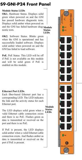
LEDs
LEDs, which provide visual status information, are provided on the CMM, NI, and power supply front panels. LEDs are used to indicate conditions, such as hardware and software status, temperature errors, link integrity, data flow, etc. For detailed LED descriptions, refer to the corresponding hardware compo-nent chapter (e.g., “Network Interface (NI) Modules”).
Power Checking Sequence
The power checking sequence is another built-in Availability feature. This feature helps regulate power in the switch whenever the switch is booted or an NI module is installed in the chassis.
The sequence is a joint effort between the CMM, the NI modules, and the power supplies. During the boot sequence, the primary CMM automatically compares the power consumption required by installed NIs with the power available from the power supplies. If there is not adequate power to support all NIs, the CMM will power on only the supported number of NIs, starting from the first NI slot position.
Important. During the power checking sequence, CMMs receive priority and are always powered on. NI modules are then powered on sequentially by slot position. In other words, the NI in slot 1 is powered on, then slot 2, then slot 3, etc. For information on slot positions, refer to Chapter 2, “Chassis and Power Supplies.”
Installing a New NI into a Running Chassis
2 Chassis and Power
Supplies
The OmniSwitch 9000 switches are available in three chassis configurations—the 18-slot OmniSwitch 9800 (OS9800), the 10-slot OmniSwitch 9700 (OS9700), and the 5-slot OmniSwitch 9600 (OS9600). This chapter includes detailed information on each of these chassis types. The topics include:
• Technical specifications on page 2-7.
• Switch mounting information on page 2-12.
• Power supplies and power supply redundancy on page 2-16.
• Temperature management on page 2-33.
• Chassis fan tray on page 2-35.
• Monitoring the chassis components via the Command Line Interface (CLI) on page 2-21.
OmniSwitch OS9600, OS9700, OS9800
OS9800-CMM OS9800-CMM 1x 3x 5x 7x 9x 11x 13x 15x 17x 19x 21x 23x OK1OK1OK2 22x 20x 18x 16x 14x 12x 10x 8x 6x 4x 1x 3x 5x 7x 9x 11x 13x 15x 17x 19x 21x 23x OK1OK2 22x 20x 18x 16x 14x 12x 10x 8x 6x 4x 1x 3x 5x 7x 9x 11x 13x 15x 17x 19x 21x 23x OK1OK2 22x 20x 18x 16x 14x 12x 10x 8x 6x 4x 1x 3x 5x 7x 9x 11x 13x 15x 17x 19x 21x 23x OK1 OK2 22x 20x 18x 16x 14x 12x 10x 8x 6x 4x 1 2 3 4 5 6 7 8 NI NI CMM PWR PS3PS2PS1 A B OS9-GNI-C24 OS9-GNI-C24 OS9-GNI-C24 OS9-GNI-C24 OS9600/OS9700-CMM OS9600/OS9700-CMM OS9-XNI-U2 OS9-XNI-U2 OS9-XNI-U2 OS9-XNI-U2
50/60Hz, 8.0/7.0/3.5 A 100/115/250V OVERTEMP DC OK AC OK 50/60Hz, 8.0/7.0/3.5 A 100/115/250V OVERTEMPDC OK AC OK 50/60Hz, 8.0/7.0/3.5 A 100/115/250V OVERTEMP DC OK AC OK
ETHERNET COSOLE/MDM ETHERNET CONSOLE/ MDM USB USB LINKACT OK1 OK2 CONTROL FABRICCONTROL FABRIC TEMP FAN PSU LINK ACT OK1OK2 TEMP FAN PSU OK1 OK2 LINK/ACT LINK/ACT 2 1 LINK/ACT LINK/ACT OK1 OK2 1 2 OK1OK2 1 2 OK1OK2 1 2 LINK/ACT LINK/ACT LINK/ACT LINK/ACT OS9-GNI-C24 A B 1x 3x 5x 7x 9x 11x 13x 15x 17x 19x 21x 23x OK1OK2 22x 20x 18x 16x 14x 12x 10x 8x 6x 4x OS9-GNI-C24 A B 1x 3x 5x 7x 9x 11x 13x 15x 17x 19x 21x 23x OK1 OK2 22x 20x 18x 16x 14x 12x 10x 8x 6x 4x OS9-GNI-C24 A B 1x 3x 5x 7x 9x 11x 13x 15x 17x 19x 21x 23x OK1OK2 22x 20x 18x 16x 14x 12x 10x 8x 6x 4x OS9-GNI-C24 A B 1x 3x 5x 7x 9x 11x 13x 15x 17x 19x 21x 23x OK1OK2 22x 20x 18x 16x 14x 12x 10x 8x 6x 4x OS9-GNI-C24 A B 1x 3x 5x 7x 9x 11x 13x 15x 17x 19x 21x 23x OK1OK2 22x 20x 18x 16x 14x 12x 10x 8x 6x 4x OS9-GNI-C24 A B 1x 3x 5x 7x 9x 11x 13x 15x 17x 19x 21x 23x OK1 OK2 22x 20x 18x 16x 14x 12x 10x 8x 6x 4x OS9-GNI-C24 A B 1x 3x 5x 7x 9x 11x 13x 15x 17x 19x 21x 23x OK1 OK2 22x 20x 18x 16x 14x 12x 10x 8x 6x 4x OS9-GNI-C24 A B 1x 3x 5x 7x 9x 11x 13x 15x 17x 19x 21x 23x OK1 OK2 22x 20x 18x 16x 14x 12x 10x 8x 6x 4x OS9-XNI-U2 OS9-GNI-C24 A B 1x 3x 5x 7x 9x 11x 13x 15x 17x 19x 21x 23x OK1 OK2 22x 20x 18x 16x 14x 12x 10x 8x 6x 4x OS9-XNI-U2 OS9-GNI-C24 A B 1x 3x 5x 7x 9x 11x 13x 15x 17x 19x 21x 23x OK1 OK2 22x 20x 18x 16x 14x 12x 10x 8x 6x 4x OS9-XNI-U2 OS9-GNI-C24 A B 1x 3x 5x 7x 9x 11x 13x 15x 17x 19x 21x 23x OK1OK2 22x 20x 18x 16x 14x 12x 10x 8x 6x 4x OS9-XNI-U2 OS9-GNI-C24 A B 1x 3x 5x 7x 9x 11x 13x 15x 17x 19x 21x 23x OK1 OK2 22x 20x 18x 16x 14x 12x 10x 8x 6x 4x
50/60Hz, 8.0/7.0/3.5 A 100/115/250V OVER TEMP DC OK AC OK
50/60Hz, 8.0/7.0/3.5 A 100/115/250V OVERTEMP DC OK AC OK
50/60Hz, 8.0/7.0/3.5 A 100/115/250V OVER TEMP DC OK AC OK
1 2 3 4 9 10 11 12 A B 5 6 7 8 13 14 15 16 NI NI CMM PWR PS4PS3 PS2PS1
50/60Hz, 8.0/7.0/3.5 A 100/115/250V OVER TEMP DC OK AC OK
OK1OK2 OK1 OK2 ACTLINK ACT LINK ACTLINK ACT LINK TX 2 RX TX 2 RX TX 2 RX TX 2 RX ACTLINK ACT LINK ACTLINK ACT LINK TX 1 RX TX 1 RX TX 1 RX TX 1 RX OK1 OK2 OK1OK2 CONTROL FABRIC TEMP FAN PSU
U S B
CONSOLE/MODEM ETHERNET LINK/ACT OK1 OK2 CONTROL FABRIC TEMP FAN PSU
U S B
OmniSwitch 9800
The OmniSwitch 9800 is a high performance switch offering 16 slots for Gigabit Ethernet and/or 10-Giga-bit Ethernet Network Interface (NI) modules. An additional two slots are reserved for primary and redun-dant Chassis Management Modules (CMMs). The OmniSwitch 9800 supports a maximum of four power supplies.
Note. Power supply requirements are based on the number of NIs installed in the chassis. Refer to
“Power Supplies” on page 2-16 for important information on power supplies and power supply
redundancy.
The following illustrations outline the major components of the OmniSwitch 9800 switch.
OmniSwitch 9800 Front View
1 2 3 4
9 10 11 12 A B
5 6 7 8
13 14 15 16
NI CMM NI PWR
PS4 PS3 PS2 PS1 OVER TEMP DC OK AC OK
50/60Hz, 8.0/7.0/3.5 A 100/115/250V
OVER TEMP DC OK AC OK
50/60Hz, 8.0/7.0/3.5 A 100/115/250V
OVER TEMP DC OK AC OK
50/60Hz, 8.0/7.0/3.5 A 100/115/250V
OVER TEMP DC OK AC OK
50/60Hz, 8.0/7.0/3.5 A 100/115/250V OS9-GNI-C24 1x 3x 5x 7x 9x 11x 13x 15x 17x 19x 21x 23x OK1 OK2 22x 20x 18x 16x 14x 12x 10x 8x 6x 4x OS9-GNI-C24 1x 3x 5x 7x 9x 11x 13x 15x 17x 19x 21x 23x OK1 OK2 22x 20x 18x 16x 14x 12x 10x 8x 6x 4x OS9-GNI-C24 1x 3x 5x 7x 9x 11x 13x 15x 17x 19x 21x 23x OK1 OK2 22x 20x 18x 16x 14x 12x 10x 8x 6x 4x OS9-GNI-C24 1x 3x 5x 7x 9x 11x 13x 15x 17x 19x 21x 23x OK1 OK2 22x 20x 18x 16x 14x 12x 10x 8x 6x 4x OS9-GNI-C24 1x 3x 5x 7x 9x 11x 13x 15x 17x 19x 21x 23x OK1 OK2 22x 20x 18x 16x 14x 12x 10x 8x 6x 4x OS9-GNI-C24 1x 3x 5x 7x 9x 11x 13x 15x 17x 19x 21x 23x OK1 OK2 22x 20x 18x 16x 14x 12x 10x 8x 6x 4x OS9-GNI-C24 1x 3x 5x 7x 9x 11x 13x 15x 17x 19x 21x 23x OK1 OK2 22x 20x 18x 16x 14x 12x 10x 8x 6x 4x OS9-GNI-C24 1x 3x 5x 7x 9x 11x 13x 15x 17x 19x 21x 23x OK1 OK2 22x 20x 18x 16x 14x 12x 10x 8x 6x 4x OS9-GNI-C24 1x 3x 5x 7x 9x 11x 13x 15x 17x 19x 21x 23x OK1 OK2 22x 20x 18x 16x 14x 12x 10x 8x 6x 4x OS9-GNI-C24 1x 3x 5x 7x 9x 11x 13x 15x 17x 19x 21x 23x OK1 OK2 22x 20x 18x 16x 14x 12x 10x 8x 6x 4x OS9-GNI-C24 1x 3x 5x 7x 9x 11x 13x 15x 17x 19x 21x 23x OK1 OK2 22x 20x 18x 16x 14x 12x 10x 8x 6x 4x OS9-GNI-C24 1x 3x 5x 7x 9x 11x 13x 15x 17x 19x 21x 23x OK1 OK2 22x 20x 18x 16x 14x 12x 10x 8x 6x 4x OS9-XNI-U2 OK1 OK2 ACT LINK ACT LINK RX TX RX TX 1 2 OS9-XNI-U2 OK1 OK2 ACT LINK ACT LINK RX TX RX TX 1 2 OS9-XNI-U2 OK1 OK2 ACT LINK ACT LINK RX TX RX TX 1 2 OS9-XNI-U2 OK1 OK2 ACT LINK ACT LINK RX TX RX TX 1 2 OS9800-CMM OS9800-CMM
C ONTR OL FAB R IC TE MP FAN P S U
US B CONSOLE/MODEM CONSOLE/MODEM
E THE R NE T
L INK /AC T OK1 OK2
C ONTR OL FAB R IC TE MP FAN P S U
US B
E THE R NE T
L INK /AC T OK1 OK2 OmniSwitch 9800
Front Rack Mount
Network Interface
Power Supplies (NI) Modules
Network Interface (NI) Modules Front Rack Mount
Flange
Flange
Grounding Lug
Chassis and Power Supplies OmniSwitch 9800
OmniSwitch 9800 Back View
Front Rack Mount
Front Rack Mount
Connectors for inline power supply. Airflow Exhaust Vents
(for power supplies)
Fan Tray (contains three fans) for chassis temperature control and airflow exhaust
OmniSwitch 9800 Technical Specifications
Total 10/100/1000 copper Ether-net ports available
768 (Fully-populated with OS9-GNI-C48T modules. No other NI module types installed.)
384 (Fully-populated with OS9-GNI-C24 and/or OS9-GNI-P24 modules. No other NI module types installed.)
Total 1000BaseSX Ethernet ports available
384 (Fully-populated with OS9-GNI-U24 modules. No other NI module types installed.)
Total 10-Gigabit Ethernet ports available
32 (Fully-populated with OS9-XNI-U2 modules, with each XNI containing two GBICs. No other NI modules installed.) 96 (Fully-populated with OS9-XNI-U6 modules, with each XNI containing six GBICs. No other NI modules installed.) Total slots available for network
interface (NI) modules
16
Total slots available for CMMs 2 Total bays for power supplies 4
Power 85 watts (approximate)
OmniSwitch 9800 Chassis Dimensions
Overall Width (including rack-mount flanges) 19 1/8 inches Chassis Width (rack-mount flanges not included) 17 9/16 inches
Height 29 3/4 inches
Height (rack units) 17 RU
Overall Depth (including required fan tray) 17 5/16 inches
Chassis and Power Supplies OmniSwitch 9700
OmniSwitch 9700
The OmniSwitch 9700 is a high performance switch offering eight slots for Gigabit Ethernet and/or 10- gigabit Ethernet Network Interface (NI) modules. Additional two slots are reserved for primary and redun-dant Chassis Management Modules (CMMs). The OmniSwitch 9700 supports a maximum of three power supplies.
Note. Power supply requirements are based on the number of NIs installed in the chassis. Refer to
“Power Supplies” on page 2-16 for important information on power supplies and power supply
redun-dancy.
The following illustrations outline the major components of the OmniSwitch 9700 switch.
OmniSwitch 9700 Front View
CONTROL
FABRIC
TEMP
FAN
PSU CONTROL
FABRIC
TEMP
FAN
PSU
USB
COSOLE/MODEM
ETHERNET USB
COSOLE/MODEM
ETHERNET
LINK/ACT LINK/ACT
LINK/ACT LINK/ACT LINK/ACT LINK/ACT
LINK/ACT LINK/ACT LINK/ACT LINK/ACT
OS9-GNI-C24 OS9-GNI-C24 OS9-GNI-C24 OS9-XNI-U2 OS9-XNI-U2 OS9-XNI-U2 OS9-XNI-U2
OS9600/OS9700-CMM OS9600/OS9700-CMM
OS9-GNI-C24
OmniSwitch 9700
Air Intake Vent Front Rack Mount
Power Supplies
Network Interface (NI) Modules Front Rack Mount
Flange Flange
OmniSwitch 9700 Back View
Front Rack Mount Front Rack Mount
Connectors reserved for use with inline power supply.
Airflow Exhaust Vents (for power supplies)
Fan Tray (contains three fans) for chassis temperature control and airflow exhaust
Chassis and Power Supplies OmniSwitch 9700
OmniSwitch 9700 Technical Specifications
Total 10/100/1000 copper Ether-net ports available
384 (Fully-populated with OS9-GNI-C24 and/or OS9-GNI-P24 modules. No other NI module types installed.)
Total 1000Base SX fiber Ether-net ports available
192 (Fully-populated with OS9-GNI-U24 modules. No other NI module types installed.)
Total 10-Gigabit Ethernet ports available
16 (Fully-populated with OS9-XNI-U2 modules, with each XNI containing two XFPs. No other NI modules installed.) 48 (Fully-populated with OS9-XNI-U6 modules, with each XNI containing six XFPs. No other NI modules installed.) Total slots for network interface
(NI) modules
8
Total slots for CMM 2
Total bays for power supplies 3
Power 50 W (approximate)
OmniSwitch 9700 Chassis Dimensions
Overall Width (including rack-mount flanges) 19 1/8 inches Chassis Width (rack-mount flanges not included) 17 9/16 inches
Height 19 1/4 inches
Height (rack units) 11 RU
Overall Depth (including required fan tray) 17 5/16 inches
OmniSwitch 9600
The OmniSwitch 9600 is a high performance switch offering four slots for Gigabit Ethernet and/or 10 gigabit Ethernet Network Interface (NI) modules. An additional one slot is reserved for the primary Chassis Management Module (CMM). The OmniSwitch 9600 supports a maximum of two load sharing power supplies on the front panel and there are optional power connectors, which consist of three DB-25 connectors mounted on the rear panel of the chassis for PoE applications. Either OS9-IP-SHELF or 360W/510W power supplies can be used. The first two connectors support OS9-IP-SHELF power supplies and the third connector supports 360W/510W power supplies.
Note. Power supply requirements are based on the number of NIs installed in the chassis. Refer to
“Power Supplies” on page 2-16 for important information on power supplies and power supply
redun-dancy.
The following illustrations outline the major components of the OmniSwitch 9600 switch:
OmniSwitch 9600 Front View
NI 4 2 NI CMM 3 1 OmniSwitch 9600 OS9-GNI-C24 OS9-GNI-C24 CO N TR O L FA BR IC
TEMP FAN PSU
USB
C
O
SOLE/MODEM ETHERNET LINK/A
CT OS9600/OS9700-CMM LINK/A CT LINK/A CT OS9-XNI-U2 LINK/A CT LINK/A CT OS9-XNI-U2 OVERTEMP
DC OK
AC
OK
OVERTEMP
DC OK
AC O K OK2 OK1 OK2 OK1 OK2 OK1 OK2 OK1 OK2 OK1
Front Rack
Mount
Flange
CMM
Front
Rack-Mount Flange
Power SuppliesNetwork
Chassis and Power Supplies OmniSwitch 9600
OmniSwitch 9600 Back View
Fan Tray (contains four fans) for chassis temperature control and airflow exhaust
Front rack mount flange
Front rack mount
flange
Connectors reserved for use with inline power supply.
s
OmniSwitch 9600 Technical Specifications
Total 10/100/1000 copper Ether-net ports available
192 (Fully-populated with OS9-GNI-C24 and/or OS9-GNI-P24 modules. No other NI module types installed.)
Total 1000Base SX fiber Ether-net ports available
96 (Fully-populated with OS9-GNI-U24 modules. No other NI module types installed.)
Total 10-Gigabit Ethernet ports available
8 (Fully-populated with OS9-XNI-U2 modules, with each XNI containing two XFPs. No other NI modules installed.)
24 (Fully-populated with OS9-XNI-U6 modules, with each XNI containing six XFPs. No other NI modules installed.) Total slots for network interface
(NI) modules
4
Total slots for CMM 1
Total bays for power supplies 2
Power 50 W (approximate)
OmniSwitch 9600 Chassis Dimensions
Width 19 inches
Height 9.575 inches
Chassis and Power Supplies Chassis Slot Numbering
Chassis Slot Numbering
The term slot refers to the position at which a CMM or NI module is installed in chassis. CMM slot posi-tions are designated as Slot A and Slot B. On OS9800 switches, NI slot numbers range from 1 to 16. On OS9700 switches, NI slot numbers range from 1 to 8. On OS9600 switches, NI slot numbers range from 1 to 4.
Note. The OS9600 contains only one CMM slot.
Power supply bays are also given specific slot numbers. On OS9800 switches, power supply slot numbers are designated PS-1 through PS-4 from top to bottom. On OS9700 switches, power supply slot numbers are designated PS-1 through PS-3 from top to bottom. On OS9600 switches, power supply slot numbers are designated PS-1 and PS-2 from top to bottom.
1 2 3 4
9 10 11 12
A B 5 6 7 8
13 14 15 16
NI CMM NI PWR
PS4 PS3 PS2 PS1 OmniSwitch 9800
1 2 3 4
A B
5 6 7 8
NI NI
CMM PWR
PS3 PS2 PS1
OmniSwitch 9700
NI
4
2
NI
CMM
3
1
OmniSwitch 9600
1 2 3 4
A B
5 6 7 8
PS-1
PS-2
PS-3
PS-1
PS-2
1
2
3
4
A
1
2 3 4
A B
5 6 7 8 PS-1
10
11
12
13 14 1516
OS9700 (10-Slot Chassis)
9
PS-2
PS-4
Viewing Chassis Slot Information
To view basic slot information via the CLI, enter the show module command at the CLI prompt:
-> show module
To view more detailed slot information, use the show module long form of this command. For example:
-> show module long
Mounting the Switch
Important. Two people are required when lifting the chassis. Due to its weight, lifting the chassis unas-sisted can cause personal injury. If you need to move the switch, be sure to power it down and remove all modules and power supplies. For instructions on removing CMM or NI modules, refer to Chapter 5,
“Network Interface (NI) Modules.” For instructions on removing power supplies, refer to “Removing a
Power Supply” on page 2-30.
Note. Due to their weight and airflow requirements, OS9800, OS9700, and OS9600 switches cannot be wall-mounted.
Airflow Considerations
Be sure that your switch is placed in a well-ventilated, static-free environment. Always allow adequate clearance at the front and sides of the switch, as well as behind the switch’s fan unit (located at the top-rear of the chassis). The following top-view diagram shows recommended minimum clearances for adequate airflow.
Chassis Top View
Note. Never obstruct the air intake vents located at the bottom-front and bottom-sides of the chassis or the
}
}
Rear. 6 inches minimumat rear of chassis fan unit.
Chassis and Power Supplies Mounting the Switch
Rack-Mounting
Refer to the important guidelines below before installing the OmniSwitch 9800/9700/9600 chassis in a rack.
• Be sure that all modules and power supplies are removed before rack-mounting the switch. For instruc-tions on removing CMM or NI modules, refer to Chapter 5, “Network Interface (NI) Modules.” For instructions on removing power supplies, refer to “Removing a Power Supply” on page 2-30.
• Rack-mounting the chassis requires three people—two people to hold the chassis and position it in the rack and a third person to secure the chassis to the rack using the attachment screws.
• The chassis has two integral rack-mount flanges that support standard 19-inch rack mount installa-tions. Refer to page 2-15 for information on optional rack-mounting hardware.
• Alcatel-Lucent does not provide rack-mount screws. Use the screws supplied by the rack vendor.
• To prevent a rack from becoming top heavy, it is recommended that you install the switch at the bottom of the rack whenever possible.
• If you are installing the switch in a relay rack, be sure to install and secure the rack per the rack manu-facturer’s specifications.
• Refer to page 2-12 for important chassis airflow recommendations before installing.
To rack-mount the switch, follow the steps below:
1 Mark the holes on the rack where the chassis is to be installed.
2 Using two people, lift and position the chassis until the rack-mount flanges are flush with the rack post. 3 Align the holes in the flanges with the rack holes you marked in step 1.
4 Once the holes are aligned, use a third person to insert a screw through the bottom hole on each flange. Tighten both screws until they are secure.
OmniS wit ch 9700
1 2
3 4
5 6
7 8 NI
NI CMM
PWR PS3 PS2 PS1 A
5 Once the screws at the bottom of each flange are secure, install the remaining screws. Be sure that all screws are securely tightened.
To rack-mount the patch panel, follow the steps explained below:
1 Remove all the connections before rack mounting the patch panel.
2 Rack-mounting the patch panel requires two people— one person to hold the patch panel and position it in the rack and a second person to secure the patch panel to the rack using the attachment screws.
3 Mark the holes on the rack where the patch panel is to be installed.
4 Using one person, lift and position the patch panel until the rack-mount flanges are flush with the rack post.
5 Align the holes in the flanges with the rack holes you marked in step 3.
Chassis and Power Supplies Mounting the Switch
Optional Rack-Mounting Hardware
All OmniSwitch 9000 switches are shipped with integral front rack-mount flanges. These flanges support standard 19-inch rack mount installations. If you have non-standard rack-mount requirements,
Alcatel-Lucent offers optional hardware for the following applications:
• 23-inch rack installations
• Side-mount hardware for additional support
For information on this optional rack mounting hardware, contact your Alcatel-Lucent representative.
Standalone
The OmniSwitch 9000 switches can be installed unmounted as a standalone unit. Be sure that the installa-tion locainstalla-tion is a stable, flat surface that can accommodate the fully-populated weight of all switches being installed. One fully-populated OmniSwitch 9800 weighs approximately 188 pounds (85 kilograms), a OmniSwitch 9700 weighs approximately 128 pounds (58 kilograms); a fully-populated OmniSwitch 9600 weighs approximately 66 pounds (30 kilograms).
Note. OmniSwitch 9000 switches must be installed “right side up”. Never attempt to operate a switch while it is lying on its side.
To install the switch as a standalone unit, follow the steps below:
1 Use two or more people to move and position the unpopulated chassis upright on the floor or bench where it is to be installed.
2 Be sure that adequate clearance has been provided for chassis airflow and that you have placed the chassis within reach of all required AC outlets. For recommended airflow allowances, refer to page 2-12.
Note. For detailed information on installing additional components and connecting the switch, refer to the
Power Supplies
The OmniSwitch 9800 supports a total of four power supplies; the OmniSwitch 9700 supports a total of three power supplies; the OmniSwitch 9600 supports a total of two power supplies (refer to page 2-27 for important redundancy information). The power supplies are installed in the power supply bays located at the right side of the chassis. See page 2-11 for a slot diagram showing the power supply bays.
Power Supply Front Panel
OVER TEMP DC OK AC OK
50/60Hz, 8.0/7.0/3.5 A100/115/250V
AC OK (Top LED). Displays solid green when the power supply’s AC cur-rent status is OK and the power supply is operating. Off when the power supply is not operating.
DC OK (Middle LED). Displays solid green when the power supply’s DC cur-rent status is OK and the power supply is operating. Off when the power supply is not operating.
OVER TEMP (Bottom
LED). Off when the power
supply is operating under supported temperature con-ditions.
Displays solid amber when a temperature error is detected in the power supply hous-ing. If a temperature error is detected, check for an air-flow obstruction at the air intake vent or at the back of the chassis. If no airflow obstruction exists, remove or replace the power supply immediately. Refer to the sections below for important information on replacing power supplies and power supply redundancy.
Power Switch.
indicates on position; indicates off position. Power
Supply LEDs
Power Connector Socket. Type IEC-320-C13. Supports one 10 amp power cord.
It is recommended that you use Alcatel-Lucent provided power cords.
Air Intake Vent. The air intake vent provides cooling and temperature control for the power supply. Maintain a front clearance of at least six inches to ensure proper airflow.
For additional airflow
informa-tion, refer to page 2-40.
Power Cord Retainer. Alcatel-Lucent provides a white nylon cable retainer with each power supply. This retainer is used to secure the power cord so that it cannot be accidentally pulled from the socket.
For information on using this
Chassis and Power Supplies Power Supplies
OmniSwitch 9000 Power Supply Technical Specifications
Input Voltage 100/115/220/230V
Frequency 50/60Hz
Input Power (per supply) 8/7/3.5/3.5 Amps maximum
600 Watt DC-to-DC Power Supply
In addition to AC power supplies, OmniSwitch 9000 switches offer DC power support (OS9-PS-0600D). As with the AC power supplies, DC supplies are installed in the power supply bays located along the right side of the chassis. See page 2-11 for a slot diagram showing the power supply bays.
OVER TEMP DC OUT OK
DC IN OK
20A 48 - 60 V
A A A A (-) (-) (+) (+) DC IN OK (Top LED).
Displays solid green when the power supply’s DC
input status is OK and the power supply is operating. Off when the power supply is not operating.
DC OUT OK (Middle LED).
Displays solid green when
the power supply’s DC
out-put status is OK and the
power supply is operating. Off when the power supply is not operating.
OVER TEMP (Bottom
LED). Off when the power
supply is operating under supported temperature con-ditions.
Displays solid amber when a temperature error is detected in the power supply hous-ing. If a temperature error is detected, check for an air-flow obstruction at the air intake vent or at the back of the chassis. If no airflow obstruction exists, remove or replace the power supply immediately. Refer to the sections below for important information on replacing power supplies and power
supply redundancy. Power Switch.
indicates on position; indicates off position. Power
Supply
LEDs DC Power Connector Socket.
Anderson Powerpole modular connector, or equivalent. The connector socket ships factory-installed in the power supply’s front panel.
For information on the DC power connectors, including notes on connecting the power
cable, refer to page 2-19.
Safety Ground Connector. A safety ground is provided on each power supply and is used to ground the OS9000 chassis.
For information on properly connecting the ground, refer
Air Intake Vent. The air intake vent provides cooling and temperature control for the power supply. Maintain a front clearance of at least six inches to ensure proper airflow.
For additional airflow
informa-tion, refer to page 2-40.
Chassis and Power Supplies Power Supplies
DC Power Supply Connection
In the current release, a 15-inch pre-assembled cable harness is shipped with each DC-to-DC power supply. You can plug this cable harness directly into the DC power connector on the power supply. Refer to the important information below before connecting a DC power supply.
Connecting the DC Cable Harness to the Chassis Power Supply
When plugging in the cable, insert the connector end of the cable harness into the power supply connector until it clicks firmly into place. This is an indication that the connector is secure and properly seated.
Connecting the DC Cable Harness to the DC Power Source
The other end of the cable harness is bare. Users must assemble and connect this end to the DC power source or to a cable coming from the power source. In addition to following the important guidelines listed below, be sure to consult specifications for the DC power source more information.
• Connect the power supply to a reliably grounded 48VDC SELV source.
• The branch circuit overcurrent protection must be rated 30A.
• Use 10AWG copper conductors.
• A readily accessible disconnect device that is suitably approved and rated shall be incorporated in the field wiring.
• The power supply shall be installed in a restricted access location.
• The power supply shall used with an Anderson Power Products model 1460G1 cord connector body. OmniSwitch 9000 DC Power Supply Technical Specifications
Input Voltage -48VDC to -60VDC
Ambient Temperature 0–70 degrees Celsius (operating) -40–85 degrees Celsius (non-operating)
Humidity 5% to 90% Relative Humidity (Operating)
0% to 95% Relative Humidity (Storage)
Altitude 10,000 feet above sea level and 32 degrees Celsius ambient air temperature maximum (operating)
Chassis Power Supply Module Support
This table provides general guidelines only and applies to most chassis hardware configurations. These guidelines offer a quick way to determine the minimum number of power supplies required for the current chassis configuration. For a definitive approach to determining the minimum amount of power required,
you must follow the steps outlined in “Monitoring Chassis Power” on page 2-21.
OS9600 OS9700 OS9800
One Power Supply Supports one CMM and up to four NI modules.
Supports one or two CMMs and up to seven NI modules.
Supports one or two CMMs and up to six NI modules.
Two Power Supplies Provides power supply redundancy.
Supports one or two CMMs and up to eight NI modules.
Supports one or two CMMs and up to 16 NI modules.
Three Power Supplies N/A Provides power sup-ply redundancy.
Provides power supply redundancy (if only one
power supply is removed or goes down unexpectedly). Refer to page 2-27 for more information on power sup-ply redundancy.
Four Power Supplies N/A N/A Provides complete power
supply redundancy (if up to
Chassis and Power Supplies Monitoring Chassis Power
Monitoring Chassis Power
Adding Network Interface (NI) modules and removing power supplies significantly affects the overall power budget for the switch. Therefore, before adding a module or removing a power supply, you must first verify that the current chassis power supports the change.
Refer to the sections below for important information on monitoring the current chassis power.
Checking Chassis Power Before Adding a Module
Depending on the module type, adding a single module can add up to 88 watts to the existing chassis power requirements. The table below shows the requirements for CMM and NI modules currently supported on OS9800, OS9700 and OS9600 switches:
Note. Technical specifications for NI modules are provided in Chapter 5, “Network Interface (NI) Modules.”
As soon as a module is inserted, and the module’s connectors make contact with the chassis backplane, the power requirements take effect. If there is no adequate power, the incoming module will not power on. Additional power errors may also occur, which can interrupt data flow on the switch. Therefore, it is important to manually check the current chassis power before adding a module.
For examples, showing effective ways to check the current chassis power, refer to the examples beginning
on page 2-22.
Module Type Power Required, in Watts
OS9800-CMM 88
OS9600/OS9700-CMM 33
OS9-GNI-C24 51
OS9-GNI-P24 54
OS9-GNI-C20L 55
OS9-GNI-C48T 105
OS9-GNI-U24 55
OS9-XNI-U6 77
Example 1: Adequate Power to Add a Module
1 First, enter the show chassis command. A screen similar to the following displays:
-> show chassis
Model Name: OS9700, Description: OS9700, Part Number: 901748-ÿÿÿ, Hardware Revision: 202,
Serial Number: 1467014A, Manufacture Date: NOV 16 2005, Admin Status: POWER ON, Operational Status: UP, Free Slots: 8, Power Left: 535, Number Of Resets: 2
Note that the “Power Left” field in the table output shows 535. This value, displayed in watts, indicates that 535 watts are available for additional hardware (e.g., CMM and NI modules).
2 Next, tabulate the power requirements for all modules to be added. For example, let’s say that the following modules are to be added to the chassis:
• OS9600/OS9700-CMM (33 watts)
• OS9-GNI-C24 (54 watts)
• OS9-GNI-C24 (54 watts)
• OS9-GNI-C24 (54 watts)
• OS9-XNI-U2 (36 watts)
The total power required for all incoming modules is 231 watts. Even after the 231 watts are allocated to the incoming modules, the chassis will retain 304 unused watts. The modules listed above can be safely added to the chassis.
3 After the modules have been installed, re-enter the show chassis command to confirm the results:
-> show chassis
Model Name: OS9700, Description: OS9700, Part Number: 901748-ÿÿÿ, Hardware Revision: 202,
Serial Number: 1467014A, Manufacture Date: NOV 16 2005, Admin Status: POWER ON, Operational Status: UP, Free Slots: 3, Power Left: 304, Number Of Resets: 2
Chassis and Power Supplies Monitoring Chassis Power
Example 2: Inadequate Power to Add a Module
1 Enter the show chassis command. A screen similar to the following displays:
-> show chassis
Model Name: OS9700, Description: OS9700, Part Number: 901748-ÿÿÿ, Hardware Revision: 202,
Serial Number: 1