75:2 (2015) 97–103 | www.jurnalteknologi.utm.my | eISSN 2180–3722 |
Jurnal
Teknologi
Full Paper
S
PHERE
E
NCAPSULATED
O
RIENTED
-D
ISCRETE
O
RIENTATION
P
OLYTOPES
(S-D
OP
)
C
OLLISION
C
ULLING FOR
M
ULTI
-,
R
IGID
B
ODY
D
YNAMIC
Norhaida Mohd Suaib
a*, Abdullah Bade
b, Dzulkifli Mohamad
aa
Faculty of Computing Universiti Teknologi Malaysia 81310 UTM
Johor Bahru, Johor, Malaysia
b
School of Science & Technology, Universiti Malaysia Sabah, Kota
Kinabalu, Sabah, Malaysia
Article history Received 3 December 2013 Received in revised form
2 July 2014 Accepted 25 November 2014
*Corresponding author
[email protected]
Graphical abstract
Abstract
This paper discusses on sphere encapsulated oriented-discrete orientation polytopes (therefore will be referred to as S-Dop) collision culling for multiple rigid body simulation. In order to improve performance of the whole simulation system, there are available options in sacrificing the accuracy over speed by using certain approximation techniques. The aim of this research is to achieve excellent performance through implementation of suitable culling technique, without jeopardizing the resulting behavior so that the simulation will still be physically plausible. The basic idea is to identify the highly probable pairs to collide and test the pair with a more accurate collision test in broad-phase collision detection, before the pair is passed to a more costly stage. Results from the experiments showed that there are a number of ways to implement the sphere encapsulated or-Dops (S-Dop) collision culling on a multiple rigid body simulation depending on the level of performance needed.
Keywords: Collision culling, collision detection, rigid body, bounding volume, boundary representation
© 2015 Penerbit UTM Press. All rights reserved
1.0 INTRODUCTION
There are many computer-simulated environments integrated within our daily life. Virtual environment, computer games, special effects in entertainment industry, engineering, medical, education and training are some of the fields that gain benefit from realistic computer-simulated environment. A realistic computer-simulated environment does not only refer to how realistic things look but also how they move and behave. Therefore, apart from rendering issues, virtual objects’ physical properties involved need to be catered as well.
Objects in a computer-simulated environment are mainly represented by numbers. These numbers can represent the vertices for polygonal meshes or a set of control points for implicit mathematical functions. 3D surfaces that users interact with visually are generated
based on these numbers. Objects may have volumetric information, but most of the time, these virtual objects only have surface information. Originally physics are not involved in object representation, so there is a need to involve physics and dynamics in order to imitate objects’ behavior in physical world.
98 Norhaida, Abdullah & Dzulkifli / Jurnal Teknologi (Sciences & Engineering) 75:2 (2015) 97–103
motion involved, but collision detection is a pre-requisite to the right responses.
The whole process of collision detection and collision response is called collision handling. The problem may not be complicated if only two objects are involved, but the complexity of the problem increases as the number of objects involved increases. This paper focuses on the efforts to reduce the number of pairwise testing for collision culling for multi-body and rigid-body objects undergoing motion. The rest of the paper is divided into Section 1-Introduction, followed by a discussion on issues in collision detection for rigid body dynamics in Section 2. Next, research framework will be covered in Section 3. The method used will be discussed in Section 4, followed by experimental layout in Section 5. Result and discussion will be presented in Section 6 and Section 7 concludes this paper.
2.0 ISSUES IN COLLISION DETECTION FOR
RIGID-BODY MOTION
Collision detection has been in the limelight in computer graphics research arena at least since three decades ago [1-3] and is still an active research area [4]. The basic problems of collision detection were mostly inspired from computational geometry and robotics research. Based on these, the application areas became widespread: for example in computer graphics, virtual environment, physically-based modeling, engineering, medical and molecular modeling [2, 5, 6] to name a few.
Objects involved in computer graphics simulation may either fall into rigid bodies or deformable/soft objects category. Viewed from kinematics point of view there will be another category; that is the particle mass. Both rigid bodies and deformable objects are made of particle masses, but the difference is that there is enough force to keep particles in a rigid body in place throughout the simulation. Therefore rigid body objects maintain the size and shape. External forces acting on particles in a deformable body may result in a change of shape. Animating rigid bodies involve a change of position/placement and optionally a change of orientation due to rotation. Animating deformable objects might involve a change of shape as well, and there are many variables to be updated.
Collision detection is involved as part of the process in computer graphics simulation in order to generate appropriate system response. The main simulation loop is seen as Figure 1. Collision detection pipeline usually comprises of a two-phase filtering process: broad-phase and narrow-broad-phase collision detection. Commercial physics library (for example; Bullet1, PhysX2
and Open Dynamics Engine-ODE3) also employ
several level of filtering in their collision detection pipeline [3].
1https://developer.nvidia.com/physx 2 http://bulletphysics.org/wordpress/
Figure 1 The basic simulation loop
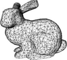
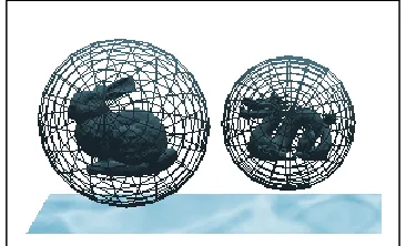
Figure 2 shows an example of a 3D object represented as triangular meshes. Generally, collision detection is performed by checking for intersections between two objects. For objects represented by triangular meshes, it is desirable to check if a triangle of an object intersects with a triangle of a second object. Pairs of triangular meshes that are found to be in intersection indicate that there is collision between the two objects. However, checking for intersections between every pair of triangles in the scene is far too time-consuming especially if there are multiple objects involved. Therefore there is a choice of using approximation techniques such as bounding volume. An example of collision detection using bounding sphere as the bounding volume is shown as Figure 3. (For a thorough discussion and information on collision detection and bounding volumes, readers are advised to refer to [5] and [7]).
Figure 2 A 3D object represented as triangular meshes
Figure 3 Collision detection between two objects based on bounding sphere
In real life, time is a continuous variable. However, time is seldom sampled at discrete time steps in computer graphics simulation. This kind of approximation is acceptable for common computer graphics applications that emphasis speed and robustness rather than accuracy, such as in computer games. The same approach is used for collision detection; most of the time discrete collision detection is used but there is sometimes a need to use continuous collision detection. Continuous collision detection will not be covered in this paper as the focus is more on discrete collision detection for multiple rigid body simulation.
As mentioned before, the collision detection problem may not be very complicated if only two objects are involved, but the complexity of the problem increases as the number of objects involved increases. A scene involving n objects requires n2 tests.
There are two types of objects incorporated into a virtual environment–some of them are static, and some are dynamic. Examples of static objects are structures and stationary objects while some of the examples of dynamic objects are like virtual human, cars, waving flags and other moving objects. Comparatively, it is easier to handle interaction involving static objects but it becomes more complex when it involves dynamic objects. Real-time collision detection for most of computer graphics applications usually employs efficient and fast collision detection technique that has the ability to report any collision as accurate as possible. Spending too much time on collision handling may result in lower frame rates. In some applications, we have a choice to trade speed over accuracy in order to achieve interactive frame rates. Virtual prototyping for example, requires high accuracy but it does not put emphasis on real-time execution. On the other hand, computer game requires interactive frame rates and some approximation may be incorporated into collision detection and response algorithm. However, neglecting too much accuracy may result in unrealistic behavior.
Bounding volume is a popular broad-phase collision detection approach [8] in simulations involving n-body objects [2]. Collision tests based on bounding volumes usually employ efficient methods such as using separating axis theorem, and this offers an advantage over other methods[9]. Simple bounding volume
requires less computation during bounding volume construction, updates and its collision tests thus resulting in higher frame rates. However, it may not be compact and can contain more empty corners compared to a more accurate (and costly) bounding volume. Some of the conventional bounding volumes, arranged in a sequence of speed versus accuracy are shown in Figure 4.
Figure 4 Simplicity versus accuracy[2]
Bounding volume techniques that are shown in Figure 4 are bounding sphere, Axis-aligned bounding box (AABB), oriented bounding box (OBB), discrete orientation polytopes (k-DOPs) and Oriented-Discrete Orientation Polytopes[5] (or-Dops).
Adaptations of time-critical collision detection[10] are mostly done through bounding volume implementation, as discussed in [2]. The essence of time-critical collision detection “…is trading accuracy for speed”[10]. Achieving excellent frame rates is the main concern for this research, and at the same time without jeopardizing too much accuracy.
3.0 RESEARCH FRAMEWORK
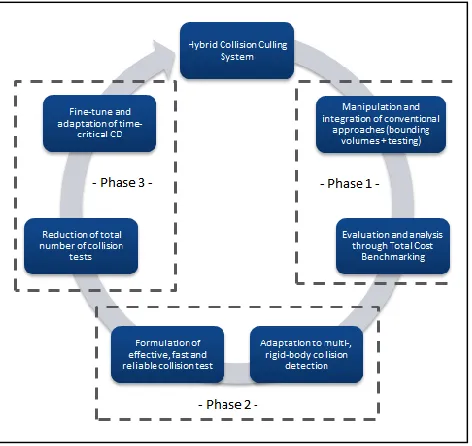
There are three main phases of studies conducted with the aim to meet the research goal as stated in previous section, (for generality, the proposed method will be initially referred to as ‘Hybrid Collision Culling System’) as follows:
a) First phase: finding out how to manipulate and
integrate conventional approaches in collision detection by a series of testing and through Total Cost Benchmarking analysis. Related experiments were done in [2]. Total Cost Benchmarking that takes into account the costs for one-off construction, collision tests and bounding volume updates, and also the average frame per second (fps) were used to evaluate the performance of the bounding volume candidates. The findings showed that manipulation of bounding sphere and or-Dops has the potential for an option towards a better collision culling process. Therefore a hybrid collision culling method that manipulates bounding sphere and or-Dops was introduced.
b) Second phase: adaptation of findings from the first
phase into multiple rigid-bodies simulation. Phase 2 includes adaptation of the hybrid collision culling
Simpler BV
100 Norhaida, Abdullah & Dzulkifli / Jurnal Teknologi (Sciences & Engineering) 75:2 (2015) 97–103
method (findings from the first phase) into multiple rigid-bodies simulation. Initial results that only cover the fps performance was previously reported in [2] without further analysis. Complete analysis will be discussed in the following sections.
c) Third phase: finding out how to further improve the
findings from Phases 1 and 2, so that the total number of collision tests can be reduced and also finding ways to adapt Time Critical Collision Detection concept.
Figure 5 illustrates the research framework as discussed above, while further discussion on the formulation of techniques will be covered in the following section.
Figure 5 Research framework
Total Cost Benchmarking. A modified Total Cost
Benchmarking function was used [2] as shown as Equation 1:
T = Nu x Cu + Nv x Cv + Co (1)
Where
T: total cost function for interference detection,
Nv: number of bounding volume pair overlap tests
Cv: cost of testing a pair of bounding volumes
(overlap)
Nu: number of bounding volumes updated,
Cu: cost of average bounding volume update,
Co: indicates cost for one time processing, in this
case, the construction cost
4.0 SPHERE-ENCAPSULATED OR-DOPS
(S-DOP)
The main purpose of collision culling is to reduce collision tests by identifying and culling away unnecessary pairs. Broad-phase collision detection does not necessarily employ a one-step collision test. As can be seen from Figure 6, the broad-phase collision detection may incorporate a series of tests [3]. This figure supported the initial inspiration of a two-phase process collision culling process in order to achieve simple, fast and reliable collision culling method.
Figure 6 The typical design of a collision detection pipeline [3]
101 Norhaida, Abdullah & Dzulkifli / Jurnal Teknologi (Sciences & Engineering) 75:2 (2015) 97–103
Figure 7 Collision culling process
Above example illustrates a single collision culling process. In a scene involving multiple objects, there are a few options on how to conduct or-Dops tests on identified PCS:
a) sequentially: each PCS will be immediately tested
based on or-Dops test
b) in batches: all of the PCS will be collected and put
into a PCS list that will be tested after all pairs have been tested in the first phase (sphere-sphere collision test)
c) only to object-of-interest: this was an adaptation from a first-person shooter (FPS) game where the focus of game is through the first-person perspective (player’s perspective). In a FPS game, the player only sees and targets what are in front of him and things outside of his viewport are not immediately visible. In the experiment, only the objects that are identified as PCS will undergo the or-Dops collision test (full S-Dop test). Other objects that are further away will only be tested using single sphere-sphere collision test.
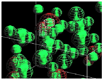
Figure 8 and 9 respectively show the implementation of S-Dop collision culling on all objects, and on an object of interest.
Figure 8 S-Dop collision culling on all objects
Figure 9 S-Dop collision culling on object-of-interest
5.0 EXPERIMENTAL LAYOUT
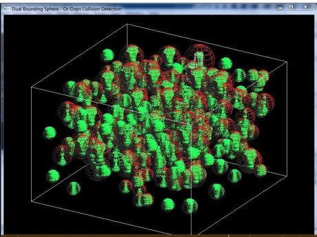
S-Dop collision culling was implemented on multiple *.tri objects. A scene involving combination of dynamic and some static objects inside a box was used. Dynamic objects are initially assigned with different velocity and allowed to move as in rigid body motion, so that there will be collisions among these objects. For the purpose of the experiment, objects are allowed to go through each other but collisions will be detected and recorded. A change of colour will visually indicate collision between two objects. Simple physics enforced on these objects results in a change of direction once they hit the boundary of the box. This is to ensure that they will not penetrate the walls. Collisions with walls are set to be fully elastic so that there will be no loss of energy. Based on the conservation of momentum:
m.v + m’.v’ = 0 (2)
where
m = mass (before collision), v = velocity (before collision), m’ = mass (after collision), v’ = velocity (after collision).
Since there will be no loss in mass, and the momentum will be conserved:
v’ = -v (3)
resulting in a change of direction after collisions.
A number of tests were conducted to see the performance of S-Dop collision culling against the basic conventional bounding volumes involved (sphere and or-Dops). These involved different numbers of objects involved: 50, 150, 350 and 500 objects. The first part is to see the performance based on frames per second (FPS). Simulation of multiple rigid body dynamics without collision detection (no bounding volume employed) was implemented as a benchmark or control experiment. This is to test if the
(i)
(ii)
(iii) (i)
(ii)
(iii)
(i)
(ii)
102 Norhaida, Abdullah & Dzulkifli / Jurnal Teknologi (Sciences & Engineering) 75:2 (2015) 97–103
performance (in terms of FPS) varies between the three options in the implementation of the S-Dop collision culling as outlined in the previous section. It could also be used as a test to see if any of the methods is up to the performance of the control experiment.
Sequential tests of sphere followed by or-Dops, batch processing the collision tests and S-Dopcollision culling on object-of-interest were compared against sphere, or-Dops and no bounding volume simulation (which acts as the control experiment). Screen captures of the experiments are presented as Figures 10 and 11.
Figure 10 Experiment on S-Dop on all objects
Figure 11 Experiment on S-Dop on object-of-interest
The second part of the experiment was designed to see the number of collisions detected compared to the number of tests conducted. This is presented in percentage; the higher percentage is desirable as it indicates the more useful tests conducted.
6.0 RESULTS AND DISCUSSION
6.1 Part 1
Results based on the frames per second (FPS) of multiple rigid body motion involving 500 objects are shown as Figures 12 and 13. Simulation without bounding volume (indicated as ‘No BV’) that acts as a control experiment shows the highest FPS as expected, followed by sphere bounding volume (labelled as ‘Sphere’).
Figure 12 FPS for 500 objects in a relatively small box (crowded environment)
FPS performance dropped if all objects employed the S-Dop collision culling on all objects (labelled as ‘ALL S-Dop’), but it still outperforms the homogeneous or-Dops implementation. Sequential S-Dop collision culling approach (‘Seq S-Dop’) where the PCS was immediately tested using or-Dops test showed an improved performance if there is a need to implement S-Dop collision culling method on all objects.
Figure 13 FPS for 500 objects in a relatively small box showing
the excellent FPS recorded for S-Dopcollision culling on an
object-of-interest (OoI)
The frame rates can reach to almost the performance of the control experiment when S-Dop collision culling was employed on a particular object-of-interest (‘OoI’); showing similarity with the
0 2 4 6 8 10 12 14
1 9 17 25 33 41 49 57 65 73 81 89 97
FP
S
Time (s)
FPS for 500 Objects
No BV Sphere Or-Dops Seq S-Dop ALL S-Dop
0 2 4 6 8 10 12 14
1 9 17 25 33 41 49 57 65 73 81 89 97
FP
S
Time (s)
FPS for 500 Objects
performance of sphere bounding volume. This is outstanding as compared to others.
6.2 Part 2
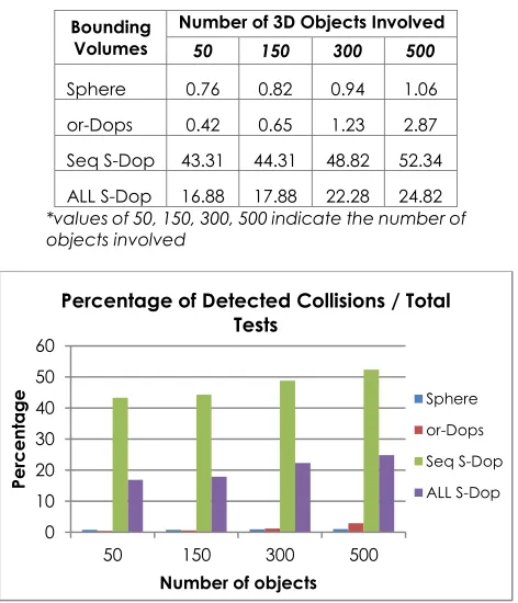
The total number of collisions detected for each scenario (50, 150, 350 and 500 objects) as compared to total number of tests involved were recorded for sphere bounding volume, or-Dops, sequential S-Dop collision culling and the batch processing version of the S-Dop collision culling method. Percentage of detected collision over total number of testing is shown in Table I, and Figure 14. In all experiments, sequential S-Dopcollision culling shows the highest percentage. This indicates that most of the tests are useful tests that lead most detected collisions.
Table 1 Percentage of collisions detected (/total number of tests) – rounded to the second decimal
Bounding Volumes
Number of 3D Objects Involved
50 150 300 500
Sphere 0.76 0.82 0.94 1.06
or-Dops 0.42 0.65 1.23 2.87
Seq S-Dop 43.31 44.31 48.82 52.34
ALL S-Dop 16.88 17.88 22.28 24.82
*values of 50, 150, 300, 500 indicate the number of objects involved
Figure 14 Fps performances for different BV
7.0 CONCLUSION
Results from the experiments showed that sphere encapsulated or-Dops(S-Dop) collision culling method offers the advantage for a better collision culling technique in a multiple rigid body simulation
compared to the homogeneous bounding volumes. This is further supported by the test conducted on a relatively crowded environment. There is also an option where it can be implemented for higher frame rates by implementation on object-of-interest if there is a need for a fast-approximate collision culling.
Acknowledgement
We would like to express our special thanks to Universiti Teknologi Malaysia (UTM) and Ministry of Higher Education (MOHE) for related support and arrangements. This research was partly supported by RUG research grant 05J21.
References
[1] Avril, Q., V. Gouranton, and B. Arnaldi. 2011. Dynamic
Adaptation of Broad Phase Collision Detection Algorithms.
In International Symposium on VR Innovation, 2011.
[2] Suaib, N. M., A. Bade, and D. Mohamad. 2013. Hybrid
Collision Culling by Bounding Volumes Manipulation in
Massive Rigid Body Simulation. TELKOMNIKA Indonesian
Journal of Electrical Engineering. 11: 3115-3122.
[3] Weller, R. 2013. New Geometric Data Structures for Collision
Detection and Haptics.
[4] Liu, F., T. Harada, Y. Lee, and Y. J. Kim. 2010. Real-time
Collision Culling of a Million Bodies on Graphics Processing
Units. ACM Trans. Graph. 29: 1-8.
[5] Bade, A., N. M. Suaib, M. Z. A, and T. S. T. M. 2006. Oriented
Convex Polyhedra for Collision Detection in 3D Computer
Animation. Proceedings of the 4th international
conference on Computer graphics and interactive
techniques in Australasia and Southeast Asia. Kuala
Lumpur, Malaysia.
[6] Sagardia, M. and T. Hulin. 2013. Fast and Accurate
Distance, Penetration, and Collision Queries Using
Point-Sphere Trees and Distance Fields. ACM SIGGRAPH 2013
Posters. Anaheim, California.
[7] Suaib, N. M., A. Bade, and D. Mohamad. 2009. Collision
Detection: A Survey of Techniques and Application. Collision Detection For Real-Time Graphics: Series of
Techniques. 1, A. Bade and N. M. Suaib, Eds. ed Johor:
Penerbit UTM, 2009.
[8] Tracy, D. J., S. R. Buss, and B. M. Woods. 2009. Efficient
Large-Scale Sweep and Prune Methods with AABB Insertion
and Removal. Proceedings of the 2009 IEEE Virtual Reality
Conference, 2009.
[9] Vogiannou, A., K. Moustakas, D. Tzovaras, and M. G.
Strintzis. 2010. Enhancing Bounding Volumes using Support
Plane Mappings for Collision Detection. Computer
Graphics Forum. 29: 1595-1604.
[10] Hubbard, P. M. 1995. Collision Detection for Interactive
Graphics Applications. Visualization and Computer
Graphics, IEEE Transactions on. 1: 218-230.
0 10 20 30 40 50 60
50 150 300 500
Per
ce
nt
a
g
e
Number of objects
Percentage of Detected Collisions / Total Tests