5001T01A
"TOUCH-A-MATIC*"
TELEPHONE SET, S SERIES
IDENTIFICATION,
INSTALLATION, CONNECTIONS,
OPERATION,
AND MAINTENANCE
1. GENERAL • Eliminate Fig. 5
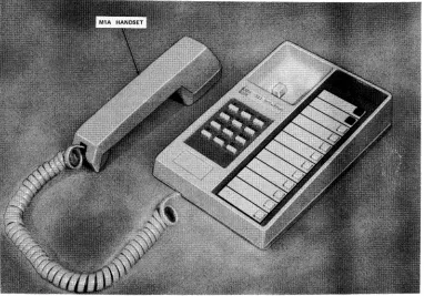
1.01 This section contains information on the • Show 500IT01A-51 and 5001T01A-58 manu-TOUCH-A-MATIC telephone S series, 12- facture discontinued (MD)(Table A) button, desk-type set (Fig. 1 and 2).
• Add emergency symbols (Fig. 2). S Warning: This equipment generates,
uses, and van radiate radio frequency i.03 This telephone set can only be used for
indi-energy and if not installed and used in vidual or single line TOUCH-TONEr service.
accordance with the instructions manual,
may cause interference to radio eommu- Note: This set is not designed for
speaker-nieations. It has been tested and found to phone, loudspeaker, A lead control, or
party-comply with the limits for a CIass B corn- line service.
puting device pursuant to Subpart J of
Part 15 of Federal Communications Corn- 1.04 This set is available in colors listed in Table A.
mission (FCC) Rules, which are designed The only faceplate color available for the
auto-to provide reasonable protection against matic dialer is silver (-122).
such interference when operated in a
commercial environment. Operation of 2. IDENTIFICATION
this equipment in a residential area is
likely tocauseinterfereneein which ease 2.01 The 5001T01A desk telephone set has a
12-the user at their own expense will be re- button automatic dialing feature. The two top
quired to take whatever measures may name and number buttons are illuminated red and
be required to correct the interference._ green by light-emitting diodes (LEDs). The set also contains a TOUCH-TONES telephone dial, tone
ring-1.02 The reasons for reissuing this section are er, and M1A handset. listed below. Revision arrows are used to
em-phasize the more signifiant changes, 2.02 Design features are as follows: • Include electromagnetic interference warn- • Modular unit.
ing notice in compliance with the FCC ruling
which requires that a warning statement be • Solid-state circuit memory and network. placed in the user documentation for
equip-ment that generates and uses radio fre- • Automatic dialing of 12 stored numbers. quency energy and may radiate that energy,
paragraph 1.01 • Will store up to 16 digits per number.
• Add information on M2A handset • Capability to record, change, or delete num-bers in memory.
• Revise battery replacement information on
instruction label (Fig. 4) t Registered Service Mark of AT&TCo.
• Registered Trademark of AT&TCo. $ Trademark of AT&TCo.
NOTICE
Fig. 1-- 5001T01A Telephone Set
• Single button dialing and directory space for • Telephone number recording with handset
names and numbers, on- or off-hook. Off-hook recording does not
interfere with conversation. • Two illuminated buttons to highlight
impor-tant numbers. • RECORD ON/OFF button protected during
normal usage by faceplate to prevent
inad-• M1A handset, vertent erasure of stored numbers.
• Electronic tone ringer. • Built in polarity guard.
• Internal S1 sounder unit which provides 2.03 Operating features are as follows: tones for automatic dialing, indicating
proper recording procedures, and for check- _ This set is not compatible with all
ingbattery. _ network facilities due to limited
available loop current, and may not
• Battery powered repertory dialer, function properly in all cases. When
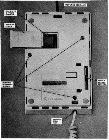
Fig. 2mI_5001T01A Telephone Set With Handset, Dialer Faceplate, Directory Sheet, and Battery, Renloved_l
loop carrier systems (SLC-1 and the record mode, subsequent operation
ter-SLC-8 type) and long Ioops (over minates the record mode.
1300 ohms), the sets may not dial
from the manual dial key pad. When • Approximately 1 to 1-1/2 minute automatic
this incompatibility is encountered, time-out if left idle in the record mode.
the customer should be directed to
exchange the set for another prod- • Approximately 10 second light time-out on the red and green LED illuminated
auto-uct. matic dial buttons.
• 12-button memory field with low force, short • Normal telephone usage with either the
auto-travel nonlocking buttons, matic dialer or manual TOUCH-TONE
tele-phone dial. • TOUCH-TONE dialing with short travel
but-tons. • Tone ringer with slide adjustment for volume
control. • RECORD ON/OFF button (under faceplate)
(a) The 5001T01A is a modular type telephone set • Cord, Handset, H4DU-(see Table A for color
and may be ordered as follows: or comcode number)
(1) Set, Telephone, 5001T01A-(see Table A for • Faceplate, 1200A1-122 color or comcode number) includes the
fol-lowing: • 841408289 Card Retainer
(a) Faceplate, 1200A1-122 • 841408255 Number Card
(b) Battery, KS-21618L2 (9-volt) • 841396559 Directory Sheet (double-sided)
(c) Handset, M1A-(see Table A for color or
comcode number) • Battery cover (see Table A for color or
comcode number)
(d) 841386352 Directory Marker (color dots
and emergency symbols) (d) 0Associated apparatus is as follows:
(e) 841396559 Directory Sheet (double-sided) (1) Handset, M2A-(see Table A for color or comcode number) (for use with inductive (f) Customer Instruction Booklet, CIB-2506. pickup hearing aids, refer to Section
501-210-110)._ (b) Order the following separately:
3. INSTALLATIONAND CONNECTIONS
(1) Cord, Mounting, D4BU-29
Note: Inside wire need not be connected to (2) Cord, Handset, H4DU-(see Table A for the ground terminal at the protector or
equiva-color or comcode number), lent.
(c) Replacement components are as follows:
3.01 Assure that the central office (CO) line is ter-• Alkaline Battery, 9-volt (customer replace- minated into a connecting block that will
ac-ment only) cept a modular D4BU mounting cord.
• Handset, M1A-(see Table A for color or 3.02 The telephone set is shipped with a 9-volt
al-comcode number) kaline battery which is to be connected at the
time of installation. Remove the battery cover
lo-• Cord, Mounting, D4BU-29 cated on the bottom of the telephone set and make
$ TABLEA 41
TELEPHONESETHOUSING, HANDSET CORD, BATTERYCOVER, AND FACEPLATECOLORS
HOUSING,HANDSET HOUSINGAND
CORD,ANDBATTERY ,HANDSETCORD, BATTERYCOVER FACEPLATESUFFIX
COVERCOLOR SUFFIX NUMBERS COLOR
Ivory -50 841411507
Green -51(MD) 841411515
Yellow -56 841411523
Silver -122
White -58 (MD) 841411531
Brown -104 841411549
the necessary connections (Fig. 3). Place the battery • To automatically dial prerecorded numbers. in the battery compartment and replace the cover.
A. To Place a Number Into Memory
Note: The battery should last approximately
one year under normal telephone usage. All sub- 4.02 Perform the following operations in sequence. sequent batteries are to be provided and
in-stalled by the customer. If service is (1) Remove the dialer faceplate by inserting fin-disconnected, remove and discard the battery, gernail into slot at top of faceplate, pull down
slightly, and lift out. 3.03 Plug one end of the mounting cord (D4BU)
into the modular jack in the rear of the set and (2) Remove the directory sheet and write or type the other end into the 625-type modular connecting the desired name(s) and telephone number(s). block. Connect the handset cord to the set (Fig. 3).
(3) Momentarily depress the RECORD ON/OFF
INSTALLATIONTEST button (Fig. 2). (A constant tone will be
heard.)
A. Telephone Set
(4) Momentarily depress the memory button ad-(1) Dial the appropriate code for ringback to jacent to the desired name listed on the
direc-test the telephone set tone ringer. Move the tory sheet. (A double interrupt of the tone will be ringer volume control lever (Fig. 3) on the bot- heard.)
tom of the set to check variation of volume.
There is no provision for ringer cutoff using the (5) Manually dial the desired number using the
volume control, digit designations to the right of the memory
buttons on the dialer. (The tone will interrupt (2) Call the CO dial test line, when connected momentarily as each digit is recorded.) The
man-press the dial buttons in sequence 1 through ual dial key pad cannot be used to record a num-9, *, 0, and # verifying that correct signals is re- ber into memory. A total of 16 digits can be
turned from the CO. recorded. When the sixteenth digit is recorded, the
B. Automatic Dialer dialer will beep three (3) times and automatically
end the recording procedure. If the dialer is
inad-(1) Record digits 1 through 9, *, 0, and # into vertently left in the record mode it will time out after 1-1/2 minutes, give three (3) beeps, and
auto-first memory location, matically reset.
(2) From the telephone set manually dial CO
"dial test circuit." (6) Momentarily depress the RECORD ON/OFF
BUTTON. [The tone will cease and the dialer
(3) When test line is Connected, depress the will be ready either for automatic dialing or to re-first memory button and verify that correct cord another telephone number into memory.
Re-signal is returned from the CO. peat Steps (3) through (6)].
(4) Repeat Steps (1), (2), and (3) for memory (7) Replace the faceplate after all numbers have
buttons two through twelve, been recorded.
4. OPERATION Note: The two top name and digit buttons are
illuminated by red and greens LEDs. Both but-4.01 The memory location buttons are used for the tons are illuminated for approximately 10
sec-following functions: onds when the handset is taken off-hook. This
enables the user to identify important numbers • To select memory locations such as police, fire, etc, especially in the dark.
Other important numbers may be highlighted • To be used as specific digits when recording by use of the adhesive backed color dots
B. To Change a Number in Memory (1) Lift the handset and listen for dial tone.
4.03 When a new number is recorded in a
previ-ously used memory position, it will automati- (2) Depress the desired memory button on the
cally replace the previously stored number, dialer.
C. To Delete a Number From Memory 5. MAINTENANCE
4.04 Perform the following operations in sequence.
(1) Remove the dialer faceplate by inserting fin- 5.01 Maintenance is limited to replacement of gernail into slot at top of faceplate, pull down mounting cord, faceplate, directory sheet,
bat-slightly, and lift out. tery cover, handset cord, and handset.
(2) Momentarily depress the RECORD ON/OFF Note: Only the M1A $or M2A0 handset can
button, be used with this telephone set.
(3) Depress the memory button corresponding to
the name and number to be deleted. Caution: Numbers stored in memory
may be erased if battery is disconnected
(4) Momentarily depress the RECORD ON/OFF for Ionger than 1 minute during
replace-button, ment.
(5) Remove the persons name and number
previ-ously written or typed on the directory sheet. 5.02 The battery is to be replaced by the customer. Refer to instruction label (Fig. 4) or Customer
(6) Replace the faceplate. Instruction Booklet (CIB-2506) for detailed testing
and replacement procedures.
D. To Automatically Dial a Number FromMemory
4.05 Perform the following to automatically dial a 5.03 If a weak or dead battery is suspected, inform
OI,LE I I I ECORO
INSTRUCTIONS ON/OFF BUTTONTO RECORD REC_D
_ITE NAMEA_ NUNBERON ON/OFF
DIRECTLY S_ET A_ PRESSIN
SEQUENCE |_NA_BUTTO_GIIDIGIT--BUTTONS
1. "ON/OFF" BUTTON (THE ON)
2. NAMEBUTTON •v
(THE BRIEFLY INTERRUPTEDTWICE)
3. DIGITS OF TELEP_NE NUMBER II 1 USI_ DIGIT BUTTO_ ON DIALER I I
(THE INTERRUPTEDMILE BUTTON
DE_ESSED)
4."ON/OFF"BUTTON(TO_ STOPS) __ A TO CALL
1. LISTEN FORDIAL TONE
2. PRESSDESIREDN_EBUTTON _----_O_
TO CHANGE A NUMBER _
1. CHA_E ENTRYON THE DIRECTLY
2. RECORDTHENEWN_ER
TO REMOVE A NUMBER
ERASEENTRYFR=THEDIRECT_Y_--_J_ SHEETA_ _ESS IN SEQUE_E 1. "H/OFF" BUTTON 2. NAMEBUTTON
3. "ON/OFF" BUTTON N AND
BATTERY CHECK DIGIT
PRESS A N_E BUTTON THAT MS A BUTTONS RECEDED P_NE N_ER.
IFYOUHE_THEDIALER"BEEP" _P_
T_ BATTERYIS GOOD. IF YOU DO _T HEM THE DIALER "DEEP", REPLACETHE BATTERY
BATTERY REPLACEMENT _ T_
DESK SETS A_ ADJUNCTSETS BEGIN WITH STEP 2
1. WALLSETS.STFIRSTBERE_VED FR_ WALLBY _--_W;
PUSHI_ UP THENPULLINGSET AWAYFR_ WALL.TO REPLACE: ALIGNSET WITHWALL_UNT
THENPUSH_ TOSECURE II 0
2. USE A 9-VOLT ALKALINEBATTERY I I 3. T_N SET OVERANDRE_VE
BATTERYFR_ COVEREDWELL
4. U_P OLDBATTERY(_Y _
WILL BE PRESERVEDF_ A I !
S_T PERIODOF TI_ MEN
BATTERYIS DISCONNECTED)
5. I_ERT NEWBATTERYINTO WELL r-'----I
FOR_E DETAILEDINF_TION CO_ERNI_ I_TALLATION,
OPERATION_ TROUBLECO_ULT YO_ I_TRUCTION BOOKLET