1
ASSESSMENT OF SIMPLIFIED TUBE SHEET ANALYSIS BASED ON
THREE DIMENSIONAL FINITE ELEMENT SIMULATION
Kulbir Singh, S. Jalaldeen, P. Chellapandi, S. C. Chetal
Nuclear Engineering Group, Indira Gandhi Centre for Atomic Research, Kalpakkam, INDIA-603102 E-mail of corresponding author: [email protected]
ABSTRACT
Tube sheets are one of the major components of a shell and tube exchanger from structural and cost point of view. The most common procedure for analyzing the stresses in perforated plates is based on treating the perforated material as an equivalent solid material with modified elastic constants. Simplified analysis with equivalent solid plate methodology is generally done by considering 2-D axisymmetric model. This simplified tube sheet analysis approach is used and compared with three dimensional finite element simulation. Two different material models viz. isotropic and anisotropic are considered to do the simplified equivalent solid plate analysis. Value of deflection in the tube sheet, membrane stress and membrane plus bending stress intensity are taken to compare the results from different analysis methods. Significance of an effect of axial stress component and pressure inside the holes of the tube sheet is highlighted for calculation of primary membrane plus bending stress intensity against the RCC-MR (A-17) procedure to calculate the same.
INTRODUCTION
Steam generator (SG) is one of the most important components of the power plant. The main function of SG in context with prototype fast breeder reactor (PFBR) is to extract the reactor heat from secondary sodium and convert the feed water into superheated steam for the turbine. The very high reactivity of sodium with water makes the SG a key component in determining the efficient running of the nuclear plant and demand high integrity of SG components. Also in sodium cooled fast reactors (SFRs) thermal shocks are more due to presence of highly conductive sodium. Tubes in SG are arranged in triangular pitch. Schematic of PFBR’s SG is shown in Fig. 1.The importance of SG as discussed above in context with SFRs demands for elaborate & optimum design of each component and tube sheet is one of the most important components of the SG from functionality, manufacturing and cost point of view.
SG has two tube sheets i) steam side (top) tube sheet ii) water side (bottom) tube sheet. These tube sheets have 547 holes in which SG tubes are fixed and welded, water flows through the tubes and sodium is on shell side of SG. Water is entering at pressure (~19 MPa) in SG and the presence of thermal loading during different transients complicates the design of tube sheet.
Water side tube sheet of PFBR’s SG is taken to carry out the study on perforated plates. General case of loading and geometry is taken for present study of tube sheet. Tube sheet is analyzed for pressure loading at room temperature without considering thermal loads and transients.
The general procedure for analyzing the stresses in perforated plates is based on treating the perforated material as an equivalent solid material with modified elastic constants [1]. These constants, referred to as the effective elastic constants, are determined from the requirement that gross deformation in the perforated material and the equivalent solid material be the same under the same loading conditions. In general equivalent solid plate methodology fails to give 1) Stress distribution in non uniform diameter holes, 2) Realistic stresses at interface of perforated and solid region, 3) Pressure effect inside the holes of perforated plate, 4) Effect of temperature
2
dependent properties in perforated region. In RCC-MR appendix A-17, equivalent solid plate methodology is given for doing analysis of tube sheets with holes arranged in equilateral triangular or constant circular pitch with uniform diameter [2].
GEOMETRICAL DETAILS, LOADING AND PROPERTIES
Geometry of water side tube sheet of PFBR’s SG is taken for the purpose of analysis. Water side tube sheet of SG have thickness 150 mm with 547 holes arranged in equilateral triangular pattern with pitch value 32.2 mm. Orifice holes diameter of 17.5 mm is taken for analysis with last hole at 790.5 mm pitch circle diameter. Shell diameter (outer) of SG is 1237 mm with thickness 30 mm. Head diameter (outer) is 1090 mm and head diameter (inner) is 910 mm.
The tube sheet under consideration is subjected to feed water inlet pressure of 19 MPa from one side (bottom side of tube sheet) and on another side, tube sheet is seeing sodium with pressure 0.4 MPa. Net pressure applied on the tube sheet is 18.6 MPa from bottom side of tube sheet in upward direction. For schematic, geometrical details and loading see Fig.2.
Properties [3] used to do the analysis of tube sheet are density (7753 kg/m3), young’s modulus (213 GPa), coefficient of thermal expansion (10.5 x 10⁻⁶ m/m.°C), poison’s ratio (0.3).
EQUIVALENT SOLID PLATE METHOD AS PER RCC-MR (A-17) CONSIDERING ISOTROPIC MATERIAL MODEL
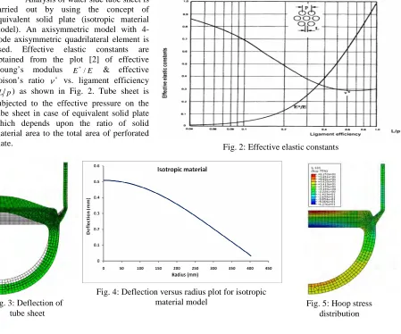
Analysis of water side tube sheet is carried out by using the concept of equivalent solid plate (isotropic material model). An axisymmetric model with 4-node axisymmetric quadrilateral element is used. Effective elastic constants are obtained from the plot [2] of effective Young’s modulus E /* E & effective
poison’s ratio ν* vs. ligament efficiency
(L p) as shown in Fig. 2. Tube sheet is subjected to the effective pressure on the tube sheet in case of equivalent solid plate which depends upon the ratio of solid material area to the total area of perforated
plate. Fig. 2: Effective elastic constants
Fig. 4: Deflection versus radius plot for isotropic material model
Fig. 3: Deflection of tube sheet
3
Deflection of tube sheet under pressure loading with isotropic material model is shown in Fig. 3 and variation of deflection along with the radius of tube sheet is shown in Fig. 4. Maximum deflection occurs at center of tube sheet with value 0.509 mm. Stress distribution of each component viz. hoop, radial, axial and shear stress in the tube sheet is obtained and linearized along the critical sections (center of the tube sheet in this case) to get membrane and bending stress components. Hoop stress distribution is shown in Fig. 5. Stress calculated using FEA is equivalent solid plate (ESP) stresses as the analysis is carried out by assuming the perforated plate as a solid plate. In the perforated region of the tube sheet, the ESP membrane stress are transformed into values representing the average stress through the width of minimum ligament by multiplying ESP stress by inverse of ligament efficiency. In case of axial stress ratio of E/ E* is used to get the true stress from ESP stress value.
Simplified approach of equivalent solid plate methodology cannot assess the membrane stresses in the ligament due to pressure loading
within the perforations in finite element model. This additional stress is calculated separately and combined with the component stress due to pressure loading. Value of membrane stress component and membrane plus bending stress component for an isotropic material are given in Table-1.
EQUIVALENT SOLID PLATE MODEL AS PER RCC-MR (A-17) CONSIDERING ANISOTROPIC MATERIAL MODEL
At higher thickness values it is desirable to consider anisotropic material model having different young’s modulus in thickness direction. The effective elastic constants are isotropic in plane of the plate but have different effective elastic constants along the thickness direction.
Effective pressure & in-plane properties of equivalent solid plate are same as in isotropic material model. In thickness direction different set of elastic constants is considered to account an anisotropic behavior [4, 5]. An effective Young’s modulus E′
in thickness is equal to true Young’s modulus E reduced by the ratio of solid material area to the total area and effective poison’s ratio in the thickness direction is equal to the Poisson’s ratio of solid material (ν′=ν)
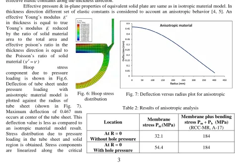
Hoop stress component due to pressure loading is shown in Fig.6. Deflection of tube sheet under pressure loading with anisotropic material model is plotted against the radius of tube sheet (shown in Fig. 7). Maximum deflection of 0.467 mm occurs at center of the tube sheet. This deflection value is less as compared to an isotropic material model result. Stress distribution due to pressure loading in the tube sheet and solid region is obtained. Stress components are linearized along the critical
Table1: Results of isotropic analysis
Location Membrane stress Pm (MPa)
Membrane plus bending stress Pm + Pb (MPa)
(RCC-MR, A-17)
At R = 0
Without hole pressure 37.9 185.4 At R = 0
With hole pressure 59.1 185.4
Table 2: Results of anisotropic analysis
Location Membrane stress Pm (MPa)
Membrane plus bending stress Pm + Pb (MPa)
(RCC-MR, A-17)
At R = 0
Without hole pressure 32.1 184
At R = 0
With hole pressure 54.4 184
Fig. 7: Deflection versus radius plot for anisotropic material model
4
sections to get membrane and bending stress components. Value of membrane stress component and membrane plus bending stress component for an anisotropic material are given in Table 2.
THREE DIMENSIONAL ANALYSIS OF TUBE SHEET
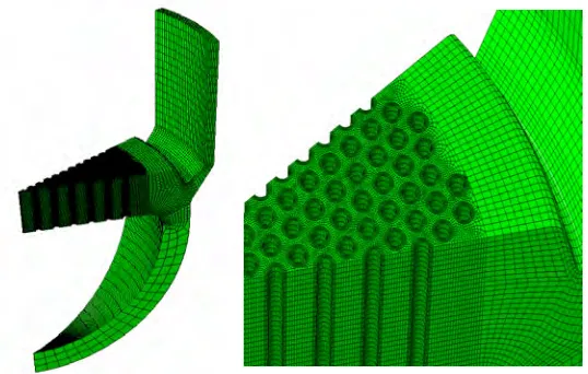
To assess the equivalent solid plate methodology using isotropic and anisotropic material model, three dimensional analysis of tube sheet with actual geometry and properties is carried out. Also due to drawbacks of the equivalent solid plate methodology mentioned earlier the three dimensional model of tube sheet is analyzed for pressure loading. Symmetry exists in 30° sector of tube sheet in terms of geometry, load and constraints for tube sheet. Hence FEA problem is reduced to 30° sector model, meshed model is shown in Fig.8. Total number of elements in the model is 336540.
Deflection of tube sheet for two cases viz. without pressure inside holes and with pressure inside holes as a function of radius is shown in Fig. 9 with maximum deflection of 0.472 mm (without pressure inside holes) and 0.491 (with pressure inside holes) at center of the tube sheet. Three dimensional stress distributions for each component of stress viz. radial, axial, hoop and shear stress in tube sheet due to pressure loading is obtained from analysis results. Radial and hoop stress components are shown in Fig. 10 & 11. It can be noted from stress distributions that there is peak stress distribution along the periphery of the holes which cannot be directly obtained from equivalent solid plate methodology.
Note: - Results shown for the three dimensional analysis are for the case in
which pressure is applied inside the holes of the tube sheet. Similar procedure is followed for the cases when pressure is not applied in the tube sheet.
Linearization of stress components in equivalent solid plate methodology is carried out by using line integral, as critical section can be defined by the line along the thickness. But in three dimensional analysis critical section is defined by surface which represents the minimum ligament surface called stress classification plane (SCP) [6, 7,
8]. In single SCP multiple stress classification lines can be defined. In this case of perforated plate, critical SCP is selected at the ligament which is the plane with minimum distance between the holes of perforated plate and closest
Table 3: Results of three dimensional analysis
Location Membrane stress Pm (MPa)
Membrane plus bending stress Pm + Pb (MPa)
(RCC-MR, A-17)
At central ligament
(Without hole pressure) 32.4 194.3 At central ligament
(With hole pressure) 47.2 212.2
Fig. 9: Deflection versus radius plot for three dimensional model Fig. 8: Three dimensional meshing of tube sheet along
5
to the center of the plate as shown in Fig. 14. Stress variation along the width and height of SCP for radial and hoop stress component is shown in Fig.12 & 13. Summary of the results with three dimensional analysis for both cases viz. without pressure inside the holes and with pressure inside the holes of the tube sheet are shown in Table 3.
COMPARISON OF EQUIVALENT SOLID PLATE MODELS AND THREE DIMENSIONAL ANALYSIS
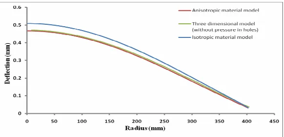
Deflection of tube sheet for all cases without pressure inside the holes of the tube sheet is shown in Fig. 14. Deflection of tube sheet with an anisotropic material model is matching with three dimensional analysis deflection values. Isotropic model deflection value is higher as compared to other two modeling methods.
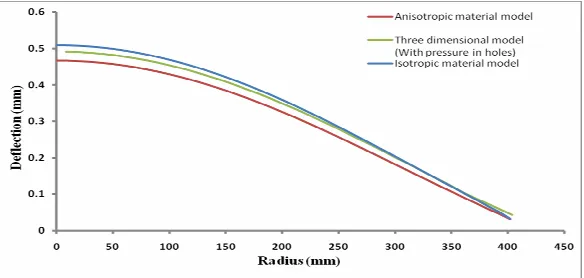
Deflection of tube sheet with respect to radius with pressure inside the holes of the tube sheet is shown in Fig. 15. Deflection is
Fig. 13: Hoop stress distribution at critical ligament along the SCP Fig. 12: Radial stress distribution at
critical ligament along the SCP
Fig. 14: Deflection vs. radius for all cases (Without pressure in holes) Fig. 11: Hoop stress distribution in tube
sheet due to pressure Fig. 10: Radial stress distribution in tube
6
highest for isotropic material model, lowest for anisotropic material model and for three dimensional analysis it lies in between the two. Deflection of three dimensional analysis result is increased with pressure inside holes as compared to the case without pressure inside the holes of tube sheet.
Primary membrane and primary membrane plus bending stress intensities calculated using equivalent solid plate methodology and three dimensional model, are compared for following two cases:
Without Pressure in Holes of Tube Sheet
From the Table 4 in case membrane stress component in the tube sheet for anisotropic analysis is matching with three dimensional analysis, whereas isotropic analysis gives conservative value. Primary membrane plus bending stress calculated as per RCC-MR, Appendix A-17 gives lower value as compared to three dimensional analysis.
With Pressure in Holes of Tube Sheet
From the Table 5, membrane stress component in the tube sheet for anisotropic analysis is close with three dimensional analysis, whereas isotropic analysis gives higher value as compared anisotropic analysis. Primary membrane plus bending stress calculated as per RCC-MR, Appendix A-17 ignores the effect of pressure inside holes of tube sheet and
gives lower value as compared to three dimensional analysis.
Due to inconsistency in the results of primary membrane plus bending stress intensity as per RCC-MR (A-17) with three dimensional analysis, modification is suggested in RCC-MR (A-(A-17) calculation procedure.
MODIFICATION IN RCC-MR (A-17) RULES TO CALCULATE PRIMARY MEMBRANE PLUS BENDING STRESS IN TUBE SHEETS
RCC-MR (Appendix A-17) uses maximum value of radial or circumferential stress to find the primary membrane plus bending stress intensity [2]. Contribution of axial stress value is neglected to find the primary membrane plus bending stress intensity, also pressure inside the holes of the tube sheet is not contributing in the final stress values.
Equivalent solid plate analysis as per RCC-MR (A-17) is carried out without applying pressure inside holes of the tube sheet. Procedure to calculate membrane stress includes effect of stress due to pressure inside hole. In case of primary membrane plus bending stress component maximum of radial or circumferential (equivalent solid plate) stress is used in RCC-MR (A-17). Total linearized stress components calculated in radial and circumferential direction are used to find the biaxiality ratio stress multiplier only.
Table 4: Comparison - without pressure in holes of tube sheet (stresses in MPa)
Stress Type Isotropic analysis
Anisotropic analysis
Three dimensional analysis Pm 37.9 32.1 32.4 Pm + Pb
(RCC-MR, A-17) 185.4 184 194.3
Table 5: Comparison - with pressure in holes of tube sheet (stresses in MPa)
Stress Type Isotropic analysis
Anisotropic analysis
Three dimensional analysis Pm 59.1 54.4 47.2 Pm + Pb
RCC-MR, A-17 185.4 184 212.2
7
It is proposed to find the primary membrane plus bending stress from component stresses. With this approach effect of axial stress is included and also stress inside tube sheet due pressure in holes is added. These stress components are used to find principal stresses and finally primary membrane plus bending stress intensity.
Summary of Results after Modification in RCC-MR (A-17)
Calculation of primary membrane plus bending stress without pressure inside holes using component wise linearized stress is in good agreement with three dimensional analysis (shown in Table 6).
Primary membrane plus bending stress calculated as per RCC-MR, Appendix A-17 ignores the effect of pressure inside holes of perforated plate and gives lower value as compared to three dimensional analysis. Effect of axial stress component as discussed above also effects the results. Use of component wise stresses
with pressure inside holes leads to the result which are in good agreement with three dimensional analysis (shown in Table 7).
SUMMARY
Simplified tube sheet analysis using equivalent solid plate methodology (isotropic & anisotropic) is assessed with three dimensional finite element simulation. Deflection of the tube sheet for different radius values for all the analysis methods is compared by considering no pressure inside holes & with pressure inside holes of tube sheet. Stress intensities values at the center of the tube sheet are compared for different models.
Deflection of tube sheet with anisotropic material model is very close to three dimensional model with no pressure inside the holes. Isotropic analysis gives higher value of deflection as compared to three dimensional model.
Primary membrane stress value as per RCC-MR (A-17) in case of anisotropic material model is in good agreement with three dimensional results, whereas isotropic material model gives conservative value.
Primary membrane plus bending stress as per RCC-MR (A-17) is lower as compared to three dimensional results, but with minor modification suggested in calculation procedure for RCC-MR (A-17), rules can be applied for tube sheet analysis to get results in good agreement with three dimensional results.
In case of analysis with pressure inside holes of the tube sheet equivalent solid plate methodology gives conservative results for both isotropic and anisotropic models.
Proposed method for calculation of primary membrane plus bending stress is used and found to be in good agreement with three dimensional results.
REFERENCES
[1] Ukadgaonkar. V.G. et. al. “Review of analysis of tube sheets” International journal of pressure vessels and
piping. Volume 67, Issue 3, August 1996, pp. 279-297.
[2] Design and construction rules for mechanical components of nuclear installations (RCC-MR - 2007), Section 1 Subsection Z, Appendix A-17, “Design of flat tube plates”.
Table 6: Comparison with modified procedure - without pressure in holes of tube sheet (stresses in MPa)
Stress Type Isotropic analysis
Anisotropic analysis
Three dimensional analysis Pm 37.9 32.1 32.4
RCC-MR, A-17 185.4 184
Pm + Pb
Modified procedure 200.7 193.2
194.3
Table 7: Comparison with modified procedure - with pressure in holes of tube sheet (stresses in MPa)
Stress Type Isotropic analysis
Anisotropic analysis
Three dimensional analysis Pm 59.1 54.4 47.2 RCC-MR, A-17 185.4 184
Pm + Pb
8
[3] Design and construction rules for mechanical components of nuclear installations (RCC-MR - 2007), Section 1 Subsection Z, Appendix A-3 “Characteristics of materials”.
[4] O’Donnell. W.J. “Perforated plates and shells”. Pressure vessels and piping: Design and analysis: Decade
of progress - Volume II, Chapter 4.
[5] Srinivasan. R. et. al. “Structural mechanics analysis of intermediate heat exchanger for prototype fast breeder reactor”. Transactions of the 17th international conference on structural mechanics in reactor technology (SMIRT-17)”. 17-22 August 2003, Prague, Czech Republic.
[6] Rao. K.R. Companion guide to the ASME boiler and pressure vessel code, Volume-1.
[7] Woo-Seok Choi. et. al. “Shape optimization of a perforated pressure vessel cover under linearized stress constraints”. Nuclear Engineering and Design, 238 (2008). pp. 2468-2472