User Manual
Part Number
T-Watch is a trademark of ADTRAN, Inc. OpenViewR
901 Explorer Boulevard P.O. Box 140000 Huntsville, AL 35814-4000
Phone: (256) 963-8000
© 2001 ADTRAN, Inc. All rights reserved.
Important Safety Instructions
When using your telephone equipment, please follow these basic safety precau-tions to reduce the risk of fire, electrical shock, or personal injury:
1. Do not use this product near water, such as near a bathtub, wash bowl, kitchen sink, laundry tub, in a wet basement, or near a swimming pool. 2. Avoid using a telephone (other than a cordless-type) during an electrical
storm. There is a remote risk of shock from lightning.
3. Do not use the telephone to report a gas leak in the vicinity of the leak. 4. Use only the power cord, power supply, and/or batteries indicated in the
manual. Do not dispose of batteries in a fire. They may explode. Check with local codes for special disposal instructions.
Notes provide additional useful information.
Cautions signify information that could prevent service interruption.
1. This equipment complies with Part 68 of the FCC rules. The required label is attached to the bottom of the chassis.
2. An FCC compliant telephone cord and modular plug is provided with this equipment. This equipment is designed to be connected to the telephone net-work or premises wiring using a compatible modular jack which is Part 68 compliant. See installation instructions for details.
3. If your TDU 120e causes harm to the telephone network, the Telephone Com-pany may discontinue your service temporarily. If possible, they will notify you in advance. If advance notice is not practical, you will be notified as soon as possible. You will be advised of your right to file a complaint with the FCC. 4. Your telephone company may make changes in its facilities, equipment,
oper-ations, or procedures that could affect the proper operation of your equip-ment. If they do, you will be given advance notice so as to give you an opportunity to maintain uninterrupted service.
5. If you experience trouble with the equipment TDU 120e, please contact ADT-RAN at (256) 963-8000 for repair/warranty information. The telephone com-pany may ask you to disconnect this equipment from the network until the problem has been corrected, or until you are sure the equipment is not mal-functioning.
6. This unit contains no user serviceable parts.
7. The following information may be required when applying to your local tele-phone company for leased line facilities.
8. The FCC recommends that the AC outlet to which equipment requiring AC power is to be installed is provided with an AC surge arrester.
Service Type REN/SOC FIC USOC
tal terminal equipment without encoded analog content and billing protec-tion is used to transmit digital signals containing encoded analog content which are intended for eventual conversion into voice band analog signal and transmitted on the network.
• The affidavit shall affirm that either no encoded analog content or billing information is being transmitted or that the output of the device meets Part 68 encoded analog content or billing protection specification.
• End use/customer will be responsible to file an affidavit with the local exchange carrier when connecting unprotected CPE to a 1.544 Mbps or sub-rate digital service.
For the work to be performed in the certified territory of ______________ (telco name)
State of ________________________________
County of ______________________________
I, _______________________ (name), ____________________ (business address), _____________________ (telephone number) being duly sworn, state:
I have the responsibility for the operation and maintenance of the terminal equip-ment to be connected to 1.544 Mbps and/or __________________ subrate digital services. The terminal equipment to be connected complies with Part 68 of the FCC rules except for the encoded analog content and billing protection specifica-tion. With respect to encoded analog content and billing protection:
( ) I attest that all operations associated with the establishment, maintenance and adjustment of the digital CPE with respect to encoded analog content and billing protection information continuously complies with Part 68 of the FCC rules and Regulations.
( ) The digital CPE does not transmit digital signals containing encoded analog content or billing information which is intended to be decoded within the tele-communications network.
( ) The encoded analog content and billing protection is factory set and is not under the control of the customer.
I attest that the operator(s) maintainer(s) of the digital CPE responsible for the establishment, maintenance and adjustment of the encoded analog content and billing information has (have) been trained to perform these functions by success-fully having completed one of the following (check appropriate blocks):
( ) A. A training course provided by the manufacturer/grantee of the equipment used to encode analog signals; or
signals; or
( ) D. In lieu of the proceeding training requirements, the operator(s)/main-tainer(S) is (are) under the control of a supervisor trained in accordance with _______________ (circle one) above.
I agree to provide ____________________ (telco’s name) with proper documenta-tion to demonstrate compliance with the informadocumenta-tion in the preceding paragraph, if so requested.
_____________________ Signature
_____________________ Title
_____________________ Date
Subscribed and sworn to before me
This _________ day of ___________________, 20__
_______________________________________ Notary Public
This equipment has been tested and found to comply with the limits for a Class A digital device, pursuant to Part 15 of the FCC Rules. These limits are designed to provide reasonable protection against harmful interference when the equipment is operated in a commercial environment. This equipment generates, uses, and can radiate radio frequency energy and, if not installed and used in accordance with the instruction manual, may cause harmful interference to radio frequencies. Operation of this equipment in a residential area is likely to cause harmful inter-ference in which case the user will be required to correct the interinter-ference at his own expense.
Shielded cables must be used with this unit to ensure compliance with Class A FCC limits.
Canadian Emissions Requirements
This digital apparatus does not exceed the Class A limits for radio noise emissions from digital apparatus as set out in the interference-causing equipment standard entitled “Digital Apparatus," ICES-003 of the Department of Communications.
Cet appareil nuerique respecte les limites de bruits radioelectriques applicables aux appareils numeriques de Class A prescrites dans la norme sur le materiel brouilleur: "Appareils Numeriques," NMB-003 edictee par le ministre des Com-munications.
Notice: The Canadian Industry and Science Canada label identifies certified equipment. This certification means that the equipment meets certain telecom-munications network protective, operational, and safety requirements. The Department does not guarantee the equipment will operate to the user’s satisfac-tion.
Before installing this equipment, users should ensure that it is permissible to be connected to the facilities of the local telecommunications company. The equip-ment must also be installed using an acceptable methods of connection. In some cases, the company’s inside wiring associated with a single line individual service may be extended by means of a certified connector assembly (telephone extension cord). The customer should be aware that compliance with the above limitations may not prevent degradation of service in some situations.
Repairs to certified equipment should be made by an authorized Canadian main-tenance facility designated by the supplier. Any repairs or alterations made by the user to this equipment, or equipment malfunctions, may give the telecommunica-tions company cause to request the user to disconnect the equipment.
Users should ensure for their own protection that the electrical ground connec-tions of the power utility, telephone lines and internal metallic water pipe system, if present, are connected together. This precaution may be particularly important in rural areas.
The Load Number (LN) assigned to each terminal device denotes the percentage of the total load to be connected to a telephone loop which is used by the device, to prevent overloading. The termination on a loop may consist of any combina-tion of devices subject only to the requirement that the total of the Load Numbers of all devices does not exceed 100.
ADTRAN warrants that for five (5) years from the date of shipment to Customer, all products manufactured by ADTRAN will be free from defects in materials and workmanship. ADTRAN also warrants that products will conform to the applica-ble specifications and drawings for such products, as contained in the Product Manual or in ADTRAN's internal specifications and drawings for such products (which may or may not be reflected in the Product Manual). This warranty only applies if Customer gives ADTRAN written notice of defects during the warranty period. Upon such notice, ADTRAN will, at its option, either repair or replace the defective item. If ADTRAN is unable, in a reasonable time, to repair or replace any equipment to a condition as warranted, Customer is entitled to a full refund of the purchase price upon return of the equipment to ADTRAN. This warranty applies only to the original purchaser and is not transferable without ADTRAN's express written permission. This warranty becomes null and void if Customer modifies or alters the equipment in any way, other than as specifically authorized by ADTRAN.
EXCEPT FOR THE LIMITED WARRANTY DESCRIBED ABOVE, THE FOREGO-ING CONSTITUTES THE SOLE AND EXCLUSIVE REMEDY OF THE CUS-TOMER AND THE EXCLUSIVE LIABILITY OF ADTRAN AND IS IN LIEU OF ANY AND ALL OTHER WARRANTIES (EXPRESSED OR IMPLIED). ADTRAN SPECIFICALLY DISCLAIMS ALL OTHER WARRANTIES, INCLUDING (WITH-OUT LIMITATION), ALL WARRANTIES OF MERCHANTABILITY AND FIT-NESS FOR A PARTICULAR PURPOSE. SOME STATES DO NOT ALLOW THE EXCLUSION OF IMPLIED WARRANTIES, SO THIS EXCLUSION MAY NOT APPLY TO CUSTOMER.
shipment if the product does not meet its published specification, or if it fails while in service.
A return material authorization (RMA) is required prior to returning equipment to ADTRAN. For service, RMA requests, training, or more information, see the toll-free contact numbers given below.
Presales Inquiries and Applications Support
Please contact your local distributor, ADTRAN Applications Engineering, or ADTRAN Sales:
Post-Sale Support
Please contact your local distributor first. If your local distributor cannot help, please contact ADTRAN Technical Support and have the unit serial number avail-able.
The Custom Extended Services (ACES) program offers multiple types and levels of service plans which allow you to choose the kind of assistance you need. For questions, call the ACES Help Desk.
Applications Engineering (800) 615-1176
Sales (800) 827-0807
Technical Support (888) 4ADTRAN
port will coordinate with the Custom and Product Service (CAPS) department to issue an RMA number. For information regarding equipment currently in house or possible fees associated with repair, contact CAPS directly at the following number:
Identify the RMA number clearly on the package (below address), and return to the following address:
ADTRAN Customer and Product Service 901 Explorer Blvd.
Huntsville, Alabama 35806
RMA # _____________
Training
The Enterprise Network (EN) Technical Training offers training on our most popu-lar products. These courses include overviews on product features and functions while covering applications of ADTRAN's product lines. ADTRAN provides a vari-ety of training options, including customized training and courses taught at our fa-cilities or at your site. For more information about training, please contact your Territory Manager or the Enterprise Training Coordinator.
CAPS Department (256) 963-8722
Training - phone (800) 615-1176, ext. 7500
Training - fax (256) 963-6700
List of Figures ...1-xxi
List of Tables ... 1-xxiii
Chapter 1. Introduction...1-1 TDU 120e Overview ...1-1 Standard Features in the TDU 120e ...1-3 TDU 120e Option Modules ...1-4 DSX-1 ...1-4 Full Drop and Insert ...1-4 Nx56/64 serial interface ...1-4 Voice interface ...1-4 OCU DP ...1-4 DSU DP ...1-4 Dial backup ...1-4 U-BR1TE ...1-4 Option Module Architecture...1-5 TDU 120e Configuration Applications ...1-6 Router, PBX, Video Conferencing Application ...1-6
Network Interface ...2-6 Nx56/64 Serial Interface ...2-6 DS-1 (PBX) Interface ...2-7 Control In Port ...2-7 Craft Port ... 2-7 Control Out Port ...2-7 10BaseT Interface ...2-7 External Alarm Connector ...2-7 Power Up Testing ... 2-8 Self-Test... 2-8 Initialization ... 2-9 Set User Passcode ... 2-9 Set Unit Identification ...2-9 Set Control Port... 2-9 Chain In (PC)... 2-10 Chain In/Chain Out...2-10 Normal Power-Up Procedure ...2-11
DS1 Monitor Jack ...3-8 LEDs...3-9 Network Status LEDs ...3-9 Port Status LEDs ...3-10 Port 1.1 Option Card Monitor Jacks ...3-10 Alternate Methods of Control ...3-11 T-Watch PRO (ADTRAN PC Program)...3-11 Setting up the TDU 120e to Work over a LAN ...3-11 Setting up the TDU 120e to Work over an EIA-232 Connection ...3-12 SNMP...3-12
TX ... 4-8 RX ... 4-8 LNK ... 4-8 CPU ... 4-8
Editing the Temp Map ...5-20 Applying the Temp Map ...5-20 Copying Map ...5-20 Reviewing Maps ...5-21 Review Map A (B) ...5-22 Review Temp Map ...5-22 Edit Temp Map ...5-22 Apply Temp to Map A (B) ...5-22 Port Configuration (Port Config)...5-22 Nx/DBU (0.1) Menu Items ...5-23 Nx56/64 Config ...5-23 Dial Backup Config ...5-25 DS-1 (0.2) Menu Items ...5-28 Format ...5-28 Code ...5-28 Yellow Alarm ...5-28 Line Length (ft) ...5-28 Inband Loopback ...5-28 Robbed Bit Signaling ...5-29 RBS Start ...5-29 RBS End ...5-29
Chapter 6. Utility Menu ...6-1 Util ...6-1 Time/Date ...6-2 Factory Restore...6-2 Set Passcode...6-3 Change/Set a Passcode ...6-3 Lost Passcode ...6-3 No Passcode Desired ...6-3 Unit ID ...6-3 To Set the Unit Identification ...6-4 No Unit ID Desired ...6-4 Software Revision ...6-4 Port Utility ...6-4 MAC Address...6-4
Line ... 7-3 Payload ... 7-3 Local Loopback ...7-3 Line On ... 7-3 Payload On ... 7-3 No Loopback ... 7-4 Remote Loopback ...7-4 ATT In-Band LLB ... 7-4 ANSI FDL PLB ... 7-4 ANSI FDL LLB ... 7-4 ANSI FT1 LLB ... 7-4 No Loopback ... 7-4 Test Patterns ...7-5 All Ones ... 7-5 All Zeros ... 7-5 QRSS Pattern ... 7-5 QRSS All DS0s ... 7-5 QRSS TST DS0s ... 7-6 None ... 7-6 Instructions for Generating a QRSS Test Pattern ... 7-6 Pattern Result ... 7-6 ES ... 7-6 BES ... 7-6 SES ... 7-7 *SYNC ... 7-7 How to Run an End-to-End Test on Fractional DS0s ... 7-7 Run Self-Test ... 7-8 Port Tests ... 7-9 Nx/DBU (0.1) Menu Items ...7-9 DTE LOOPBACK ... 7-9 511 PATTRN ... 7-10 511 RESULTS ... 7-10 DBU LOOPBACK ... 7-10 DBU TEST ... 7-10 DBU DATA/CNTRL ... 7-11 DBU TST RESULT ... 7-11 DS-1 (0.2) Menu Items ...7-11 Loopback ... 7-11 Cancel Tests... 7-11
Management Configuration ...8-1 Unit Access Table ...8-2 SNMP Read Community ...8-4 SNMP Read/Write Community ...8-4 SNMP Trap Community ...8-4 Host 1 Trap IP Address ...8-4 Host 2 Trap IP Address ...8-5 Host 3 Trap IP Address ...8-5 Host 4 Trap IP Address ...8-5 System Name ...8-5 System Contact ...8-5 System Location ...8-5 Auth. Fail Traps Sent ...8-5 Poll Link Status Traps Sent ...8-5 Ping IP Host ...8-6 Telnet/Terminal Timeout ...8-6 Telnet/Terminal Password ...8-6 Exit ...8-6 Flash Download ...8-6 XMODEM ...8-6 Trivial File Transfer Protocol (TFTP) ...8-6 TFTP Server IP Address: 0.0.0.0. ...8-7 TFTP Server File name: T120e.biz ...8-7 Begin Firmware update. ...8-7 Quit Session ...8-7
Appendix A. Understanding SNMP ... A-1
Appendix B. Connector Pinouts... B-1
Appendix C. System Messages ... C-1
Appendix D. Specifications ... D-1
TDU 120e OVERVIEW
The TDU 120e is a T1/FT1 multiplexer with the following features:
• Nx56/64 V.35 data port • DS-1 (PBX) interface • option slot
• embedded SNMP management
The TDU 120e’s option slot accepts one of many available option modules for voice and data applications.
The TDU 120eserves as the link between user data sourc-es such as:
• local area network (LAN) bridges and routers • computers
• CAD systems
• teleconferencing equipment
• PBXs
recon-option modules provides a path for growth to accommo-date future requirements.
Standard Features in the TDU 120e
The following list describes the standard features in the enhanced TDU 120e.
• A single T1 interface.
• An Nx/DBU V.35 port and a DS-1 (PBX) interface. • An inband communication channel requiring only 8k
of bandwidth from a single DS0.
• One option slot to house option modules with up to four additional ports, including voice and data. • Allows mix of port types to meet the data interface
re-quirements.
• Easy configuration capabilities using simplistic menus displayed on a terminal or computer connect-ed to the control port on the rear of the unit or the craft port on front of the unit.
• Two programmable configuration maps that define the bandwidth allocation between data ports. • Data drop and insert, as well as full drop and insert. • Flash memory for software updates.
• Timing is selectable from the network, from the Nx56/64 or DS-1 ports, internally, or from a second-ary interface.
• QRSS; 511 test patterns using Nx option.
• Extensive self-testing and monitoring provides assur-ance of proper operation.
• SNMP, Telnet, and T-Watch PRO management via SLIP or 10-BaseT
• Ability to proxy for “agentless” units • Enhanced terminal mode
• Fractional T1 loopbacks as defined in Annex B of ANSI T1.403-1995
• Software configurable long-haul or short-haul DS-1 port
TDU 120e OPTION MODULES
Some of the option modules available for the TDU 120e are:
DSX-1
Provides a short haul T1 interface for operation with a PBX (Terminal Interface).
Full Drop and Insert
Permits the dropping of data and insertion of new data into the same DS0 time slot.
This module includes a long haul DS-1 interface. It can also be used as a second DS-1 interface to provide an up to 3 MB aggregate throughput.
Nx56/64 serial interface
Provides a V.35 serial interface in either single or dual versions.
Voice interface
Provides 2 or 4 channels FXS/FX0/E&M.
OCU DP
Interfaces to DDS or 4-wire Switched 56, dual or single versions.
DSU DP
Provides two sync or async ports (EIA-232 or V.35).
Dial backup
Allows for backup of data upon network T1 failure.
U-BR1TE
Option Module Architecture
The TDU 120e features a unique architecture that allows the addition of one option module and plug-on board providing an opportunity for growth to accommodate an-other application. See Figure 1-1.
Figure 1-1. TDU 120e Option Modules
DSX-1 Module Plug on V.35 Plug on OCU DP Plug on Dual Voice OCU-DP Module V.35 Module D&I Module DUAL Voice ACO REMOTE ACCESSCRAFT TDU 120eAC NETWORK MON
IN OUTIN OUTIN OUTIN OUTPORT 0.2 MON
IN OUTIN OUT PORT 1.1 MON TEST
OKYELRED ALARMERROR NETWORK STATUS TESTOK
ALARM PORT STATUS 0.10.21.11.21.31.4
TDU 120e CONFIGURATION APPLICATIONS
The following examples illustrate possible configurations of TDU 120e applications.
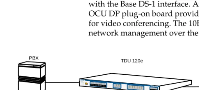
Router, PBX, Video Conferencing Application
In this application, the Base Nx/DBU provides a V.35 in-terface to a router. The PBX is inin-terfaced to the TDU 120e with the Base DS-1 interface. An OCU DP module and OCU DP plug-on board provide two switched 56 circuits for video conferencing. The 10BaseT port allows SNMP network management over the LAN. See Figure 1-2.
Figure 1-2. Bridge, PBX, Video Conferencing Application Set-up
TDU 120e PBX
VIDEO CONFERENCING
ROUTER
10 BaseT LAN
SNMP NETWORK MANAGEMENT WORKSTATION
ACO REMOTE ACCESS CRAFT
TDU 120eAC NETWORK MON
IN OUTIN OUTIN OUTIN OUT PORT 0.2 MON
IN OUTIN OUT PORT 1.1 MON TESTOK
YEL RED ALARMERROR NETWORK STATUS TEST
OK ALARM
UNPACK, INSPECT, POWER UP
Receipt Inspection
Carefully inspect the TDU 120efor any shipping damag-es. If you suspect damage, file a claim immediately with the carrier and then contact ADTRAN Customer Service (see the front section of this manual for contact informa-tion). If possible, keep the original shipping container for use in shipping the TDU 120e back for repair or for verifi-cation of damage during shipment.
ADTRAN Shipments
The following items are included in the ADTRAN ship-ment:
• The TDU 120e
• 2-line interface cables: A 15-foot, 8-position modular to 8-position modular
• A DB-25 to modular adapter
• A 6-foot, 8-position modular cable for connection to the chain-in port
Customer Provides
• Cables for any expansion modules to be used with the TDU 120e
• 10BaseT cable for connection to a LAN or router (if you plan to use remote management features)
POWER CONNECTION
AC Powered Units
Each TDU 120e AC unit is equipped with a captive eight-foot power cord, terminated by a three-prong plug which connects to a grounded power receptacle.
DC Powered Units
Each TDU 120e DC unit is provided with a two-pin power receptacle and mating plug. Power to the TDU 120e DC unit is + 48 VDC or +24 VDC.
GROUNDING INSTRUCTIONS
Grounding instructions from the Underwriters' Laboratory UL 1950 3rd Edition are provided in this section.
An equipment grounding conductor that is not smaller in size than the ungrounded branch-circuit supply conduc-tors is to be installed as part of the circuit that supplies the product or system.
• Bare, covered, or insulated grounding conductors are acceptable.
• Individually covered or insulated equipment grounding conductors shall have a continuous outer finish that is either green, or green with one or more yellow stripes.
• The equipment grounding conductor is to be connect-ed to ground at the service equipment.
• The attachment-plug receptacles in the vicinity of the product or system are all to be of a grounding type. • The equipment grounding conductors serving these
receptacles are to be connected to earth ground at the service equipment.
• A supplementary equipment grounding conductor shall be installed between the product or system and ground that is in addition to the equipment ground-ing conductor in the power supply cord.
• The supplementary equipment grounding conductor shall not be smaller in size than the ungrounded branch-circuit supply conductors.
• The connection to ground of the supplementary equipment grounding conductor shall be in compli-ance with the rules for terminating bonding jumpers at Part K or Article 250 of the National Electrical Code, ANSI/NFPA 70.
• Termination of the supplementary equipment grounding conductor is permitted to be made to building steel, to a metal electrical raceway system, or to any grounded item that is permanently and reli-ably connected to the electrical service equipment ground.
• The supplemental grounding conductor shall be con-nected to the equipment using a number 8 ring termi-nal.
• The terminal should be fastened to the grounding lug provided on the rear panel of the equipment.
• The ring terminal should be installed using the ap-propriate crimping tool (AMP P/N 59250 T-EAD Crimping Tool or equivalent).
Do not use this product near water, such as in a wet basement.
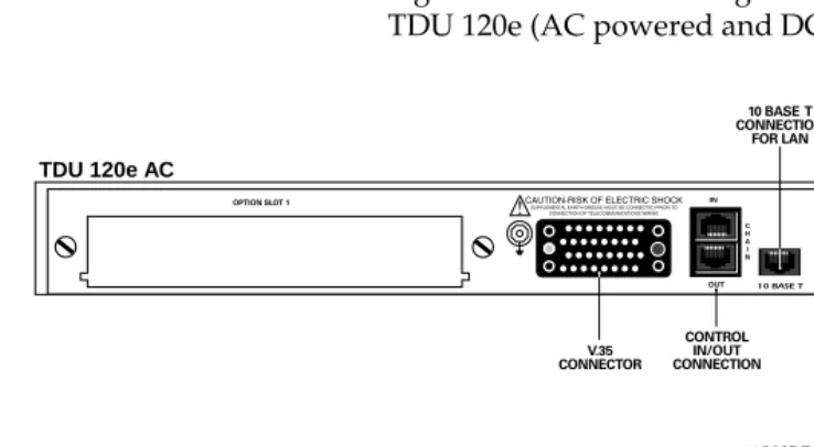
IDENTIFICATION OF REAR PANEL LAYOUT
Figure 2-1 shows the configuration of the rear panel of the TDU 120e (AC powered and DC powered units).
Figure 2-1. TDU 120e Rear Panels
TDU 120e AC
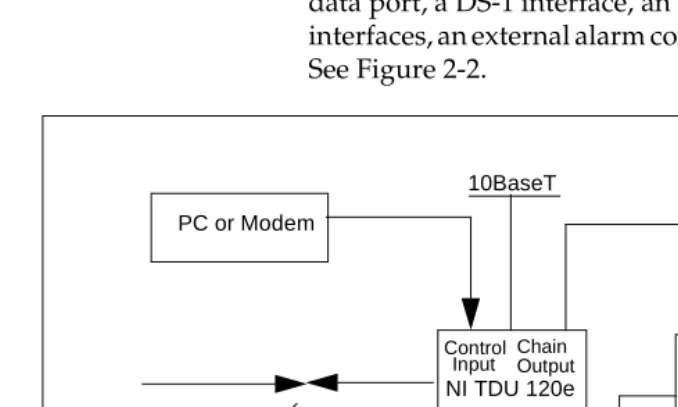
TDU 120e Interfaces
The TDU 120e rear panel is equipped with an Nx/DBU data port, a DS-1 interface, an option slot, management interfaces, an external alarm connector, and a T1 interface. See Figure 2-2.
Figure 2-2. TDU 120e Interfaces
Network Interface
The Network Interface (NI) port provides the connection to the T1. This port complies with the applicable ANSI and AT&T standards. For more information see Appendix B.
Nx56/64 Serial Interface
The Nx56/64 provides a serial V.35 port that operates from 56 kbps to 1.536 Mbps. This port provides 511 pat-tern generation and detection and remote loopback capa-bility.
10BaseT PC or Modem
NI TDU 120e NI TDU 120e
Chain Input OutputChain
Option Nx56/64 Chain
Output Control Input
DS-1 DS-1
Nx56/64 Option
PBX V.35 DS-1 V.35
DS-1 (PBX) Interface
The DS-1 interface provides a T1 for a PBX or other equip-ment. This port complies with ANSI T1.102. It can be soft-ware configured for either long-haul or short-haul.
Control In Port
The control port input provides an RJ-45 input from a PC or a modem for control of the TDU 120e. You can also use it as a chain input from another TDU 120e or TSU 100. For more information, see Appendix B.
Craft Port
The craft port provides the same functionality as the Con-trol Port Input. Both the craft port and the conCon-trol port in-put may be connected simultaneously, but only one port may be active at a time. For more information, see Appendix B.
Control Out Port
The chain port output provides an RJ-45 output to chain control to other TDUs or to TSUs. For more information see Appendix B.
10BaseT Interface
The 10BaseT interface provides the LAN interface for managing the TDU 120e with SNMP or T-Watch PRO. For more information, see Appendix B.
External Alarm Connector
POWER UP TESTING
When shipped from the factory, the TDU 120e is set to fac-tory default conditions. At the first application of power, the unit automatically executes a memory self-test. A full self-test can be run from the terminal. A passcode and unit ID may be set using the UTILITY menu. See page 6-3.
Self-Test
The full self-test procedure (invoked from the terminal or T-Watch PRO) consists of the following tests:
When... Then...
Initiating a self-test The terminal displays System Self-test Now Testing and Memory Test Now Testing. The test LEDs are illuminated.
The self-test is completed All LEDs go back to their normal state. The terminal momentarily displays System Self-test Tests passed.
A failure is detected A list of failures is displayed on the terminal.
Type of Test Explanation
Board level tests The TDU 120e contains an on-board processor which executes a series of tests checking the circuitry on the board.
RAM and EPROM tests
Verify on-board circuitry
Unit level tests Front panel LED verification
Board-to-board interface test
INITIALIZATION
Set User Passcode
The TDU 120e is designed to operate with or without the use of a passcode. The default condition is without a pass-code.
The passcode should be a number easily remembered. Once entered, the passcode is required to access any op-eration other than viewing. See Set Passcode on page 6-3 for details.
Set Unit Identification
The UNIT ID sets the unit to respond to remote control (controlled by a device other than the front panel or ter-minal). If no Unit ID is recorded it is not possible to oper-ate from any remote control device, including the local PC for T-Watch PRO or SNMP. See Unit ID on page 6-3 for details.
Set Control Port
The TDU 120e can be configured from the control port when T-Watch PRO, SNMP, or the terminal interface are being used. If the control port is to be used, the control port baud rate must also be selected.
Chain In (PC)
The unit can be controlled from an external PC connected directly or via modem to the Chain-In port. When using Chain-In, the selection of the Control Port baud rate from 9600 (factory default), 1200, 2400, or 4800, 19200, or 38400 must be made using the UNIT CONFIGURATION menu. See Unit Menu on page 5-14 for details.
Chain In/Chain Out
TDU 120e units and other TDUs and TSUs can be linked together to form a chain. Figure 2-3 provides an example of a chain-in arrangement with a PC or a modem. The first TDU 120ein the chain receives controlling input from the PC or modem.
Figure 2-3. Example of Chain-in
Subsequent TDU/TSUs in the chain are in a position to in-take information from another TDU or TSU. This in-tak-ing of information from another TDU in the chain is identified as Chain In. The baud rate for the chained units must match that of the first unit.
Unless locked out externally, the front panel can also con-trol the unit.
TDU 120e
PC or Modem
At this point, the unit initialization procedure is conclud-ed. If the unit is to be configured remotely, there are no additional items necessary to complete prior to executing remote configuration.
The Passcode, the Unit ID, and the Control Port settings are stored in a nonvolatile memory. This ensures they are operable for subsequent power-up sequences.
NORMAL POWER-UP PROCEDURE
After the unit has been put into operation with the initial power-up and initialization, subsequent power-up proce-dure includes only the Power-Up self-test followed by the request for a passcode (password) if this option was se-lected during initialization.
MENU OPERATION
The TDU 120e uses a VT-100 type terminal to display con-trol and monitor menus. Initiate this mode by keying in
<CTRL> PTT on the terminal once it is connected to the Control In or Craft port.
When you begin the Telnet session, you will be prompted for a password. The default password is ADTRAN. You can change this password using the MANAGEMENT sub-menu.
For detailed information on this method of control, see the Telnet/Terminal Main Menu onpage 3-5.
You can also connect to the TDU 120e via Telnet. Before attempting to connect via Telnet, first define the IP ad-dress, the default gateway, and the subnet mask.
See DEFAULT UNIT PASSCODE in the Unit Access Table on page 8-2 for details. The Telnet session will time-out after a predefined value that is also set in the MANAGEMENT menu.
Sample Terminal Screen with TDU 120e Menu
An example of a PC screen with a TDU 120e menu is shown in Figure 3-1.
Figure 3-1. Sample Terminal Screen with TDU 120e Menu
General Menu Traversal
The TDU 120e uses a multilevel menu structure contain-ing both menu items and data fields. All menu operations and data are displayed on the terminal.
Select and Activate a Menu Item
To choose a menu item, place the cursor on the desired menu item by:
• pressing the number corresponding to the menu item, or
• using the up and down arrows.
Main Menu
1) Status
2) Config
3) Util
4) Test
5) Remote Menu Access
6) Management Config
7) Flash Download
8) Quit Session
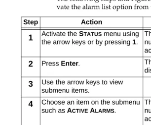
The following steps and Figure 3-2 describe how to acti-vate the alarm list option from the Status Menu.
.
Figure 3-2. Example of Basic Menu Travel
Step Action Result
1
Activate the STATUS menu using the arrow keys or by pressing 1.The cursor will flash on the number next to the
activated selection.
2
Press Enter. The STATUS submenus willdisplay.
3
Use the arrow keys to view submenu items.4
Choose an item on the submenu such as ACTIVE ALARMS.The cursor will flash on the number next to the
activated selection.
5
Press Enter. The ACTIVE ALARM LIST will display.6
View the ALARM LIST.1) NETWORK (NI) PERFORMANCE REPORTS
2) NETWORK (NI) ERRORS
3) ACTIVE ALARMS (ALARM LIST)
4) VIEW HISTORY END OF LIST
STATUS 5) PORT STATUS
6) REMOTE PORT
7) CLEAR PORT ALARM
Edit the Data Field
You can edit data fields preceded by a colon (:). To edit a data field perform the following steps:
Exit Any Menu Field Operation or Display
Press Escape as many times as required to return to the desired menu level.
Data Port Identification
When configuring the unit, menu selections will include options from data port submenus. Selecting data ports is necessary because the TDU 120e uses a Slot-Port method to identify the data port the menu item is referencing. If a module containing a PBX DSX-1 option card with an Nx56/64 plug-on interface is installed in the option slot, it would be designated as:
DSX-1 Passthru (1.1) Where slot=1 and port=1.
The DSX-1 is located in the option slot and is the first port in that slot.
Nx56/64 (1.2)
Step Action Result
1
Position the cursor on the submenu item number and press Enter.The cursor moves to the data field (to the right of the submenu item name).
2
Using the space bar, scroll to scan the available value settings.The value settings display one-at-a-time in the data field position.
3
When the desired value isdisplayed in the data field position, press Enter to set that value.
When the value is set, the cursor moves back to the submenu item position.
4
Select another submenu field or press Escape to return to the submenu.The Nx is located in the option slot and is the second port in that slot.
The ports that are built into the TDU 120e are referenced as Slot 0. The Nx/DBU is designated as 0.1 and the DS-1 is referenced as 0.2.
MENU STRUCTURE
Telnet/Terminal Main Menu
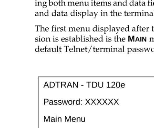
The TDU 120e uses a multilevel menu structure contain-ing both menu items and data fields. All menu operations and data display in the terminal window.
The first menu displayed after the Telnet/terminal ses-sion is established is the MAINmenu. See Figure 3-3. The default Telnet/terminal password is ADTRAN.
ADTRAN - TDU 120e
Password: XXXXXX
Main Menu
1) Status
2) Config
3) Util
4) Test
5) Remote Menu Access
6) Management Config
7) Flash Download
Menu Options
The opening menu is the access point to all other opera-tions. Each MAIN menu item has several functions and submenus to identify and access specific parameters.
Status
Displays all relevant information for the network and DTE interfaces. For detailed information on status options, see Chapter 4, Status Menu.
Config (Configuration)
Displays and sets the TDU 120e operational configura-tion, including all network interface parameters, the allo-cation of the DS0s, and the port parameters. For detailed information on configuration options, see Chapter 5, Con-figuration Menu.
Util (Utilities)
Displays and sets system parameters. For detailed infor-mation on utility options, see Chapter 6, Utility Menu.
Test
Initiates different types of unit tests and displays test results in the terminal window. For detailed information on test options, see Chapter 7, Test Menu.
Remote Access Menu
Management Configuration
Displays management information. For detailed infor-mation, see Chapter 8, Remote/Management Menus.
Flash Download
Allows you to manually perform a Flash download. For detailed information, see Chapter 8, Remote/Management Menus.
Quit Session
Terminates the Telnet/terminal session.
FRONT PANEL
The TDU 120e front panel monitors operation and con-trols the configuration of the unit. The TDU 120e front panel is shown in Figure 3-4.
Figure 3-4. TDU 120e Front Panel Layout
The following pages contain descriptions of each part of the front panel.
ACO REMOTE ACCESS CRAFT
TDU 120e AC NETWORK MON
IN OUT IN OUT IN OUT IN OUT PORT 0.2 MON
IN OUT IN OUT PORT 1.1 MON TEST OK YEL RED ALARM ERROR NETWORK STATUS TEST OK ALARM PORT STATUS 0.1 0.2 1.1 1.2 1.3 1.4
Alarm Cut Off Control Port
Active Unit Monitor JackNetwork Connection
For
Terminal Monitor JackDS-1 Status LED'sNetwork Port StatusLED's
ACO Switch
The Alarm Cut-Off (ACO) switch deactivates the alarm relay after an alarm condition has occurred. If the alarm that activated the alarm relay is cleared, then reoccurs, the alarm relay will re-energize.
Remote LED
The remote LED (yellow) indicates a management session (terminal mode or Telnet) is active. The LED does not ac-tivate (turn on) during SNMP sessions.
Craft Port
The Craft Port is used as an RJ-45 port to connect the unit to a computer, a modem, or to another TDU/TSU multiplexor or a TSU 100.
Network Monitor Jack
This jack connects the unit to the network.
DS1 Monitor Jack
LEDs
Network Status LEDs
The network status LEDs display the operational condi-tion of the network interface located on the controller board in the unit.
LED Display
Color Indicates that...
OK Green The operation is in the normal mode and no errors have been detected.
Test Yellow The network interface is operating in a test mode. This includes a self-test or a test loopback. When lighted, this LED also indicates that normal data flow is not occurring on the network interface.
Error Red An error has occurred, such as a BPV, OOF, or CRC.
Alarm Red An alarm condition has been detected. Any alarm condition will activate the alarm relay for the external alarm device. When the alarm condition is no longer valid, the OK LED activates (turns on). To view an alarm condition, select the active alarm menu item.
If the alarm conditions have been corrected, the alarm which caused the activation of the Alarm LED can be viewed under the UNIT HISTORY
Port Status LEDs
Port 1.1 Option Card Monitor Jacks
These are used to connect option cards to the computer.
LED Display
Color Indicates that...
OK Green The operation is in the normal mode and no errors have been detected.
Test Yellow One of the interfaces is operating in a test mode. This includes a self-test or a test loopback.
When lighted, also indicates that normal data flow is not occurring in at least one of the module ports.
Alarm Red An alarm condition has been detected. Any alarm condition will activate the alarm relay for the external alarm device. When the alarm condition is no longer valid, the OK LED activates (turns on).
To view an alarm condition, select the active alarm menu item.
If the alarm conditions have been corrected, the alarm which caused the activation of the Alarm LED can be viewed under the UNIT HISTORY
ALTERNATE METHODS OF CONTROL
T-Watch PRO (ADTRAN PC Program)
T-Watch PRO is the ADTRAN PC control program. It provides complete control over the configuration of the TDU 120e using a graphical interface. The T-Watch PRO program displays the same status and performance data as the terminal screen. This data is displayed in tables and graphs.
The T-Watch PRO program has the following capabilities:
• Interfaces with a modem which permits dialing into a remote TDU 120e location to configure the unit or read the status or performance of the unit.
• Receives traps from any TSU product.
• Records and creates display performance data over a 30-day period.
• Accesses units via the local area network (LAN).
Setting up the TDU 120e to Work over a LAN
To set up the TDU 120e to work with T-Watch PRO over the LAN, follow these steps:
Step Action
1
Set the Unit ID using the Front Panel. See Unit ID on page 6-3 for details.2
Set control port interface to Normal (10BaseT) or SLIP (chain-in port).3
Configure the IP address, default gateway, and subnet mask.Setting up the TDU 120e to Work over an EIA-232 Connection
To set up the TDU 120e to work with T-Watch PRO over a direct EIA-232 connection, follow these steps:
SNMP
The ADTRAN TDU 120e supports the Simple Network Management Protocol (SNMP) through the 10BaseT or chain in (SLIP) interface. See Appendix A, Understanding SNMP, for more information.
To use SNMP with the TDU 120e, follow these steps:
Step Action
1
Set the Unit ID and set a passcode. See page 6-3.2
Set the control port rate to the same setting as the PC Com port.3
Connect the PC Com port to the Chain-In port on the TDU 120e using the DB-25 adapter and modular cable provided.4
Follow the installation instructions for T-Watch PRO to start the program and connect to the unit.Step Action
1
Set the control port to either Normal (10BaseT) or SLIP (Chain-in port).2
Set the IP address, default gateway, and subnet mask through the front panel.3
Load the appropriate MIB browser into the Network Management Station. The MIB browser issues SNMP and sets the TDU 120e.STATUS
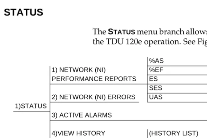
The STATUS menu branch allows you to view the status of the TDU 120e operation. See Figure 4-1.
Figure 4-1. Status Menu Tree
Menu flow is depicted from left to right. At every level of the menu, pressingESCAPEreturns the system to the
pre-%AS 1) NETWORK (NI) %EF PERFORMANCE REPORTS ES
SES
2) NETWORK (NI) ERRORS UAS NETWORK (NI)
1)STATUS RED ALARM
3) ACTIVE ALARMS LOSS OF SIGNAL END OF LIST 4)VIEW HISTORY (HISTORY LIST)
END OF HISTORY
1) DTE DATA CLOCK 5) PORT STATUS Nx/DBU (0.1) 2) DTE STATUS
3) DTE PORT RATE 6) REMOTE PORT 4) DBU DATA/CNTRL
5) DBU CONTROL 6) DBU STATUS DS-1 (0.2) DS-1 ERRORS 7) CLEAR PORT ALARM (OPTION LIST)
Network (NI) Performance Reports
The NETWORK INTERFACE PERFORMANCE REPORTS (see Figure 4-2) display the performance data. The TDU 120e maintains this performance data on the network in com-pliance with ANSI T1.403 and AT&T document TR54016. The data displayed is data accumulated over the last 15 minutes and over the last 24 hours.
Figure 4-2. Network Interface Performance Report
Where Means
%AS Percentage of available seconds
%EF Percentage of error free seconds
ES Number of errored seconds (1 or more errors/second)
SES Number of severely errored seconds (more than 320 errors/second)
UAS Number of unavailable seconds (10 or more consecutive seconds)
Network Interface (NI) Errors
The NI Errors submenu displays the types of errors the Network Interface (NI) detects. A blinking CSU error LED indicates that network errors are detected.
The asterisk (*) above an item indicates the type of errors detected. The error types are listed below:
CRC
CRC-6 bit errors based on the FDL. This is valid only in ESF mode.
BPV
Bipolar violations
XSO
Excess zeros
FER
Framing errors
Active Alarms
This menu item displays a list of current alarms reported by either the base controller or any of the ports. If no alarms are current, using this menu item displays ENDOF
LIST.
This display (see Table 4-1 on page 4-4) includes two text fields. The left field is the alarm source. The right field is the alarm message. A list of alarm messages is found in Appendix C, System Messages.
Table 4-1. Alarm Message Display
View History
This menu item both displays and clears the accumulated status changes of the unit.
VIEW HISTORY displays a history of the last 20 status changes in the unit, including the date, time, and type of change. The unit also records for viewing the date and time an alarm became active and inactive, as well as the date and time of test activation and deactivation.
To clear the VIEW HISTORYdisplay, press C.
Port Status
PORT STATUSdisplays the signals monitored on the data ports. For example, the Nx/DBU interface monitors the RTS, CTS, RD, and RD, along with other signal lines. When a port is selected, the terminal indicates if the signal is present.
The base Nx interface shows the status screen listed in this section. When using other option cards, refer to the ap-propriate separate manual for a definition of any status screens offered.
The PORT STATUS of Nx/DBU shows how to use this item.
Active Alarms
Network (Ni)
Red Alarm
Loss Of Signal
Nx/DBU (0.1) Menu Items
DTE Data/Clock
An asterisk (*) indicates an active status of the following lines:
TXD
Transmit data from the DTE
RXD
Receive data toward the DTE
XSO
Excess zeros from the DTE
LCK
Lock status of the phase locked loop
DTE Status
An asterisk (*) indicates an active status of the following lines:
RTS
Request to send from DTE
CTS
Clear to send to DTE
DCD
Data carrier detect to DTE
DSR
Data set ready to DTE
DTE Port Rate
DBU Data/CNTRL
An asterisk (*) indicates an active status on the following lines:
TXD
Transmit data to the DCE
RXD
Receive data from the DCE
DCD
Data carrier detect from the DCE
RI
Ring indicate from the DCE
DBU Control
An asterisk (*) indicates an active status on the following lines:
RTS
Request to send the DCE
CTS
Clear to send from the DCE
DTR
Data terminal ready to the DCE
DSR
Data set ready from the DCE
DBU Status
DBU SECS
Total seconds in current DBU session
IN DBU
DS-1 (0.2) Menu Items (DS-1 Errors)
CRC
An asterisk displays under the CRC if there are CRC errors in extended superframe format (ESF) mode. If the DS-1 is configured for D4 Frame format, the terminal dis-plays N/A.
BPV
An asterisk displays under the BPV if the DS-1 detects bipolar violations.
SLIP
An asterisk displays under the SLIP if the DS-1 detects frame slips. This is caused by multiple clock sources in the application.
FER
An asterisk displays under the FER if the DS-1 detects frame bit synchronization errors.
Remote Port
REMOTE PORT displays the status of activity on the Con-trol In remote port. This is useful for troubleshooting communication sessions, and for verifying cabling.
RX
Characters received at remote port
ID
Unit ID received at remote port
CRC
Correct CRC received
PC
Clear Port Alarm
Clears the LINK FAILEDalarms on option modules that have been removed from the TDU 120e chassis.
Ethernet Status
TX
Indicates that data is being transmitted from the 10BaseT port.
RX
Indicates that data is being received by the 10BaseT port.
LNK
Indicates the current status of the 10BaseT link integrity test (this should always be on when the unit is connected to a functional 10BaseT hub).
CPU
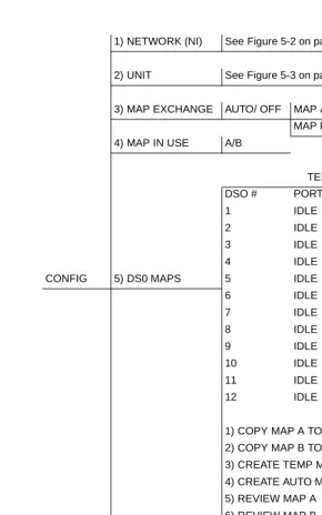
CONFIG
The CONFIGURATIONmenu sets the TDU 120e operational configuration, including all network interface parame-ters, the allocation of the DS0s, and the port parameters. See the TDU 120e Config Menu Tree on page 5-2.
1) NETWORK (NI) See Figure 5-2 on page 5-3.
2) UNIT See Figure 5-3 on page 5-4.
3) MAP EXCHANGE AUTO/ OFF MAP A@00:00* MAP B@00:00* 4) MAP IN USE A/B
TEMP MAP
DSO # PORT DSO# PORT
1 IDLE 13 IDLE
2 IDLE 14 IDLE
3 IDLE 15 IDLE
4 IDLE 16 IDLE
CONFIG 5) DS0 MAPS 5 IDLE 17 IDLE
6 IDLE 18 IDLE
7 IDLE 19 IDLE
8 IDLE 20 IDLE
9 IDLE 21 IDLE
10 IDLE 22 IDLE
11 IDLE 23 IDLE
12 IDLE 24 IDLE
1) COPY MAP A TO TEMP MAP 2) COPY MAP B TO TEMP MAP
3) CREATE TEMP MAP
4) CREATE AUTO MAP 5) REVIEW MAP A
6) REVIEW MAP B 7) REVIEW TEMP MAP 8) EDIT TEMP MAP
9) APPLY TEMP MAP TO MAP A
10) APPLY TEMP MAP TO MAP B
CONFIG -- Select Port 1) PORT 1
6) PORT CONFIG 2) PORT 2
3) PORT 3
N) EXIT COMMAND:
7) EXIT
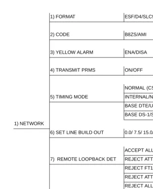
Figure 5-2. Network (NI) Menu Tree
1) FORMAT ESF/D4/SLC96
2) CODE B8ZS/AMI
3) YELLOW ALARM ENA/DISA
4) TRANSMIT PRMS ON/OFF
NORMAL (CSU)
5) TIMING MODE INTERNAL/NETWORK (NI)
BASE DTE/U-BR1TE (SLOT 1)
BASE DS-1/SECONDARY (SI)
1) NETWORK
6) SET LINE BUILD OUT 0.0/ 7.5/ 15.0/ 22.5/ AUTO
ACCEPT ALL
7) REMOTE LOOPBACK DET REJECT ATT
REJECT FT1
REJECT ATT & FT1
REJECT ALL
8) BIT STUFFING ENABLE/ DISABLE
9) TR-08 OPTIONS 1) ALARM REPORT [SEND ALARMS/DISABLE ALARM
2) ALARM FORMAT [ORB-13/ORB-16
3) BPV THRESHOLD [10-4/10-6/10-5]
4) EXIT
Figure 5-3. Unit Menu Tree 1) CONTROL PORT RATE 38400 / 19200 / 9600 / 2400 / 1200
2) TRAPS ENABLE/DISABLE
3) ACCESS DIRECT/DIAL
NONE
4) INIT. MODEM CUSTOM
HAYES
MOTOROLA
USR COURIER
2) UNIT 5) CONTROL PORT: NORMAL
6) IP ADDRESS 000.000.000.000
7) SUBNET ADDRESS: 000.000.000.000
8) DEFAULT ROUTER: 000.000.000.000
9) SLIP RATE: 38400 / 19200 / 9600 / 2400 / 1200
10)SLIP FLOW CONTROL NONE/HARDWARE
11) PROXY TRAPS ENABLE/DISABLE
12) EXTERNAL ALARMS ENA/DISA
NETWORK (NI)
This menu item accesses the configuration of parameters associated with the network interface in the base unit. There are nine submenu items that include setting the for-mat, the line build out (LBO), and the timing mode. Sub-menu items do not include setting the parameters which may be necessary for a secondary interface
(DS-1 Passthru, etc.).
Network (NI) Menu Items
FORMAT
Sets the frame format for the NI. Choices: D4, ESF, SLC96.
CODE
Sets the line code for the NI. Choices: AMI and B8ZS.
YELLOW ALARM
Enables and disables the transmitting of yellow alarms. Choices: ENABLED and DISABLED.
TRANSMIT PRMS
Enables and disables the sending of PRM data on the facility data link (FDL). The PRM data continues to be collected even if Transmit PRMS are disabled (possible only with ESF Format).
TIMING MODE
Selects the clock source for transmission toward the net-work from the NI.
Choices: NETWORK, BASE DTE, BASE DS-1, NORMAL
(CSU) (only with DSX-1 option card), U-BR1TE (only with U-BR1TE option card), INTERNAL, and SECONDARY
(SI) (only with secondary port option card).
The selected clock option always designates the clock source for
Network Timed
The network is the source of timing. The received data clocking is looped back to the network, where it is used to determine the transmission timing. This option is also referred to as loop timed as the trans-mission clock is derived from the received clock. See Figure 5-4.
Figure 5-4. Network Timed Clock Source
INTERNAL OSCILLATOR
SECONDARY INTERFACE OPTION CARD NETWORK
INTERFACE
BASE Nx56/64 BASE DS-1
PBX DTE CLOCK
T1 Transmit
Base DS-1
The PBX is the source of timing. The TDU 120e uses the clock derived by the Base DS-1 interface for transmission timing. See Figure 5-5.
Figure 5-5. Base DS-1 Timed Clock Source
INTERNAL OSCILLATOR
SECONDARY INTERFACE OPTION CARD NETWORK
INTERFACE
BASE Nx56/64 BASE DS-1
PBX DTE CLOCK
T1 Transmit
Base DTE Timing
The Base DTE is the source of timing. The TDU 120e uses the incoming DTE clock to determine the trans-mission timing. This is typically used in applications where it is necessary to have the DTE as the primary clock source (such as limited distance line drivers). See Figure 5-6.
INTERNAL OSCILLATOR
SECONDARY INTERFACE OPTION CARD NETWORK
INTERFACE
BASE Nx56/64 BASE DS-1
PBX DTE CLOCK
T1 Transmit
Internal Timing
The TDU 120e is the source of timing. The TDU 120e is configured to use its own internal oscillator as the source of timing. Applications include private line driver circuits where one end is set to network and the other to internal. See Figure 5-7.
Figure 5-7. Internal Clock Source
INTERNAL OSCILLATOR
SECONDARY INTERFACE OPTION CARD NETWORK
INTERFACE
BASE Nx56/64 BASE DS-1
PBX DTE CLOCK
T1 Transmit
Secondary Timing
The secondary interface is the source of timing. The TDU 120e uses the clock derived by the secondary interface for transmission timing. See Figure 5-8.
Figure 5-8. Secondary Clock Source
INTERNAL OSCILLATOR
SECONDARY INTERFACE OPTION CARD NETWORK
INTERFACE
BASE Nx56/64 BASE DS-1
PBX DTE CLOCK
T1 Transmit
Normal (CSU) Timing
The typical timing option arrangement is shown in Figure 5-9. The PBX is looped timed sending data to the TDU 120e which is actually synchronous to the received data. The Network Interface (NI) is the actual source of all timings. This timing option is the same as that typically used for CSUs. It works equally well when the PBX is the source of timing. In that configuration the network would not be provid-ing timprovid-ing.
Figure 5-9. Normal (CSU)
INTERNAL OSCILLATOR
SECONDARY INTERFACE
OPTION CARD NETWORK
INTERFACE
BASE Nx56/64 BASE DS-1
PBX 2
DTE CLOCK T1 Transmit
T1 Receive
PB
X 1
U-BR1TE
The timing selection U-BR1TE works like NORMAL (CSU) except that timing is derived from the U inter-face on port 1.1.
Set Line Buildout
Selects the line buildout for the network interface. In AUTO mode, the TDU 120e sets the LBO based on the strength of the receive signal and displays the selected value.
Choices: 0.0 dB, 7.5 dB, 15 dB, 22 dB, and Auto.
Remote Loopback Det
Sets unit to accept or reject the network interface loop-up and loop-down codes as defined in ANSI T1.403.
Choices: ACCEPT ALL, REJECT ATT, REJECT FT1, REJECT
ATT & FT1, REJECT ALL.
Bit Stuffing
When enabled, bit stuffing causes the TDU 120e to moni-tor for ones (1s) density violations and insert a one (1) when needed to maintain 1s at 12.5%.
Choices: ENABLE or DISABLE.
TR-08 Options
The TR-08 submenu configures the unit for TR-08 appli-cations. The submenu items and their descriptions fol-low:
Alarm Report
Enables and disables the transmission of alarm reports. Choices: SEND ALARMS, DISABLE ALARMS
Alarm Format
Sets the alarm format to 13 frames or 16 frames. Choices: ORB-13, ORB-16
BPV Threshold
Sets the threshold for BPVs to trigger an alarm. Choices: 10-4, 10-5, 10-6
Exit
This selection will exit to the main configuration menu.
Unit Menu
The Unit menu changes the baud rate of the Control In port and the setup of the Dial Out port. The menu items are:
Control Port Rate
Sets the baud rate for communication with the PC or modem.
Choices: 1200, 2400, 9600, 19200,and 38400 KBPS
Traps
Enables or disables the transmission of trap messages. Choices: ENABLE and DISABLE
Access
Sets the method of connection from the TDU 120e to T-Watch PRO or SNMP.
Choices:
Direct: Used if connected directly to the PC.
Dial: Used when connection is through a modem. The dial string is entered from T-Watch PRO or SNMP.
Init Modem
Allows you to choose an industry standard or a custom initialization string for a modem connected to the control port.
Choices: NONE, CUSTOM, HAYES, MOTOROLA, and USR
Control Port
Selects the TCP/IP physical interface: Normal (10BaseT Ethernet) or SLIP using the RS-232 serial port.
Choices: NORMALor SLIP
IP Address
This is the IP address that uniquely identifies the TDU 120e on a TCP/IP network. This address is composed of four decimal numbers, each in the range of 0 to 255, sepa-rated by periods. This value is used for either the 10BaseT Ethernet or SLIP interface, depending on the control port setting.
Subnet Address
This defines which part of a destination IP address is the Network number. It is used along with the TDU 120e IP address to determine which nodes must be reached through the default IP Gateway. This value is set to 0.0.0.0 when the control port option is set to SLIP.
Default Router
All IP Packets destined for nodes not on the TDU 120e unit’s local network are not forwarded through this IP address. Normally, this address defines a router con-nected to the TDU 120e unit’s local network. This value is ignored when the control port option is set to SLIP.
SLIP Rate
This sets the baud rate for the Chain-In port when used as the SLIP connection for SNMP management.
Choices: 1200, 2400, 9600, 19200, 38400
SLIP Flow Control
This is used to activate flow control on the Chain-In port when used as the SLIP interface. Hardware mode uses RTS and CTS.
Choices: NONE, HARDWARE
Proxy Traps
This determines whether or not traps are forwarded to the IP Interface from units being “proxied” for.
Choices: ENABLE, DISABLE
External Alarm
Sets unit to accept or reject external alarms attached to Pin 6 or Pin 7 of the Chain-In Port. A connection to ground indicates an alarm condition.
Choices: ENABLE, DISABLE Exit
This selection will exit to the main configuration menu.
Map Exchange
The MAP EXCHANGE menu enables and sets the automatic time of day map switch. The unit provides selection of the hour, minute, and seconds for the map switching to take place. The menu items are:
OFF
Indicates the map in use does not change. The automatic map change feature is disabled.
AUTO
Indicates that the map in use will change at a user-selected time of day. The automatic map change feature is enabled.
After editing Map A, press Enter to record the Map A set-tings and activate the selection fields for Map B. Use the same operation to edit switching time for Map B.
When ESF is used with an FDL channel between units, the units automatically coordinate the automatic map switch by sending a map switch command from end-to-end over the FDL. Only one end-to-end needs to be set to AUTO for this to work.
Map In Use
This menu item controls the DS0 map the TDU 120e uses and displays the map in current use.
DS0 Map A and DS0 Map B
The DS0 maps designate which DS0s are assigned to which port. The three maps are:
DS0 Map A
Default map.
DS0 Map B
Alternate map.
Temp
DS0 Maps Configuration Menu
The DS0 maps configuration menu takes advantage of the 24-line VT-100 display. Upon entering this menu, the current Temp (temporary) map displays and is followed by nine selections that you can use for configuring and reviewing map information. See Figure 5-10.
Figure 5-10. DS0 Temp Map
You can use theup and down arrows or number keysto move the cursor from one selection to another. Press
Enter to perform the action displayed to the right of the
cursor. TEMP MAP DS0# 1 2 3 4 5 6 7 8 9 10 11 12 PORT IDLE IDLE IDLE IDLE IDLE IDLE IDLE IDLE IDLE IDLE IDLE IDLE DS0# 13 14 15 16 17 18 19 20 21 22 23 24 PORT IDLE IDLE IDLE IDLE IDLE IDLE IDLE IDLE IDLE IDLE IDLE IDLE 1) COPY MAP A TO TEMP MAP
2) COPY MAP B TO TEMP MAP 3) CREATE TEMP MAP 4) REVIEW MAP A 5) REVIEW MAP B 6) REVIEW TEMP MAP 7) EDIT TEMP MAP
Creating a DSO Map
To configure a DS0 Map, perform the following steps:
Initializing the Temp Map
Upon entering the DS0 maps CONFIGURATION menu, the Temp map reflects its last configured state.
Step Explanation
1
Initialize the TEMP Map to one of three configurations (current Map A, current Map B, or all IDLE). This step is optional.2
Edit the Temp Map so that it reflects the desired map configuration.3
Replace the current DS0 Map A or B configuration with the Temp map configuration.If you want to... Enter selections...
Initialize the Temp map from its current configuration to one which reflects the currently stored Map A or B configurations, respectively.
1 - 2
Initialize the Temp map to an all IDLE state.
Editing the Temp Map
If further changes to the TEMPmap are needed, do the following:
Applying the Temp Map
Once the Temp map reflects the desired configuration, use selections 8 or 9 to apply this configuration to Map A or B, respectively.
Copying Map
To copy Map A to Map B, copy Map A to the Temp map and then apply the Temp map to Map B. See Figure 5-11.
Step Action Explanation
1
Use selection 7 to enter theTemp map edit mode.
Upon entering this mode, the cursor location moves to DS0 number one in the DS0 field of the Temp map.
2
Move the cursor from oneDS0 to another by using the up and down arrows
Locate the DS0 number whose assigned port needs to be changed.
3
Press Enter. The cursor will move into the PORTfield.
4
Use the up and downarrows to scroll through the
possible port selections.
To restore the previous port
assignment and return to the DS0 field, press ESC.
5
To save the current selectedport and return to the DS0 field, press Enter.
6
When the cursor is againlocated in the Temp map DS0 field, press Esc.
Figure 5-11. DS0 Map Designations
Reviewing Maps
Selections 4 through 6 give a summary of the number of ports assigned to Map A, Map B, and the Temp map, respectively. The menu items and their descriptions fol-low:
Copy Map A (B) to Temp Map
Copies the current map A (B) into a TEMP map area.
This permits modification without disturbing the existing map. When the modifications are com-pleted, the TEMP map is written to current MAP A (B) by selecting APPLY TEMP MAPTO MAP A (B). Create Temp Map
Creates a map by defining a port or Idle for all DS0s. When CREATE TEMP MAPis first selected, all DS0s are set to Idle.
Possible port selections include IDLE, TST, + option module ports.
TST designates which DS0s are used for QRSS test-ing when activated under the TEST menu.
When not used for testing, the TST designation is identical to IDLE.
T E M P
Review Map A (B)
Permits a quick review of the number of DS0s assigned to each port and the number of unassigned DS0s (IDLE
or TST) as defined in the currently applied Map A (B).
Review Temp Map
This menu item is operated the same as REVIEW MAP A
(B).
Edit Temp Map
The map in the TEMP file can be edited to whatever con-figuration is desired. If Map A had been copied into the TEMP file, then after editing, the TEMP file could be applied to MAP A or MAP B.
Apply Temp to Map A (B)
Writes the TEMP map into Map A (B). Apply is usually the last step in updating a map.
Port Configuration (Port Config)
PORT CONFIGURATIONselects and configures the parame-ters associated with any data port in the unit. For exam-ple, parameters for the DS-1 (PBX) interface are set through this menu. The items that can be set depend on which option module is installed. The list of option ports will vary with the configuration.
The CONFIGmenus for options ports are described in sep-arate sections of the manual supplied with the option card.
Nx/DBU (0.1) Menu Items
The Nx/DBU port has two main menus:
NX56/64 CONFIG -- Nx operation and DBU CONFIG-- DBU operation.
Nx56/64 Config
Under NX56/64 CONFIG, the menu items are: DS0 RATE
This sets the base DS0 rate of the interface. The actual data rate depends on the number of DS0s assigned to the Nx port.
Choices: 56K OR 64K TX CLK CNTRL
Controls the clock used by the TDU 120e to accept transmit (TX) data from the DTE. The default is
NORMAL. If the interface cable is long, causing a phase shift in the data, the clock can be selected as
INVERT. This switches the phase of the clock which should compensate for a long cable.
Choices: NORMAL, INVERT DATA
Used to control the inverting of the DTE data. This inversion can be useful when operating with an HDLC protocol. Often used as a means to ensure 1s density.
Choices: NORMALor INVERT