Electronic Thesis and Dissertation Repository
1-8-2013 12:00 AM
Development of Novel Nano-structured Materials with Low-Cost
Development of Novel Nano-structured Materials with Low-Cost
and High Stability for PEM Fuel Cell
and High Stability for PEM Fuel Cell
Dongsheng Geng
The University of Western Ontario
Supervisor
Dr. Andy (Xueliang) Sun
The University of Western Ontario
Graduate Program in Mechanical and Materials Engineering
A thesis submitted in partial fulfillment of the requirements for the degree in Doctor of Philosophy
© Dongsheng Geng 2013
Follow this and additional works at: https://ir.lib.uwo.ca/etd
Part of the Nanoscience and Nanotechnology Commons
Recommended Citation Recommended Citation
Geng, Dongsheng, "Development of Novel Nano-structured Materials with Low-Cost and High Stability for PEM Fuel Cell" (2013). Electronic Thesis and Dissertation Repository. 1071.
https://ir.lib.uwo.ca/etd/1071
This Dissertation/Thesis is brought to you for free and open access by Scholarship@Western. It has been accepted for inclusion in Electronic Thesis and Dissertation Repository by an authorized administrator of
(Spine title: Nano-structured cathode Materials for fuel cell)
(Thesis format: Integrated Article)
by
Dongsheng Geng
Graduate Program in Mechanical and Materials Engineering
A thesis submitted in partial fulfillment of the requirements for the degree of
Doctor of Philosophy
The School of Graduate and Postdoctoral Studies The University of Western Ontario
London, Ontario, Canada
ii
School of Graduate and Postdoctoral Studies
CERTIFICATE OF EXAMINATION
Supervisor
______________________________ Dr. Xueliang (Andy) Sun
Supervisory Committee
______________________________ Dr. Liying Jiang
______________________________ Dr. Jun Yang
Examiners
______________________________ Dr. Robert J. Klassen
______________________________ Dr. Liying Jiang
______________________________ Dr. Paul A. Charpentier
______________________________ Dr. Aiping Yu
The thesis by
Dongsheng Geng
entitled:
Development of Nano-structured Materials with Low-cost and High
Stability for PEM Fuel Cell
is accepted in partial fulfillment of the requirements for the degree of
Doctor of Philosophy
______________________ _______________________________
iii
Abstract
Polymer electrolyte membrane fuel cells (PEMFCs) are non-polluting and efficient energy conversion devices that are expected to play a dominant role in energy solutions of the future. However, due to high cost and known degradation issue of Pt electrocatalyst, more durable, efficient, and inexpensive electrocatalysts are required before fuel cells can become commercially viable. This research is revolving around the development of electrocatalysts such as non-noble metal oxygen reduction reaction (ORR) catalyst, new alternative supports, and novel Pt nanostructures to address the above-mentioned challenges in PEMFCs.
Firstly, we report the synthesis of nitrogen doped carbon nanotubes (CNx) and nitrogen doped
graphene (N-graphene) with the various nitrogen contents. The relationship between structures and ORR activity is investigated in detail. We identified the real active site by the study. Most importantly, CNx and N-graphene have the comparable ORR activity even the
improved durability compared with a platinum-based catalyst, showing the potential to replace costly Pt/C catalyst in alkaline fuel cells.
Secondly, due to the advantages of N-graphene as not only a support of Pt but the non-noble metal ORR catalyst, we developed three different methods to prepare it: (i) post-treatment of graphene with ammonia (ii) from CNx to N-graphene directly (iii) one-step solvothermal
process. Especially, by the solvothermal method, for the first time, nanoflower-like N-graphene was obtained with pure sp2 hybridized carbon and the controllable nitrogen types. Importantly, the synthesized materials exhibit much higher durability as Pt support for fuel cells than commercial carbon powder.
Thirdly, previous results have shown that star-like Pt nanowires have both good catalytic activity and durability for ORR. However, there is a limitation in scale up and controlling length and shape of Pt nanowire for previous method. Here we report a universal method to address the challenge. It is a very simple, green and efficient wet chemical route without any surfactant and template to produce urchin-shaped Pt nanostructures in high yield.
iv
v
Co-Authorship Statement
1.
Title: Non-Noble Metal Oxygen Reduction Electrocatalysts Based on Carbon Nanotubes with Controlled Nitrogen Contents
Authors: Dongsheng Geng, Hao Liu, Yougui Chen, Ruying Li, Xueliang Sun, Siyu Ye, and Shanna Knights
All the experimental and theoretical work was carried out by Dongsheng Geng under the guidance of Dr. Xueliang Sun. Hao Liu did previous research work on the synthesis of nitrogen doped carbon nanotubes. Siyu Ye revised the manuscript. The other coauthors contributed to the formation of the final version with discussion and related characterization. The final version of this manuscript has been published in Journal of Power sources, 2011,
196, 1795-1801.
2.
Title: Nitrogen Doping Effects on the Structure of Graphene
Authors: Dongsheng Geng, Songlan Yang, Yong Zhang, Jinli Yang, Jian Liu, Ruying Li, Tsun-Kong Sham, Xueliang Sun, Siyu Ye, and Shanna Knights
Dongsheng Geng designed and conducted experiments, collected data, and wrote the manuscript. The initial draft and the followed modifications of this manuscript were conducted by Dongsheng Geng under the supervision of Dr. Xueliang Sun. Songlan Yang did the experiment of near-edge X-ray absorption fine structure (NEXAFS). Tsun-Kong Sham revised the data analysis of NEXAFS and the manuscript. The other coauthors contributed to the formation of the final version with discussion and related characterization. The final version of this manuscript has been published in Applied Surface Science, 2011,
257, 9193-9198.
vi
Authors: Dongsheng Geng, Ying Chen, Yougui Chen, Yongliang Li, Ruying Li, Xueliang Sun, Siyu Ye, and Shanna Knights
Dongsheng Geng designed and conducted experiments, collected data, and wrote the manuscript. The initial draft and the followed modifications of this manuscript were conducted by Dongsheng Geng under the supervision of Dr. Xueliang Sun. Siyu Ye revised the manuscript. The other coauthors contributed to the formation of the final version with discussion and related characterization. The final version of this manuscript has been published in Energy & Environmental Sciences, 2011, 4, 760-764.
4.
Title: Nitrogen doped graphene oxide nanoribbons from Nitrogen doped carbon nanotubes
Authors: Dongsheng Geng, Yuhai Hu, Jian Liu, Ruying Li, Xueliang Sun, Siyu Ye, and Shanna Knights
Dongsheng Geng designed and conducted experiments, collected data, and wrote the manuscript. Jian Liu did previous research work on the synthesis of nitrogen doped carbon nanotubes. The other coauthors contributed to the formation of the final version with discussion and related characterization. The final version of this manuscript is to be submitted for publishing.
5.
Title: One-pot Solvothermal Synthesis of Doped Graphene with the Designed Nitrogen Type Used as a Pt Support for Fuel Cells
Authors:Dongsheng Geng, Yuhai Hu, Yongliang Li, Ruying Li, and Xueliang Sun
vii Communications, 2012, 22, 65-68.
6.
Title: A universal method to synthesize urchin-shaped Pt nanostructures
Authors: Dongsheng Geng, Shuhui Sun, Jinli Yang, Ruying Li, and Xueliang Sun
viii
Acknowledgments
This PhD work was carried out in Dr. Sun’s group at the University of Western Ontario. It is my pleasure to convey my sincere acknowledgements to every individual who contributed to my research and made this thesis possible.
At this moment, I would like to express my deep gratitude first to my supervisor, Dr. Xueliang Sun, the Canada Research Chair in Nanomaterials for Clean Energy, a professor in the Department of Mechanical & Materials Engineering at UWO, for providing me the opportunity to come to Canada and work under his guidance. His profound knowledge, rigorous attitude and enthusiasm in research benefit me for life long.
I am very grateful to Ms. Ruying (Kathy) Li, Dr. Sun’s wife and a research engineer in the group. She arranges everything perfect in our lab and enables us to do research smoothly. I would like to express my acknowledgements to Dr. Siyu Ye at Ballard and Prof. Tsun-Kong Sham at Department of chemistry, the University of Western Ontario, for their kind guidance and fruitful discussion on my work.
I also would like to thank Dr. Paul Charpentier, a professor in the Department of Biochemical and Chemical Engineering at UWO, Dr. Robert Klassen, Dr. Liying Jiang, the professors in MME at UWO, and Dr. Aiping Yu, a professor in chemical engineering at the University of Waterloo. As examiners of my defense, they all provided many helpful suggestions to improve my thesis.
Many thanks to all my group members in Dr. Xueliang (Andy) Sun’s group, Dr. Yong Zhang, Dr. Xiangbo (Henry) Meng, Dr. Shuhui Sun, Dr. Gaixia Zhang, Dr. Jiajun Wang, Dr. Mohhammad Norouzi Banis, Dr. Yougui Chen, Dr. Hao Liu, Dr. Yu Zhong, Dr. Yuhai Hu, Dr. Xifei Li, Dr. Liang Li, Harmid Norouzi Banis, Yongliang Li, Dongniu Wang, Jinli Yang, Jian Liu, Dr. Mihnea Ioan Ionescu, Dr. Niancai Cheng, Dr. Dawei Wang, Dr. Kun Chang, and Dr. Ying Chen. It was a so much pleasure to work with so many nice people. Without their collaboration, generous help, my project could not have been done so smoothly.
plasma-ix
University, who assisted me with HRTEM observation. My thanks also go to Mark C. Biesinger, a senior research scientist in surface science western, who helped me finish x-ray photoelectron spectroscopy (XPS) test and analysis.
Specially, I would like to express my sincere gratitude towards my parents and parents-in-law, for their understanding, support and encouragement, especially my heartiest thanks to my wife (Xiaohui Liu) for her love and dedication. I would also like to say “thanks” to my lovely daughter, Zichun for her contributions to our family with so much happiness.
Dongsheng Geng 1796 Devos Dr.
x
Table of Contents
CERTIFICATE OF EXAMINATION ... ii
Abstract ... iii
Keywords ... iv
Co-Authorship Statement... v
Acknowledgments... viii
Table of Contents ... x
List of Tables ... xv
List of Figures ... xvi
List of Abbreviations ... xxi
Chapter 1 ... 1
1 Introduction ... 1
1.1 Fundamentals of PEM fuel cells ... 1
1.2 Challenges of PEM fuel cells ... 3
1.3 Solutions for catalyst development ... 5
1.3.1 Modifying Pt main catalyst ... 6
1.3.2 Looking for the novel supports ... 7
1.3.3 Developing non-precious metal ORR catalyst ... 8
1.4 Objectives of thesis ... 10
1.5 Thesis structure ... 11
References ... 14
Chapter 2 ... 21
2 Experimental and characterization techniques ... 21
xi
floating catalyst chemical vapour deposition method ... 21
2.1.2 Synthesis of graphene by modified Hummers’ method ... 22
2.1.3 Synthesis of nitrogen doped graphene ... 22
2.1.4 Synthesis of S, P doped graphene ... 24
2.1.5 Synthesis of dendritic Pt nanostructures via a universal chemical method ... 24
2.2 Characterization techniques ... 25
2.2.1 Physical characterization (SEM, TEM, XPS, XRD, BET, and Raman spectra) ... 25
2.2.2 Electrochemical characterization ... 27
References ... 31
Chapter 3 ... 34
3 Non-Noble Metal Oxygen Reduction Electrocatalysts Based on Carbon Nanotubes with Controlled Nitrogen Contents ... 34
3.1 Introduction ... 36
3.2 Experimental ... 37
3.2.1 Preparation of CNx ... 37
3.2.2 Physical characterizations ... 37
3.2.3 Electrochemical characterization ... 37
3.3 Results and discussion ... 38
3.3.1 SEM, TEM and XPS analysis ... 38
3.3.2 ORR activities of CNx in acid solution ... 40
3.3.3 ORR activities of CNx in alkaline solution ... 44
3.4 Conclusions ... 49
Acknowledgments ... 49
References ... 50
xii
4.1 Introduction ... 56
4.2 Experimental ... 57
4.2.1 Preparation of graphene and N-graphene ... 57
4.2.2 Physical characterizations ... 58
4.3 Results and discussion ... 58
4.4 Conclusions ... 67
Acknowledgments ... 68
References ... 68
Supporting information ... 73
Chapter 5 ... 74
5 High Oxygen-Reduction Activity and Durability of Nitrogen-doped Graphene ... 74
5.1 Introduction ... 76
5.2 Experimental ... 77
5.3 Results and discussion ... 77
5.4 Conclusions ... 84
Acknowledgments ... 84
References ... 84
Chapter 6 ... 88
6 Nitrogen doped graphene oxide nanoribbons from Nitrogen doped carbon nanotubes88 6.1 Introduction ... 89
6.2 Experimental ... 90
6.3 Results and discussion ... 90
6.4 Conclusions ... 95
Acknowledgments ... 95
xiii
7 One-Pot Solvothermal synthesis of doped graphene with the designed nitrogen type
used as a Pt support for fuel cells ... 99
7.1 Introduction ... 101
7.2 Experimental ... 102
7.2.1 Sample preparation and characterization ... 102
7.2.2 Electrochemical test ... 103
7.3 Results and discussion ... 103
7.4 Conclusions ... 109
Acknowledgements ... 109
References ... 109
Supporting information ... 113
Chapter 8 ... 115
8 A universal method to synthesize urchin-shaped Pt nanostructures ... 115
8.1 Introduction ... 117
8.2 Experimental ... 118
8.2.1 Materials ... 118
8.2.2 Typical synthesis of urchin-shaped Pt nanostructures ... 118
8.2.3 Characterization ... 119
8.2.4 Electrochemical test ... 119
8.3 Results and discussion ... 120
8.4 Conclusions ... 125
Acknowledgements ... 125
References ... 125
Supporting information ... 129
xiv
9.1 Conclusions ... 133
9.2 Suggestions ... 135
APPENDICES ... 136
xv
List of Tables
Table 3-1 Surface composition (at. %) determined with XPS experiments. ... 40
Table 3-2 The onset electrode potentials for the ORR on various CNx electrodes. ... 42
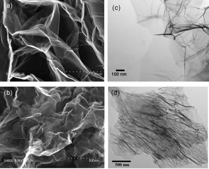
Table 4-1 Specific surface area of graphene and N-graphene determined by BET method. .. 59
Table 4-2 X-ray structural parameters of graphene and N-graphene from plane (002). ... 62
xvi
List of Figures
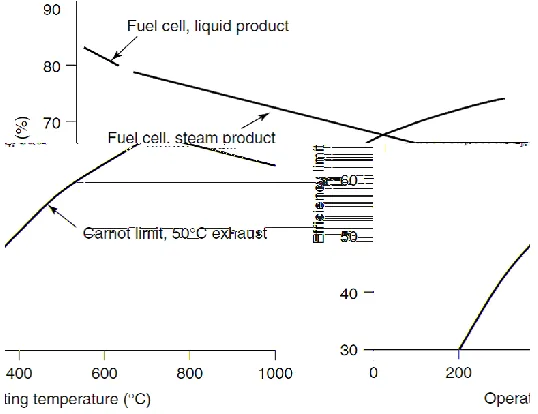
Figure 1-1 Maximum H2 fuel cell efficiency at standard pressure, with reference to higher heating value. The Carnot limit is shown for comparison, with a 50 oC exhaust temperature. 1
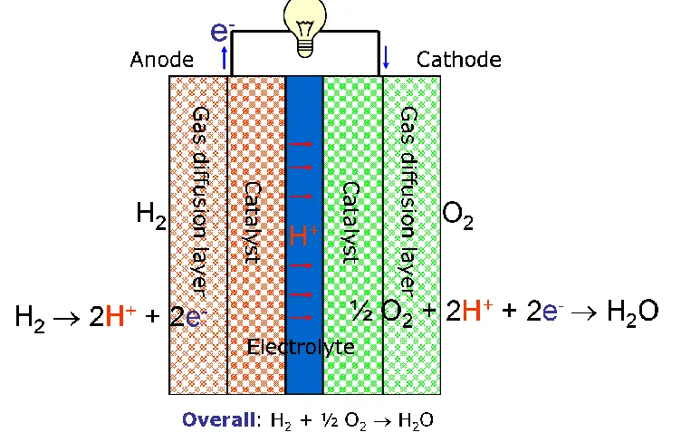
Figure 1-2 Schematic of the working principle for PEMFCs. ... 2
Figure 1-3 Low temperature fuel cell losses. ... 3
Figure 1-4 Pie chart of stack baseline cost... 4
Figure 1-5 Degradation processes of Pt nanoparticles on carbon support. ... 5
Figure 1-6 Summary of the progress over recent years with respect to transition metal oxide, carbide and nitride based materials as ORR electrocatalysts [56]. ... 9
Figure 1-7 Research topic of PEM fuel cell catalyst. ... 10
Figure 2-1 The schematic drawing of our synthesis stratagem of nitrogen doped carbon nanotubes. ... 21
Figure 2-2 The schematic process for graphene synthesis. ... 22
Figure 2-3 Schematic of CVD synthesis of N-graphene. ... 23
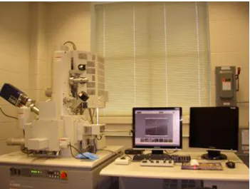
Figure 2-4 A photo of our SEM (Hitachi S-4800). ... 25
Figure 2-5 A photo of our TEM (Philips CM10). ... 26
Figure 2-6 Autolab potentiostat/galvanostat (Model, PGSTAT-30, Ecochemie, Brinkman Instruments) with rotation control (MSR, Pine Instruments). ... 28
Figure 2-7 Sketch of a rotating ring-disk electrode apparatus [11]. ... 28
xvii
saturated N2, 0.5 M H2SO4, room temperature). ... 31
Figure 3-1 (a) SEM image of CNx prepared with 200 mg of melamine; (b) the magnified images. ... 38
Figure 3-2 TEM images of CNx prepared with various amount of melamine: (a) 50 mg, (b) 200 mg, (c) 400 mg, (d) 2000 mg. ... 39
Figure 3-3 (a) Typical CV curves of CNx (7.7%) in 0.5 M H2SO4. Scan rate: 5 mVs-1; rotation speed: 900 rpm. (b) ORR polarization curves at a rotation speed of 900 rpm for the different CNx with the loading of 160 µg cm-2. ... 41
Figure 3-4 Oxygen reduction currents for CNx (7.7%) in 0.5 M H2SO4 with saturated O2. Scan rate: 5 mV s-1. ... 43
Figure 3-5 IDisk, IRing, n (the apparent number of electrons transferred during ORR), and %H2O2 measured by RRDE in O2 saturated H2SO4 at room temperature for CNx (7.7%). ... 43
Figure 3-6 Measured ORR currents of CNx (7.7%) catalyst at different electrode rotation speed (a) and different catalyst loading (b). Scan rate: 5 mV s-1, electrolyte: 0.1 M KOH. ... 45
Figure 3-7 The polarization curves of oxygen reduction on CNx catalysts with different nitrogen content. Electrolyte: 0.1 M KOH, scan rate: 5 mV s-1, and rotation speed: 1600 rpm. ... 47
Figure 3-8 RRDE voltammograms of CNx (7.7%) and Pt/C with different loading in 0.1 M KOH solution saturated with O2. The ring-disk electrode rotation rate was 1600 rpm, and the Au ring electrode was held at 0.7 V. ... 47
Figure 4-1 SEM and TEM images of graphene (a, c) and N-graphene samples (b, d)... 59
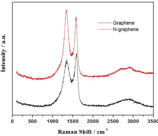
Figure 4-2 Raman spectra of graphene and N-graphene samples. ... 60
Figure 4-3 XRD patterns of graphene and N-graphene samples. ... 61
xviii
N1s spectra of N-graphene sample: The pink and black lines are the raw and fitted spectra. The red, green, and blue lines correspond to pyridine-like N (398.1 eV), pyrrole-like N (399.9 eV), and quaternary N (401.3 eV), respectively. ... 64
Figure 4-6 (a) and (b) TEY of the C K-edge and N K-edge XANES spectra of graphene and N-doped graphene, (c) FLY of the XANES spectra of the N-doped graphene, and (d) TEY of the O K-edge XANES spectra of graphene and N-doped graphene. ... 66
Figure 4-7 (a) Typical TEM image of graphene; (b) XPS survey scan spectra of
S-graphene; (c) Deconvoluted XPS spectrum of the S-2p-orbital for S-graphene. ... 73
Figure 5-1 The linear-sweep voltammograms of graphene and N-graphene under different temperatures. Electrolyte: O2-saturated 0.1 M KOH, scan rate: 5 mV s-1, and rotation speed: 1600 rpm. ... 78
Figure 5-2 The typical SEM (a) and TEM (b) images for N-graphene (900). (c) The Raman spectrum of graphene and N-graphene (900). (d) The XPS survey for three samples; (e) the high-resolution N1s spectrum for N-graphene: the black and purple lines are the raw and fitted spectra; the red, green, and blue lines correspond to pyridine-like N (398.1 eV),
pyrrole-like N (399.9 eV), and quaternary N (401.3 eV), respectively. ... 79
Figure 5-3 (a) Measured ORR currents of N-graphene (900) catalyst at different electrode rotation speed and (b) Koutecký-Levich plot at -0.5 V using the data obtained from (a). (c) and (d): The current density of ring and disk measured by RRDE for N-graphene (900). Scan rate: 5 mV s-1, electrolyte: 0.1 M KOH. ... 82
xix
graphene oxide nanoribbons; (d) the TEM of home-made CNx, and (e, f) the TEM images of
nitrogen doped graphene oxide nanoribbons. ... 91
Figure 6-2 The HRTEM images of (a) the pristine CNx and (b) nitrogen doped graphene
oxide nanoribbons. ... 92
Figure 6-3 The Raman spectra of MWCNTs and CNx. ... 93
Figure 6-4 (a) XPS spectra of CNx and NGON. (b) the high resolution N1s spectra of CNx
and NGON ... 94
Figure 7-1 (a), (b) SEM and TEM images of the synthesized NG. (c) A high-resolution TEM micrograph of NG. (d) Electron diffraction pattern of NG. ... 104
Figure 7-2 The high-resolution N1s spectrum for NG: the black and cyan lines are the raw and fitted spectra; the red and green lines correspond to pyridine-like N (398.5 eV) and quaternary N (401.3 eV), respectively. ... 105
Figure 7-3 (a) and (b): TEM images of Pt/NG and Pt/C (homemade). (c) CV curves of Pt/NG for the different cycles. Scan rate: 50 mV/s. (d) Normalized ECSA of Pt/NG, Pt/C
(homemade), and commercial Pt/C... 106
Figure 7-4 Raman spectra of NG and Vulcan XC-72. ... 107
Figure 7-5 Schematic description of NG formation process. ... 108
Figure 7-6 (a) SEM and (b) TEM images of Pt/graphene; (c) SEM and (d) TEM images of Pt/N-graphene. Graphene and N-graphene samples from Hummers’ method (please see Chapter 4), Pt nanoparticles deposition is done based on reference 24 in this chapter. ... 113
Figure 7-7 Cyclic voltammograms of: (a) Pt/C (E-TEK), (b) Pt/graphene, (c) Pt/N-graphene (2.8 at.% N) after 50, 500, 1000, 1500, 2000, 2500, 3000, 3500, 4000 cycles, and (d) the comparison of the degradations of the thee catalysts. Scan rate: 50 mV/s. ... 114
xx
(a) methanol (b) ethanol (c) ethylene glycol (d) formaldehyde. The insets are the
corresponding SAED pictures. ... 123
Figure 8-3 Normalized ECSA of urchin-like Pt nanostructures and commercial Pt/C. ... 124
Figure 8-4 TEM images of Pt nanostructures from the various reductants and under pH = 2: (a) methanol (b) formaldehyde (c) formic acid. ... 129
Figure 8-5 TEM images of Pt nanostructures from the various reductants under the existence of NO3- ([Pt]:[ NO3-] = 1 :10): (a) methanol (b) ethanol (c) 2-propanol (d) ethylene glycol (e) formaldehyde (f) formic acid. ... 130
Figure 8-6 TEM images of Pt nanostructures from the various reductants under the existence of Fe3+ ([Pt]:[ Fe3+] = 1 :10): (a) methanol (b) ethanol (c) 2-propanol (d) ethylene glycol (e) formaldehyde (f) formic acid. ... 131
xxi
List of Abbreviations
2D: two-dimensional
3D: three-dimensional
A
ADT: Accelerated durability test
B
BET: Brunauer, Emmett, and Teller
C
CNx: nitrogen doped carbon nanotubes
CV: Cyclic voltammograms
CVD: chemical vapour deposition
D
DOS: density of state
E
ECSA: electrochemical active surface area
F
FLY: fluorescence yield mode
FT-IR: Fourier transform-infrared
G
xxii
H
HRTEM: High-resolution transmission electron microscopy
I
ICP-OES: inductive coupled plasma-optical emission spectroscopy
K
K-L: Koutecky-Levich
M
MEA: Membrane electrode assembly
MOR: methanol oxidation reaction
MWNTs: multiwall carbon nanotubes
N
N-graphene: nitrogen doped graphene
NEXAFS: near-edge X-ray absorption fine structure
NGON: N-graphene oxide nanoribbons
NSTF: nanostructured thin film
O
ORR: oxygen reduction reaction
P
xxiii
RRDE: rotating ring disk electrode
S
SAED: selected area electron diffraction
SEM: scanning electron microscopy
SGM: Spherical Grating Monochrometor
SHE: standard hydrogen electrode
SWCNTs: single-wall carbon nanotubes
T
TEM: transmission electron microscopy
TEY: total electron yield
THH: tetrahexahedral
TPP: triphenyphosphine
TSA: toluenesulfonic acid
X
XANES: X-ray Absorption Near Edge Structure
XPS: x-ray photoelectron spectroscopy
Chapter 1
1
Introduction
1.1 Fundamentals of PEM fuel cells
Energy shortages and environmental pollution are serious challenges that humanity will face for the long-term. The world power demand is expected to double from 14 terawatts (TW) in the year 2000 to 28 TW by the year 2050 [1]. Fuel cells are innovative energy conversion devices that, with the help of catalysts, convert chemical energy to electrical energy [2]. As long as fuel is supplied, the fuel cell will continue to generate power. Since the conversion of the fuel to energy takes place via an electrochemical process, not combustion, the process is clean, quiet, and highly efficient-two to three times more efficient than fuel burning (see Fig.1-1) [3]. At about 200 oC, fuel cell can have 77% efficiency, whereas the efficiency limit is only is 30% for heat engine such as steam or gas turbines. Therefore, fuel cells have the potential to solve both energy crisis and pollution problems.
Figure 1-1 Maximum H2 fuel cell efficiency at standard pressure, with reference to
higher heating value. The Carnot limit is shown for comparison, with a 50 oC
Among various types of fuel cells [3], Proton Exchange Membrane Fuel Cells (PEMFCs) are attracting much more attention, and may, eventually, become a choice for power production due to their many advantages. They are all solid-state and compact, and can thus provide high power density. Their low operating temperature should also lead to quick start up and shut down. The tolerance of PEM fuel cells to the presence of CO2 is attractive in comparison with other fuel cells, which can also exhibit high power density and fast start up.
Membrane electrode assembly (MEA) is the heart of a single PEMFC, which consists of two electrodes (anode and cathode) and a separating proton exchange membrane (usually Nafion®). The schematic of MEA is shown in Fig.1-2. A stream of hydrogen is delivered
Figure 1-2 Schematic of the working principle for PEMFCs.
arriving through the external circuit to form water molecules. In the whole process, only electricity and water is produced. Therefore it is an environmentally friendly device. Each individual cell produces a voltage of about 0.6-0.7 V. To provide a suitable voltage, individual cells are stacked to form a fuel cell stack [4].
1.2 Challenges of PEM fuel cells
As introduced above, the oxygen reduction reaction (ORR) is the cathode reaction for PEMFCs. The oxygen reacts on the cathode side of the PEMFCs with protons and electrons to form water or hydrogen peroxide according to the half-cell redox process (eq. 1-1 and 1-2).
O2 + 4 H+ + 4 e- 2 H2O E0 = + 1.229 vs. NHE (eq. 1-1)
O2 + 2 H+ + 2 e- H2O2 E0 = + 0.695 vs. NHE (eq. 1-2)
The direct four electron process of oxygen reduction to form water is the preferred and desired reaction pathway. Hydrogen peroxide formation via direct two electron process is the competitive reaction and leads to significant cell voltage and overall efficiency losses in PEMFCs due to the sluggish rate limiting reaction [5]. Figure 1-3 showed the detailed
fuel cell losses, which can be broken up into four different types. These are activation losses, fuel crossover/internal current losses, ohmic losses, and mass transport/concentration losses. These losses each have a different effect on the theoretical voltage of the fuel cell [3]. To decrease the reaction rate loss, new developed and designed PEM fuel cell cathode catalysts need a maximum reducing of the hydrogen peroxide formation. Therefore, one of challenges for PEM fuel cells we are facing is still the activity of cathode catalysts. In addition, the higher cost is another barrier for the commercialization of fuel cell. Figure 1-4 shows the stack cost breakdown pie chart [6]. The electrodes represent approximately 77% of the fuel cell stack cost due to the most common, but expensive, platinum electrocatalyst. As the demand for Pt grows, the price of Pt has increased by almost three times from $520 per oz in 2002 to $1500 per oz in 2012 over the last decade [7]. Currently, the amount of platinum catalyst required per kilowatt to power a fuel cell engine is about 0.5 to 0.8 grams, or 0.018 to 0.028 ounces, which means the platinum catalyst alone would cost between $2,300 to $3,700 to operate a small, 100-kilowatt two- or four-door vehicle. To make the transition to fuel cell-powered vehicles possible, it is necessary to reduce the utilization of Pt and keep higher performance.
Another bottleneck problem in PEMFCs development is the limited electrochemical stability of the current catalysts (Pt nanoparticles supported on porous carbon). Figure 1-5 showed the detailed schematic for the degradation of Pt/C catalyst [8]. During the duty cycles of repeated start-ups and shut-downs, the fuel cell undergoes high potentials that lead to carbon and Pt degradation processes. Pt is dissolved and/or sintered into bigger agglomerates. Meanwhile, the agglomeration process is accelerated by carbon corrosion in oxidative conditions. As a consequence, Pt particles are detached from their support and tend to gather together, which results in the lower fuel cell performance. The degradation of Pt/C has been recognized as one of the main contributors to the long-term degradation of fuel cell performance [9-11].
Figure 1-5 Degradation processes of Pt nanoparticles on carbon support.
More durable, efficient, and inexpensive fuel cell electrocatalysts are desperately required before fuel cells can become commercially viable.
1.3 Solutions for catalyst development
activity and durability by changing catalyst particle, morphology and crystal structure; even alloy Pt with less expensive metals such as Fe, Co, Mn, Ni, Cu and others (II) looking for the novel support such as novel carbon supports, alternative carbon structures, and non-carbon supports (III) developing non-precious metal ORR catalyst.
1.3.1
Modifying Pt main catalyst
sites for O2 adsorption. Xia et al. developed Pd-Pt bimetallic nanodendrites consisting of a dense array of Pt branches on a Pd core, which are two and a half times more active on the basis of equivalent Pt mass for the ORR than the state-of-the-art Pt/C catalyst and five times more active than the first-generation supportless Pt-black catalyst due to relatively large surface areas and particularly active facets [23]. Adzic et al. demonstrated that platinum oxygen-reduction fuel-cell electrocatalysts can be stabilized against dissolution under potential cycling regime by modifying Pt nanoparticles with gold clusters [27].
1.3.2
Looking for the novel supports
Carbon black has been extensively used as a support for PEMFCs due to its fine properties and low cost. However, carbon black is known to undergo electrochemical oxidation to surface oxides and, finally, to CO2 at the cathode in the fuel cell, where it is subjected to low pH, high potential, high humidity, and high temperatures (~80 ºC). As carbon black corrodes, Pt supported on carbon black will detach from the electrode and possibly aggregate to larger particles, resulting in Pt surface area loss, which subsequently lowers the performance of PEMFCs [9, 28]. Therefore, many efforts have been made to develop more stable, high-surface-area carbon supports or other alternative carbon structures in an attempt to improve the durability of PEMFCs electrocatalysts [29]. Various carbon nanostructures such as single walled nanotubes [30], multiwalled nanotubes [31], stacked nanocups [32], graphitic nanofibers [33], graphene [34, 35], and mesoporous carbon materials [36] have been investigated as catalyst supports for PEMFCs. It has been shown that the structures and properties of the carbon supports, such as surface functional groups, graphitizing structure, and surface area, have a large effect on the activity and durability of the catalysts. The graphitic carbon (e.g. carbon nanotubes) is more stable than the conventionally used carbon black [37, 38]. In fact, Pt/carbon nanotubes have shown better performance and higher stability than Pt/carbon black due to the unique structure and properties of carbon nanotubes [31]. On the other hand, some metal oxides (TiOx, NbOx, etc.) even nanostructured crystalline organic
3M has developed nanostructured thin film (NSTF) catalyst technology platform [41]; the NSTF catalysts are formed by high volume capable vacuum sputter-deposition of polycrystalline thin film catalyst alloys onto a supported monolayer of oriented crystalline organic-pigment whiskers. The whisker support particles are immune to corrosion and eliminate the high voltage corrosion plaguing carbon supports. To date it might be the only practical example of an extended surface area catalyst, which has been shown to eliminate or significantly reduce many of the performance, cost and durability barriers standing in the way of cathodes and anodes for H2/air PEMFCs for vehicles.
1.3.3
Developing non-precious metal ORR catalyst
has the more important progress. Zelenay et al. developed an approach using polyaniline as a precursor to a carbon-nitrogen template for high-temperature synthesis of catalysts incorporating iron and cobalt [55]. The researchers found that fuel cells containing the carbon-iron-cobalt catalyst not only generated comparable currents with the output of precious-metal-catalyst fuel cells, but held up favorably when cycled on and off---a condition that can damage inferior catalysts relatively quickly. Another important contribution is the development of non-precious
Figure 1-6 Summary of the progress over recent years with respect to transition
metal oxide, carbide and nitride based materials as ORR electrocatalysts [56].
1.4 Objectives of thesis
Based on the above review, it is obvious that catalyst design is a key factor for enhancing the performance and realizing the commercialization of fuel cells. Surrounding the development of fuel cell catalysts, we will focus on the state-of-art mentioned above to develop new synthesis technology for 1D Pt, nitrogen doped carbon nanotubes, and 2D graphene-based materials, and investigate their electrochemical activity and durability. Figure 1-7 illustrates the separate research areas of this thesis. For Pt main catalyst, our
Figure 1-7 Research topic of PEM fuel cell catalyst.
group has proved that 1D Pt nanowires exhibited the higher ORR activity and durability than commercial Pt/C. But current methods for synthesis of Pt nanowires are either cumbersome or very difficult to scale up. The relative simple method to produce Pt nanowire at the large scale is always expected. In terms of support, the ideal support should have the following structure and properties: (i) high specific surface area, which is necessary for improving Pt dispersion, (ii) high electrical conductivity, (iii) low combustive reactivity under both dry and humid air conditions at low temperatures (150 o
science and applied research due to its various remarkable properties including the ultra-high surface area (calculated value, 2,630 m2g-1), high conductivity (resistivity: 10-6 Ω cm, less than the resistivity of silver, the lowest resistivity substance known at room temperature) and high chemical stability [58]. It is regarded as the basic building-block of carbon nanotubes and large fullerenes. All of the aforementioned properties combined with its unique graphitized basal plane structure and potential low manufacturing cost make it a promising candidate for catalyst support materials in PEMFCs. Recent work has shown that graphene used as Pt support has higher performance and higher Pt utilization over carbon black [34, 59] and higher stability [35]. However, Pt dispersion and size distribution have not been well controlled due to inert nature of graphene surface. Further investigation such as surface modification and doping other elements on graphene is desperately needed. As far as non-precious metal catalysts are concerned, we think that doping carbon materials should be good candidate. In general, chemical doping with N or B, P, S is considered an effective method to intrinsically modify the properties of carbon materials. Especially nitrogen doping plays a critical role in regulating the electronic and chemical properties of carbon materials due to its comparable atomic size and five valence electrons available to form strong valence bonds with carbon atoms. Theoretical study has shown that nitrogen doping results in the higher positive charge on a carbon atom adjacent to the nitrogen atoms [53], and a positive shift of Fermi energy at the apex of the Brillouin zone of graphene [60]. In our work, the promoting effect of nitrogen on the ORR activity was studied in detail by nitrogen doped carbon nanotubes (CNx) with the various nitrogen contents firstly. Also the aforementioned unique
properties of nitrogen-doped carbon materials and graphene promoted us to investigate the ORR activity of nitrogen-doped graphene, even boron, phosphor, and sulfur doped graphene.
1.5 Thesis structure
Chapter 1 gives an introduction to proton exchange membrane fuel cell, and the challenge of cathode materials, as well as the state-of-art solutions for the catalyst development. Importantly, the thesis objective and organization are also stated clearly.
Chapter 2 presents the detailed experimental process for synthesis, characterization, and performance test of nanomaterials, and provides all materials, apparatus, instruments used in the research.
Chapter 3 (Non-Noble Metal Oxygen Reduction Electrocatalysts Based on Carbon Nanotubes with Controlled Nitrogen Contents) reports the synthesis of nitrogen doped carbon nanotubes with the various nitrogen contents. The relationship between structures of CNx and ORR activity is investigated in detail. The active site involving nitrogen, iron,
carbon is further identified by the study. Most importantly, our best CNx electrocatalyst
has the similar ORR activity with a platinum-based catalyst with a loading of 1.94 microgram of platinum per square centimeter at the electrochemical window tested in alkaline solution, showing that CNx has the potential to replace the costly Pt/C catalyst in
alkaline fuel cells.
Chapter 4 (Nitrogen Doping Effects on the Structure of Graphene) gives a systematical investigation on the effects of N-doping on the structure of graphene by many characterization techniques especially XANES. Some interesting results have been obtained, such as more defects are present on nitrogen doped graphene, and N doping decreases the surface oxygen-containing groups.
Chapter 6 (Nitrogen doped graphene oxide nanoribbons from Nitrogen doped carbon nanotubes) makes an attempt to prepare nitrogen doped graphene with high aspect ratio. We obtained N-graphene oxide nanoribbons (NGON) using a simple solution-based oxidative process to unzip CNx. The study opens a new door to synthesize nitrogen doped
graphene at the large scale. The use of a low cost precursor and the solution-based procedure renders this method an attractive procedure to prepare NGON.
Chapter 7 (One-pot Solvothermal Synthesis of Doped Graphene with the Designed Nitrogen Type Used as a Pt Support for Fuel Cells) reports a large-scale preparation of nitrogen doped graphene by a novel solvothermal method featuring a lower synthesis temperature than previously reported. By the method, for the first time, nanoflower-like nitrogen doped graphene was obtained with pure sp2 hybridized carbon and we realized the controllable synthesis of designed nitrogen types. More importantly, the synthesized materials exhibit much higher durability as Pt support for fuel cells than commercial carbon powder. The synthesis concept we proposed should pave new ways for design of the doped graphene materials with the controllable doping, which is especially important for future research and development of carbon materials for fuel cells.
Chapter 8 (A universal method to synthesize urchin-shaped Pt nanostructures) reports a simple and versatile strategy for synthesizing flower-like Pt nanostructures made of 1D Pt nanowires. Compared with those reported methods previously, our method has the following main advantages: i) It can be conducted very efficiently, even at room temperature. ii) Without any surfactant or template, the products can be purified and collected easily. iii) The process is environmentally friendly. iv) The amount of product can easily be scaled up. Our work reveals that the simplest, natural method, often overlooked, may indeed yield exciting results in scientific research again.
Chapter 9 summarizes the results and contributions of the thesis work. In addition, the author gives some personal opinions and suggestions for future work.
References
[1] H.A. Gasteiger, S.S. Kocha, B. Sompalli, F.T. Wagner, Activity benchmarks and requirements for Pt, Pt-alloy, and non-Pt oxygen reduction catalysts for PEMFCs, Appl Catal B-Environ, 56 (2005) 9-35.
[2] R. O'Hayre, S.W. Cha, W. Colella, F.B. Prinz, Fuel cell Fundamentals, John Wiley & Sons, New York, 2006.
[3] J. Larminie, A. Dicks, Fuel Cell Systems Explained (second edition), John Wiley & Sons Ltd,, West Sussex, England, 2003.
[4] R. Borup, J. Meyers, B. Pivovar, Y.S. Kim, R. Mukundan, N. Garland, D. Myers, M. Wilson, F. Garzon, D. Wood, P. Zelenay, K. More, K. Stroh, T. Zawodzinski, J. Boncella, J.E. McGrath, M. Inaba, K. Miyatake, M. Hori, K. Ota, Z. Ogumi, S. Miyata, A. Nishikata, Z. Siroma, Y. Uchimoto, K. Yasuda, K.I. Kimijima, N. Iwashita, Scientific aspects of polymer electrolyte fuel cell durability and degradation, Chem Rev, 107 (2007) 3904-3951.
[5] J.K. Nørskov, J. Rossmeisl, A. Logadottir, L. Lindqvist, J.R. Kitchin, T. Bligaard, H. Jo´nsson, Origin of the Overpotential for Oxygen Reduction at a Fuel-Cell Cathode, J. Phys. Chem. B, 108 (2004) 7.
[6] E.J. Carlson, P. Kopf, J. Sinha, S. Sriramulu, Y. Yang, Cost Analysis of PEM Fuel Cell Systems for Transportation Subcontract Report NREL/SR-560-39104, (2005).
[7] http://www.platinum.matthey.com/cgi-bin/dynamic.pl?template=historical.
[8] F. Hasché, Activity, stability, and degradation mechanisms of platinum and platinum alloy nanoparticle PEM fuel cell electrocatalysts, Ph.D. Dissertation, Technische Universität Berlin, 2012.
[10] X.W. Yu, S.Y. Ye, Recent advances in activity and durability enhancement of Pt/C catalytic cathode in PEMFC - Part II: Degradation mechanism and durability enhancement of carbon supported platinum catalyst, J Power Sources, 172 (2007) 145-154.
[11] Y. Shao-Horn, W.C. Sheng, S. Chen, P.J. Ferreira, E.F. Holby, D. Morgan, Instability of supported platinum nanoparticles in low-temperature fuel cells, Top Catal, 46 (2007) 285-305.
[12] M.K. Debe, Electrocatalyst approaches and challenges for automotive fuel cells, Nature, 486 (2012) 43-51.
[13] F.J. Nores-Pondal, I.M.J. Vilella, H. Troiani, M. Granada, S.R. de Miguel, O.A. Scelza, H.R. Corti, Catalytic activity vs. size correlation in platinum catalysts of PEM fuel cells prepared on carbon black by different methods, Int J Hydrogen Energ, 34 (2009) 8193-8203.
[14] J. Buttet, Geometrical Structure of Metal-Clusters, Z Phys D Atom Mol Cl, 3 (1986) 155-157.
[15] Y.N. Xia, Y.J. Xiong, B. Lim, S.E. Skrabalak, Shape-Controlled Synthesis of Metal Nanocrystals: Simple Chemistry Meets Complex Physics?, Angew Chem Int Edit, 48 (2009) 60-103.
[16] J. Solla-Gullon, J. Vidal-Iglesias, J.M. feliu, Shape dependent electrocatalysis, Annu. Rep. Prog. Chem., Sect. C: Phys. Chem., 107 (2011) 263-297.
[17] N. Tian, Z.Y. Zhou, S.G. Sun, Y. Ding, Z.L. Wang, Synthesis of tetrahexahedral platinum nanocrystals with high-index facets and high electro-oxidation activity, Science, 316 (2007) 732-735.
[19] Z.W. Chen, M. Waje, W.Z. Li, Y.S. Yan, Supportless Pt and PtPd nanotubes as electrocatalysts for oxygen-reduction reactions, Angew Chem Int Edit, 46 (2007) 4060-4063.
[20] S.H. Sun, G.X. Zhang, D.S. Geng, Y.G. Chen, R.Y. Li, M. Cai, X.L. Sun, A Highly Durable Platinum Nanocatalyst for Proton Exchange Membrane Fuel Cells: Multiarmed Starlike Nanowire Single Crystal, Angew Chem Int Edit, 50 (2011) 422-426.
[21] C.J. Zhong, J. Luo, B. Fang, B.N. Wanjala, P.N. Njoki, R. Loukrakpam, J. Yin, Nanostructured catalysts in fuel cells, Nanotechnology, 21 (2010) 062001.
[22] V.R. Stamenkovic, B. Fowler, B.S. Mun, G.F. Wang, P.N. Ross, C.A. Lucas, N.M. Markovic, Improved oxygen reduction activity on Pt3Ni(111) via increased surface site availability, Science, 315 (2007) 493-497.
[23] B. Lim, M.J. Jiang, P.H.C. Camargo, E.C. Cho, J. Tao, X.M. Lu, Y.M. Zhu, Y.N. Xia, Pd-Pt Bimetallic Nanodendrites with High Activity for Oxygen Reduction, Science, 324 (2009) 1302-1305.
[24] Y.H. Bing, H.S. Liu, L. Zhang, D. Ghosh, J.J. Zhang, Nanostructured Pt-alloy electrocatalysts for PEM fuel cell oxygen reduction reaction, Chem Soc Rev, 39 (2010) 2184-2202.
[25] J. Greeley, I.E.L. Stephens, A.S. Bondarenko, T.P. Johansson, H.A. Hansen, T.F. Jaramillo, J. Rossmeisl, I. Chorkendorff, J.K. Norskov, Alloys of platinum and early transition metals as oxygen reduction electrocatalysts, Nat Chem, 1 (2009) 552-556.
[26] P. Strasser, S. Koh, T. Anniyev, J. Greeley, K. More, C.F. Yu, Z.C. Liu, S. Kaya, D. Nordlund, H. Ogasawara, M.F. Toney, A. Nilsson, Lattice-strain control of the activity in dealloyed core-shell fuel cell catalysts, Nat Chem, 2 (2010) 454-460.
[28] J.G. Liu, Z.H. Zhou, X.X. Zhao, Q. Xin, G.Q. Sun, B.L. Yi, Studies on performance degradation of a direct methanol fuel cell (DMFC) in life test, Phys Chem Chem Phys, 6 (2004) 134-137.
[29] Y.Y. Shao, J. Liu, Y. Wang, Y.H. Lin, Novel catalyst support materials for PEM fuel cells: current status and future prospects, J Mater Chem, 19 (2009) 46-59.
[30] G. Girishkumar, K. Vinodgopal, P.V. Kamat, Carbon nanostructures in portable fuel cells: Single-walled carbon nanotube electrodes for methanol oxidation and oxygen reduction, J Phys Chem B, 108 (2004) 19960-19966.
[31] C. Wang, M. Waje, X. Wang, J.M. Tang, R.C. Haddon, Y.S. Yan, Proton exchange membrane fuel cells with carbon nanotube based electrodes, Nano Lett, 4 (2004) 345-348.
[32] C. Kim, Y.J. Kim, Y.A. Kim, T. Yanagisawa, K.C. Park, M. Endo, M.S. Dresselhaus, High performance of cup-stacked-type carbon nanotubes as a Pt-Ru catalyst support for fuel cell applications, J Appl Phys, 96 (2004) 5903-5905.
[33] H. Tang, J.H. Chen, L.H. Nie, D.Y. Liu, W. Deng, Y.F. Kuang, S.Z. Yao, High dispersion and electrocatalytic properties of platinum nanoparticles on graphitic carbon nanofibers (GCNFs), J Colloid Interf Sci, 269 (2004) 26-31.
[34] B. Seger, P.V. Kamat, Electrocatalytically Active Graphene-Platinum Nanocomposites. Role of 2-D Carbon Support in PEM Fuel Cells, J Phys Chem C, 113 (2009) 7990-7995.
[35] Y.Y. Shao, S. Zhang, C.M. Wang, Z.M. Nie, J. Liu, Y. Wang, Y.H. Lin, Highly durable graphene nanoplatelets supported Pt nanocatalysts for oxygen reduction, J Power Sources, 195 (2010) 4600-4605.
[37] D.A. Stevens, M.T. Hicks, G.M. Haugen, J.R. Dahn, Ex situ and in situ stability studies of PEMFC catalysts, J Electrochem Soc, 152 (2005) A2309-A2315.
[38] J.J. Wang, G.P. Yin, Y.Y. Shao, Z.B. Wang, Y.Z. Gao, Investigation of further improvement of platinum catalyst durability with highly graphitized carbon nanotubes support, J Phys Chem C, 112 (2008) 5784-5789.
[39] G.R. Dieckmann, S.H. Langer, Comparisons of Ebonex (R) and graphite supports for platinum and nickel electrocatalysts, Electrochim Acta, 44 (1998) 437-444.
[40] K. Sasaki, L. Zhang, R.R. Adzic, Niobium oxide-supported platinum ultra-low amount electrocatalysts for oxygen reduction, Phys Chem Chem Phys, 10 (2008) 159-167.
[41] M.K. Debe, Novel catalysts, catalysts support and catalysts coated membrane methods, in: Handbook of Fuel Cells, 2010.
[42] R. Bashyam, P. Zelenay, A class of non-precious metal composite catalysts for fuel cells, Nature, 443 (2006) 63-66.
[43] N.A. Vante, H. Tributsch, Energy-Conversion Catalysis Using Semiconducting Transition-Metal Cluster Compounds, Nature, 323 (1986) 431-432.
[44] M. Lefevre, E. Proietti, F. Jaouen, J.P. Dodelet, Iron-Based Catalysts with Improved Oxygen Reduction Activity in Polymer Electrolyte Fuel Cells, Science, 324 (2009) 71-74.
[45] Y.J. Feng, N. Alonso-Vante, Nonprecious metal catalysts for the molecular oxygen-reduction reaction, Phys Status Solidi B, 245 (2008) 1792-1806.
[47] F. Jaouen, E. Proietti, M. Lefevre, R. Chenitz, J.P. Dodelet, G. Wu, H.T. Chung, C.M. Johnston, P. Zelenay, Recent advances in non-precious metal catalysis for oxygen-reduction reaction in polymer electrolyte fuel cells, Energ Environ Sci, 4 (2011) 114-130.
[48] R.Z. Yang, K. Stevens, J.R. Dahn, Investigation of activity of sputtered transition-metal (TM)-C-N (TM = V, Cr, Mn, Co, Ni) catalysts for oxygen reduction reaction, J Electrochem Soc, 155 (2008) B79-B91.
[49] Y.Y. Shao, J.H. Sui, G.P. Yin, Y.Z. Gao, Nitrogen-doped carbon nanostructures and their composites as catalytic materials for proton exchange membrane fuel cell, Appl Catal B-Environ, 79 (2008) 89-99.
[50] F. Jaouen, S. Marcotte, J.P. Dodelet, G. Lindbergh, Oxygen reduction catalysts for polymer electrolyte fuel cells from the pyrolysis of iron acetate adsorbed on various carbon supports, J Phys Chem B, 107 (2003) 1376-1386.
[51] P.H. Matter, E. Wang, M. Arias, E.J. Biddinger, U.S. Ozkan, Oxygen reduction reaction activity and surface properties of nanostructured nitrogen-containing carbon, J Mol Catal a-Chem, 264 (2007) 73-81.
[52] P.H. Matter, E. Wang, U.S. Ozkan, Preparation of nanostructured nitrogen-containing carbon catalysts for the oxygen reduction reaction from SiO2- and MgO-supported metal particles, J Catal, 243 (2006) 395-403.
[53] K.P. Gong, F. Du, Z.H. Xia, M. Durstock, L.M. Dai, Nitrogen-Doped Carbon Nanotube Arrays with High Electrocatalytic Activity for Oxygen Reduction, Science, 323 (2009) 760-764.
[54] Y.F. Tang, B.L. Allen, D.R. Kauffman, A. Star, Electrocatalytic Activity of Nitrogen-Doped Carbon Nanotube Cups, J Am Chem Soc, 131 (2009) 13200-13201.
[56] A. Ishihara, Y. Ohgi, K. Matsuzawa, S. Mitsushima, K. Ota, Progress in non-precious metal oxide-based cathode for polymer electrolyte fuel cells, Electrochim Acta, 55 (2010) 8005-8012.
[57] T.R. Ralph, M.P. Hogarth, Catalysis for Low Temperature Fuel Cells PART I: THE CATHODE CHALLENGES, Platin Met Rev, 46 (2002) 3-14.
[58] A.K. Geim, Graphene: Status and Prospects, Science, 324 (2009) 1530-1534.
[59] Y.C. Si, E.T. Samulski, Exfoliated Graphene Separated by Platinum Nanoparticles, Chem Mater, 20 (2008) 6792-6797.
Chapter 2
2
Experimental and characterization techniques
2.1 Experimental
2.1.1
Synthesis of carbon nanotubes with the controlled nitrogen
contents via a floating catalyst chemical vapour deposition
method
The floating catalyst chemical vapour deposition method (CVD) was applied to synthesize CNx [1]. Typically, ferrocene (Fe(C5H5)2) (100 mg, 98%, Aldrich) was placed at the entrance of the furnace in the quartz tube. Different amount of melamine (50, 200, 400, 800, and 2000 mg, 99+%, Aldrich) was placed beneath ferrocene as the nitrogen additive. A small piece of silicon wafer (1cm×3cm) with a 30 nm-thick aluminum buffer layer was located in the center of the oven. After the system was heated to 850 oC under Ar gas with a rate of 60 oC min-1, ethylene gas was introduced (Fig. 2-1). After 5 min, the furnace was heated to 950 oC. The melamine vapour was brought into the reaction chamber by the gas flow and it was pyrolyzed in the middle of the reaction chamber as the nitrogen additive. After 15 min, the ethylene gas was turned off and the system was cooled down to room temperature in the flowing Ar gas. The synthesized catalysts were marked as CNx (0%), CNx (1.4%), CNx (3.0%), CNx (5.1%), CNx (7.7%) based on the
different nitrogen contents, respectively.
Figure 2-1 The schematic drawing of our synthesis stratagem of nitrogen doped
2.1.2
Synthesis of graphene by modified Hummers’ method
Graphite powder was used as the starting material. Graphene was first prepared by the oxidation of graphite powder using the modified Hummers’ method [2, 3]. Typically, graphite powder (1 g) and sodium nitrate (0.75 g) were first stirred in concentrated sulphuric acid (37.5 mL) while being cooled in an ice water bath. Then potassium permanganate (4.5 g) was gradually added to form a new mixture. After 2 h in an ice water bath, the mixture was allowed to stand for five days at room temperature with gentle stirring. Thereafter, 100 mL of 5 wt% H2SO4 aqueous solution was added into the above mixture over 1 h with stirring. Then, 3 g of H2O2 (30 wt% aqueous solution) was also added to the above liquid and the mixture was stirred for 2 h. After that, the suspension was filtered and washed until the pH value of the filtrate was neutral. The as-received slurry is the so-called graphite oxide. Finally, the dried graphite oxide was heated at 1050 oC for 30 s under Ar to get graphene [4]. The schematic synthesis process is shown in Figure 2-2.
Figure 2-2 The schematic process for graphene synthesis.
2.1.3
Synthesis of nitrogen doped graphene
2.1.3.1
Ammonia treated method
Figure 2-3 Schematic of CVD synthesis of N-graphene.
2.1.3.2
Solvothermal method
A solvothermal route was employed in the synthesis as described below. Typically, 200 mg of pentachloropyridine was placed in a 25 mL Teflon-lined autoclave. Then appropriate amount of metallic potassium was cut into flakes and rapidly added to the autoclave in the glove box. The autoclave was sealed and heated to the desired temperature, where it was maintained for 10 h before it was cooled to room temperature naturally. The products, dark precipitates, were filtered out and washed with acetone, absolute ethanol and water in sequence, and were then dried in a vacuum at 80 oC for 4 h.
2.1.3.3
From nitrogen doped carbon nanotubes to N-graphene
Commercial carbon nanotubes from Aldrich Company were used as the precursor to form graphene oxide nanoribbon (GON). CNx (5.1% at. N) (home-made) was selected as the
above mixture over 1h with stirring. Then, 1 mL of H2O2 (30 wt% aqueous solution) was also added to the above liquid and the mixture was stirred for 2h. After that, the suspension was filtered and washed until the pH value of the filtrate was neutral. The as-received slurry is then sonicated to get the so-called GON and NGON.
2.1.4
Synthesis of S, P doped graphene
For sulphur-doped graphene, graphene was dispersed to acetone with toluenesulfonic acid (TSA) [6]. Regarding phosphor-doped graphene, graphene was dispersed to ethanol with triphenyphosphine (TPP) [7]. The slurries were stirred at room temperature until totally evaporating the solvent. Then the resulting products were dried at 100 oC and finally which were calcined at 900 oC with Ar protection for 1 hour. Thus, the S or P-containing graphene was obtained.
2.1.5
Synthesis of dendritic Pt nanostructures via a universal
chemical method
2.2 Characterization techniques
2.2.1
Physical characterization (SEM, TEM, XPS, XRD, BET, and
Raman spectra)
To fully understand physical and chemical properties of the samples, a variety of analytical techniques have been used in this thesis.
The morphologies of the samples were characterized by Hitachi S-4800 field-emission scanning electron microscopy (SEM) operated at 5.0 kV, Philips CM10 (transmission electron microscopy) TEM operated at 80 kV. The instruments are shown in figure 2-4, 2-5, respectively. High-resolution transmission electron microscopy (HRTEM) and selected area electron diffraction (SAED) were characterized by a JEOL 2010 FEG microscope operated at 200 kV.
Figure 2-4A photo of our SEM (Hitachi S-4800).
Figure 2-5 A photo of our TEM (Philips CM10).
function and Shirley background algorithm. The sensitivity factors were also taken into account when we did the quantitative analysis. Furthermore, the synchrotron-based X-ray Absorption Near Edge Structure (XANES) spectroscopy measurements were performed at the Canadian Light Source (CLS) on the High Resolution Spherical Grating Monochrometor (SGM) beamline for the CK-, NK-, and OK-edge spectra. This beamline uses a 45 mm planar undulator and three gratings to cover a photon energy region from 250 to 2000 eV. It offers an energy resolution greater than 5000 E/ΔE at energy below 1500 eV [9]. The beamline is capable of providing 1012 photons per second at 250 eV and exceeds 1011 photons per second up to 1900 eV at 100 mA. Spectra were recorded in the fluorescence yield mode (FLY) using a microchannel-plate detector and the total electron yield (TEY) mode measuring the sample current. All spectra were normalized to the intensity of the incident beam (I0), measured simultaneously as the current emitted from a gold mesh located after the last optical elements of the beamline.
2.2.2
Electrochemical characterization
The electrochemical characterizations of the catalysts were conducted in a standard three-compartment electrochemical cell using a glassy carbon (GC) rotating ring disk electrode (RRDE: d=5mm, Au ring (6.5mm i.d., 7.5mm o.d.)) setup on an Autolab potentiostat/galvanostat (Model, PGSTAT-30, Ecochemie, Brinkman Instruments) with rotation control (MSR, Pine Instruments) (as shown in Figure 2-6, 2-7). Usually, a Pt wire was used as the counter electrode and an Ag/AgCl (3 M NaCl) or Hg/HgSO4 (saturated K2SO4) was used as the reference electrode. For convenience, all potentials in this thesis are referenced to the standard hydrogen electrode (SHE). For carbon materials, a typical catalyst film was produced at the disk electrode according to the following procedure: 5 mg of CNx, or N-graphene was suspended in the solution (1080 μL ethanol
0.05 wt % Nafion alcoholic solution was further dropped on the electrode surface and heated again at 60°C to stabilize the electrocatalysts [10].
Figure 2-6 Autolab potentiostat/galvanostat (Model, PGSTAT-30, Ecochemie,
Brinkman Instruments) with rotation control (MSR, Pine Instruments).
2.2.2.1
Cyclic voltammetry
The electrodes were first pretreated to remove surface contamination by cycling the electrode potential between 0.05 and 1.2 V vs SHE at 50 mV s-1 for 50 cycles in nitrogen saturated electrolyte. 50 cycles should be enough to assure quasi-steady-state voltammograms. Then, the cyclic voltammetry measurements were conducted by cycling the potential between 0.05 and 1.2 V, with sweep rate of 50 mV s-1. For each sample, at least three tests were run under the same condition for obtaining its repeatability.
2.2.2.2
ORR using rotation ring-disk electrode
Cyclic voltammograms (CVs) were recorded by scanning the disk potential from 1.20 to 0.05 V (0.5 M H2SO4 solution) and from 0.4 to −1.0V (0.1M KOH solution) vs SHE at a scan rate of 5mVs-1. And the ring potential was maintained at 1.2 and 0.7 V vs SHE,
Figure 2-8 Analysis of a linear sweep voltammogram (Pt/C, 0.05 – 1.20 V vs. SHE, 5
respectively, for acid and alkaline solutions in order to oxidize any hydrogen peroxide produced. First, CVs were recorded at 5 mVs-1 using nitrogen atmosphere to obtain the background capacitive currents. Next, CVs were recorded using the oxygen-saturated electrolyte. The electrolyte solution was purged with oxygen for 30 min before commencing oxygen reduction on the disk electrode. All ORR test were performed with a rotating speed of 1600 rpm (rounds per minute). Figure 2-8 gives a typical analysis for linear sweep voltammogram of ORR. Usually, the ORR activity is evaluated by comparing the half-wave potential. The higher the half-wave potential, the higher the activity of the catalyst is [12, 13].
2.2.2.3
Accelerated durability test (ADT)
Figure 2-9 Analysis of cyclic voltammogram (Pt/C, 0.05 – 1.20 V vs. SHE, 50 mV s-1,
saturated N2, 0.5 M H2SO4, room temperature).
References
[1] H. Liu, Y. Zhang, R.Y. Li, X.L. Sun, S. Desilets, H. Abou-Rachid, M. Jaidann, L.S. Lussier, Structural and morphological control of aligned nitrogen-doped carbon nanotubes, Carbon, 48 (2010) 1498-1507.
[2] W.S. Hummers, R.E. Offeman, Preparation of Graphitic Oxide, J Am Chem Soc, 80 (1958) 1339-1339.
[4] H.C. Schniepp, J.L. Li, M.J. McAllister, H. Sai, M. Herrera-Alonso, D.H. Adamson, R.K. Prud'homme, R. Car, D.A. Saville, I.A. Aksay, Functionalized single graphene sheets derived from splitting graphite oxide, J Phys Chem B, 110 (2006) 8535-8539.
[5] H.B. Wang, T. Maiyalagan, X. Wang, Review on Recent Progress in Nitrogen-Doped Graphene: Synthesis, Characterization, and Its Potential Applications, Acs Catal, 2 (2012) 781-794.
[6] K. Kwon, S.A. Jin, C. Pak, H. Chang, S.H. Joo, H.I. Lee, J.H. Kim, J.M. Kim, Enhancement of electrochemical stability and catalytic activity of Pt nanoparticles via strong metal-support interaction with sulfur-containing ordered mesoporous carbon, Catal Today, 164 (2011) 186-189.
[7] J. Liu, H. Liu, Y. Zhang, R.Y. Li, G.X. Liang, M. Gauthier, X.L. Sun, Synthesis and characterization of phosphorus-nitrogen doped multiwalled carbon nanotubes, Carbon, 49 (2011) 5014-5021.
[8] L. Wang, Y. Yamauchi, Synthesis of Mesoporous Pt Nanoparticles with Uniform Particle Size from Aqueous Surfactant Solutions toward Highly Active Electrocatalysts, Chem-Eur J, 17 (2011) 8810-8815.
[9] http://exshare.lightsource.ca/sgm/Pages/Beamline.aspx.
[10] D.S. Geng, D. Matsuki, J.J. Wang, T. Kawaguchi, W. Sugimoto, Y. Takasu, Activity and Durability of Ternary PtRuIr/C for Methanol Electro-oxidation, J Electrochem Soc, 156 (2009) B397-B402.
[11] T. Okada, M. Kaneko, Electrochemical Methods for Catalyst Evaluation in Fuel Cells and Solar Cells, in: T. Okada, M. Kaneko (Eds.) Molecular Catalysts for Energy Conversion, Springer, 2009.
[13] Y. Takasu, N. Yoshinaga, W. Sugimoto, Oxygen reduction behavior of RuO2/Ti, IrO2/Ti and IrM (M : Ru, Mo, W, V) O-x/Ti binary oxide electrodes in a sulfuric acid solution, Electrochem Commun, 10 (2008) 668-672.
[14] J. Zhang, K. Sasaki, E. Sutter, R.R. Adzic, Stabilization of platinum oxygen-reduction electrocatalysts using gold clusters, Science, 315 (2007) 220-222.
[15] U.S. Department of Energy, The Department of Energy Hydrogen and Fuel Cells Program Plan, 2011.
Chapter 3
3
Non-Noble Metal Oxygen Reduction Electrocatalysts
Based on Carbon Nanotubes with Controlled Nitrogen
Contents
Dongsheng Genga, Hao Liua, Yougui Chena, Ruying Lia, Xueliang Suna,*,
Siyu Yeb, Shanna Knightsb
a
Department of Mechanical and Materials Engineering, University of Western Ontario, 1151 Richmond Street N., London, Ontario, Canada N6A 5B9
b
Ballard Power Systems Inc., 9000 Glenlyon Parkway, Burnaby, BC, Canada V5J 5J8
*To whom correspondence should be addressed. E-mail: [email protected]
Tel: +1-519-6612111, Ext. 87759, Fax: +1-519-6613020
A version of this chapter has been published in Journal of Power sources, 2011, 196, 1795-1801.
promising results; however, the promoting effect of nitrogen on the ORR activity has not been studied in detail with various nitrogen contents.
In this work, we conducted a systematic study on CNx system by preparing a series of
catalysts via a floating catalyst chemical vapor deposition method using precursors consisting of ferrocene and melamine to control the nitrogen content. The emphasis was mainly placed on study of the correlation between surface structure and the ORR activity in acid and alkaline solutions. Structure, morphology and composition of all CNx
catalysts were characterized by SEM, TEM, and XPS. These results indicated that the surface nitrogen content (up to 7.7 at%) increases with the increase of melamine used. Electrochemical data indicated that the higher the nitrogen content is, the higher the oxygen reduction activity. Especially, the results demonstrated that CNx (7.7%) has
similar ORR activity and selectivity with commercial Pt/C in alkaline solution. Therefore, nitrogen-doped carbon nanotubes may have the potential to replace the costly Pt/C catalyst in fuel cells in an alkaline solution.
Keywords: Oxygen reduction reaction, Nitrogen-doped carbon nanotubes, Proton