Scholarship@Western
Scholarship@Western
Electronic Thesis and Dissertation Repository
10-4-2013 12:00 AM
Numerical and Experimental Analysis of Retrofit System for
Numerical and Experimental Analysis of Retrofit System for
Light-Framed Wood Structures Under Wind Loading
Framed Wood Structures Under Wind Loading
Ryan B. Jacklin
The University of Western Ontario
Supervisor
Dr. Ashraf El Damatty
The University of Western Ontario
Graduate Program in Civil and Environmental Engineering
A thesis submitted in partial fulfillment of the requirements for the degree in Master of Engineering Science
© Ryan B. Jacklin 2013
Follow this and additional works at: https://ir.lib.uwo.ca/etd
Part of the Structural Engineering Commons
Recommended Citation Recommended Citation
Jacklin, Ryan B., "Numerical and Experimental Analysis of Retrofit System for Light-Framed Wood Structures Under Wind Loading" (2013). Electronic Thesis and Dissertation Repository. 1687.
https://ir.lib.uwo.ca/etd/1687
This Dissertation/Thesis is brought to you for free and open access by Scholarship@Western. It has been accepted for inclusion in Electronic Thesis and Dissertation Repository by an authorized administrator of
(Thesis format: Integrated Article)
by
Ryan B. Jacklin
Graduate Program in Engineering Science Department of Civil and Environmental Engineering
A thesis submitted in partial fulfillment of the requirements for the degree of
Master of Engineering Science
The School of Graduate and Postdoctoral Studies The University of Western Ontario
London, Ontario, Canada
ii Abstract
Past high speed wind events have exposed the vulnerability of the roof systems of existing
light-framed wood structures to the uplift forces resulting from high speed winds,
contributing greatly to economic and human loss. This research focuses on developing a
retrofit system to increase the uplift capacity of the roofs of these structures using numerical
and experimental techniques. The proposed system provides the uplift forces an alternate
load path to the ground, reducing the demand placed on the weak, nailed connections within
the structure. A three-dimensional finite-element model of a roof system of full-scale wood
structure has been developed. The model is compared to the results of a full-scale experiment
in both the linear and nonlinear ranges, proving the ability of the model to predict the
deflected shape of the structure. The numerical results identify the importance of considering
the nonlinear plastic damage that occurs to the roof-to-wall connection under realistic wind
loading. The validated numerical model is then extended to include the proposed retrofit
idea. A rigorous analysis of the behaviour of the structure after application is then carried
out. The model predicts that application of the retrofit system can increase the critical mean
hourly wind velocity from 38m/s to 50m/s. An experiment has been conducted, proving the
retrofit system is effective at increasing the uplift capacity of light-framed wood structures.
The results of the experiment have been used to validate the assumptions of the numerical
model, proving that the model captures the structural interaction between the retrofit and
truss systems.
iii
Co-Authorship Statement
This thesis has been prepared in accordance with the regulations for an Integrated-Article format
thesis stipulated by the School of Graduate and Postdoctoral Studies at the University of Western
Ontario and has been co-authored as:
Chapter Two: Finite-Element Modeling of a Light-Framed Wood Roof System
The initial numerical model was developed by A. Dessouki. Modifications to the numerical
model and the numerical analysis were completed by R. Jacklin under the supervision of Dr.
A. A. El Damatty. Drafts of the work were prepared by R. Jacklin and modifications were
completed under the supervision of Dr. A. A. El Damatty. A paper co-authored by R. Jacklin,
A. A. El Damatty and A. Dessouki will be submitted to the Journal of Wind and Structures
Chapter Four: Analysis and Optimization of a Retrofit System for Light-Framed Wood Structures under Wind Loading
The development and analysis of the numerical model were completed by R. Jacklin under
the supervision of Dr. A. A. El Damatty. Drafts of the work were prepared by R. Jacklin and
modifications were completed under the supervision of Dr. A. A. El Damatty. A paper
co-authored by R. Jacklin and A. A. El Damatty will be submitted to Journal of Structural
Engineering.
Chapter Five: Experimental Testing of a Retrofit System to Increase Uplift Capacity of Light-Framed Wood Structures
The experimental testing and the numerical analysis were completed by R. Jacklin under the
supervision of Dr. A. A. El Damatty. Drafts of the work were prepared by R. Jacklin and
modifications were completed under the supervision of Dr. A. A. El Damatty. A paper
iv
Acknowledgments
I would like to first thank Dr. El Damatty for his valuable guidance and expertise throughout
the years of working under his supervision. I would also like to thank The Natural Science
and Engineering Research Council of Canada (NSERC) and M. A. Steelcon Engineering
Limited for the financial support of the research, Wilbert Logan and Ryan Tang for their
assistance with the experimental program, Murray Morrison for sharing the experimental
data, my family and friends for their support, and my sister Joella for her valuable editing
v
Table of Contents
Abstract ... ii
Co-Authorship Statement... iii
Acknowledgments... iv
Table of Contents ... v
List of Tables ... x
List of Figures ... xi
Chapter 1: Introduction ... 1
1.1 General ... 1
1.2 Background ... 4
1.2.1 Numerical and Experimental Studies of Structural Behaviour ... 4
1.2.2 Current Technology and Building Code Development ... 6
1.2.3 Retrofitting Technology ... 8
1.3 Objectives of Study ... 10
1.4 Thesis Structure ... 12
1.4.1 Finite-Element Modeling of a Light-Framed Wood Rood Structure... 13
1.4.2 Parametric Study of Retrofit System for Light-framed Wood Structures under Uniform Uplift Load ... 13
1.4.3 Analysis and Optimization of a Retrofit System for Light-Framed Wood Structures under Wind Loading ... 14
1.4.4 Experimental Testing of a Retrofit System to Increase Uplift Capacity of Light-Framed Wood Structures ... 14
1.5 References ... 14
Chapter 2:Finite-Element Modeling of a Light-Framed Wood Roof Structure ... 17
2.1 Introduction ... 17
vi
2.3 Numerical Modeling of the Roof Structure ... 23
2.3.1 Interior Trusses ... 23
2.3.2 Gable Truss ... 24
2.3.3 Plywood Sheathing ... 25
2.3.4 Roof to Wall Connection ... 26
2.3.5 Roof Overhang ... 27
2.3.6 Boundary Conditions ... 27
2.3.7 Load Input Data ... 28
2.4 Validation of the Numerical Model ... 30
2.5 Analysis of Structural Behaviour ... 34
2.5.1 Analysis of the Tributary Area Method ... 34
2.5.2 Behaviour under Uniform and Non-uniform Load ... 36
2.5.3 Effect of Increased Gable End Stiffness on Sheathing Failures ... 40
2.6 Conclusions ... 41
2.7 References ... 42
Chapter 3: Parametric Study of Behaviour after Retrofitting Under Uniform Load ... 45
3.1 Introduction ... 45
3.2 Model Description ... 49
3.2.1 Roof Structure ... 49
3.2.2 Bearing Cables ... 51
3.2.3 External Cables ... 51
3.2.4 Rigid Bar ... 52
3.3 Typical Behaviour of the Structure with Retrofit System ... 52
3.3.1 Effect on Roof to Wall Connection Behaviour ... 53
vii
3.3.3 Effect on Sheathing Deflection and Shear Force ... 57
3.4 Parametric Study under Uniform Pressure Distribution ... 58
3.4.1 Details of the Parametric Study ... 58
3.4.2 Results of Parametric Study ... 60
3.5 Conclusions ... 70
3.6 References ... 72
Chapter 4: Analysis and Optimization of a Retrofit System for Light-Framed Wood Structures under Wind Loading ... 73
4.1 Introduction ... 73
4.2 Model Description ... 77
4.2.1 General Structural Geometry, Elements and Properties ... 78
4.2.2 Time History Load Application ... 80
4.2.3 Roof to Wall Connection ... 81
4.2.4 Wall System ... 82
4.2.5 Numerical Model of Retrofit System ... 83
4.3 Numerical Results ... 84
4.3.1 Comparison to the Experimental Results ... 85
4.3.2 Analysis of the Plastic Deformation ... 89
4.4 Parametric Optimization under a Non-uniform pressure distribution ... 91
4.4.1 Design wind speed and loading ... 92
4.4.2 Design Variables ... 92
4.4.3 Design Constraints ... 92
4.4.4 Results ... 94
4.5 Assessment of Optimized Retrofit under Non-uniform Pressure Distributions ... 96
4.5.1 Assessment Under Selected 35mps Time History ... 96
viii
4.6 Feasibility Analysis of Nylon Strap ... 102
4.6.1 General Discussion of Material Properties ... 102
4.6.2 Numerical Results ... 103
4.7 Conclusions ... 105
4.8 References ... 107
Chapter 5: Experimental Testing of a Retrofit System to Increase Uplift Capacity of Light-Framed Wood Structures ... 109
5.1 Introduction ... 109
5.2 Proposed Retrofit System ... 113
5.3 Experimental Design ... 116
5.3.1 Apparatus ... 117
5.3.2 Experimental Instrumentation ... 121
5.3.3 Procedure ... 123
5.4 Description of the Numerical Model of the Experiment ... 124
5.4.1 Truss System ... 124
5.4.2 RTW Connection ... 125
5.4.3 Retrofit System ... 125
5.4.4 Cable and Turnbuckle Numerical Properties ... 126
5.5 Experimental Results ... 126
5.5.1 Control Experiment ... 126
5.5.2 „Retrofit – New‟ Experimental Results... 128
5.5.3 „Retrofit – Damaged‟ Experimental Results ... 134
5.6 Numerical Response and Behaviour ... 136
5.6.1 Load-Deflection Behaviour of Truss System ... 136
5.6.2 Force Distribution between Load Paths ... 138
ix
5.8 References ... 144
Chapter6: Conclusions and Future Research ... 146
6.1 Summary ... 146
6.2 Key Findings of the Current Work ... 146
6.3 Recommendations for Future Work... 149
x
List of Tables
Table 2.1: Load case selection from 20m/s TLP experiment ... 29
Table 2.2: Load case selection from 25m/s TLP experiment ... 29
Table 2.3: Total uplift force transferred by the RTW connections of the east gable for load cases selected from 20m/s wind speed experiment ... 36
Table 2.4: Total uplift force transferred by the RTW connections of the east gable for load cases selected from 25m/s wind speed experiment ... 36
Table 3.1: Initially proposed dimensions for full-scale retrofit system ... 52
Table 3.2: Parametric study values ... 59
Table 4.1: Values considered for the design variables ... 92
Table 4.2: Demand to capacity ratios for the optimum solutions of the parametric study ... 95
Table 4.3: Maximum force and demand to capacity ratio for each component under 35mps time history loading ... 100
Table 4.4: Critical mean hourly wind velocities of numerical analysis (m/s) ... 104
Table 5.1: Initially proposed dimensions for full-scale retrofit system ... 116
Table 5.2: Summary of Experimental and Equivalent Full-scale properties ... 120
xi
List of Figures
Figure 1.1: Failure of roof sheathing above gable end, source: www.floridadisaster.org ... 3
Figure 1.2: Example of roof system failure after multiple RTW connection failures, source: www.Disastersafety.org ... 3
Figure 1.3: Elevation view of proposed retrofit system as applied to a gable-style roof ... 11
Figure 1.4: Elevation view of proposed retrofit system as applied to a gable-style roof ... 11
Figure 2.1: Full-scale experimental set-up with steel reaction frame ... 22
Figure 2.2: Plan view of pressure box distribution for the full-scale experiment ... 22
Figure 2.3: Plan view of structural skeleton of roof system ... 23
Figure 2.4: Elevation view and dimensions of interior Howe-style truss ... 24
Figure 2.5: Moment releases included in the finite-element model... 24
Figure 2.6: Gable end trusses of numerical model with additional external RTW connections ... 25
Figure 2.7: RTW connection load-deflection relationship ... 27
Figure 2.8: Pressure distribution for load case 5 (units = Pa) ... 29
Figure 2.9: Pressure distribution for load case 12 (units = kPa) ... 30
Figure 2.10: Deflection of the RTW connections for load case 5 ... 31
Figure 2.11: Deflection of the RTW connections for load case 12 ... 32
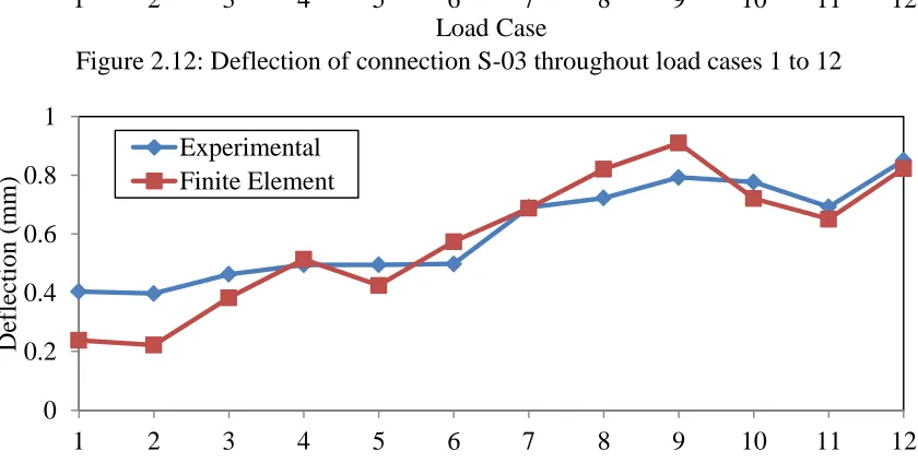
Figure 2.12: Deflection of connection S-03 throughout load cases 1 to 12 ... 33
Figure 2.13: Deflection of connection S-10 throughout load cases 1 to 12 ... 33
Figure 2.14: RTW connection force for tributary area method and numerical model, load case 12... 35
Figure 2.15: RTW deflections under equivalent uniform pressure distribution and realistic pressure distribution for load case 12 ... 37
Figure 2.16: Selection cuts for analysis ... 38
xii
Figure 2.18: Sheathing deflected profile along length of building at section 2-2 under
non-uniform and equivalent non-uniform pressure distribution for load case 12 ... 39
Figure 2.19: Predictions of uplift force per truss under non-uniform and equivalent uniform loading... 40
Figure 3.1: Elevation view of structure with retrofit system ... 47
Figure 3.2: Elevation view of structure with retrofit system ... 47
Figure 3.3: Plan view of proposed retrofit system as applied to a gable-style roof ... 48
Figure 3.4: Plan view of structural skeleton ... 50
Figure 3.5: Elevation view and dimensions of Howe-style truss... 50
Figure 3.6: Load deflection relationship for roof to wall connection ... 51
Figure 3.7: South elevation view with selected analysis points... 53
Figure 3.8: Typical applied uniform pressure vs selected RTW connection deflection ... 54
Figure 3.9: RTW connection deflection along the length of structure under 1.2kPa of uniform pressure ... 56
Figure 3.10: Typical bending moment diagram of center rigid bar under 1.2kPa of uniform pressure ... 57
Figure 3.11: Deflected shape of sheathing located above the center truss with and without the retrofit system under 1.2kPa uniform pressure ... 57
Figure 3.12: Resulting shear forces at selected sheathing locations with and without retrofit system under 1.2 kPa of uniform pressure ... 58
Figure 3.13: Applied pressure vs selected RTW connection deflection for varying external cable diameters... 61
Figure 3.14: Axial force in the bearing cables for varying external cable diameters under 1.6 kPa of uniform pressure ... 61
Figure 3.15: Applied pressure vs selected RTW connection deflection for varying bearing cable diameters... 62
Figure 3.16: Axial force in the bearing cables for varying bearing cable diameters under 1.6 kPa of uniform pressure ... 63
xiii
Figure 3.18: Axial force in the bearing cables for varying bar rigidities under 1.6 kPa of
uniform pressure ... 65
Figure 3.19: Applied pressure vs selected RTW connection deflection for insufficient initial external cable prestressing ... 66
Figure 3.20: Applied pressure vs selected RTW connection deflection for varying initial external cable prestressing ... 67
Figure 3.21: Axial force in the bearing cables for varying intial external cable prestressing under 1.6 kPa of uniform pressure ... 67
Figure 3.22: Applied pressure vs selected RTW connection deflection for varying external cable angle ... 68
Figure 3.23: Axial force in the bearing cables for varying external cable angles under 1.6 kPa of uniform pressure ... 69
Figure 3.24 Applied pressure vs selected RTW connection deflection for varying roof overhang lengths ... 70
Figure 4.1: Elevation view of proposed retrofit system as applied to a gable-style roof ... 76
Figure 4.2: Elevation view of proposed retrofit system as applied to a gable-style roof ... 76
Figure 4.3: Plan view of structural skeleton of roof system ... 79
Figure 4.4: Deflection of an experimental RTW connection during the 35m/s experiment ... 80
Figure 4.5: Developed load deflection response for roof to wall connection ... 82
Figure 4.6: Shifted and damaged experimental behaviour with loading ... 85
Figure 4.7: Deflected shape of the structure under maximum global uplift pressure (Time Step 633) ... 86
Figure 4.8: Deflected shape of the structure under minimum global uplift pressure (Time Step 116) ... 86
Figure 4.9: Experimental and numerical RTW connection deflection for truss 3 ... 88
Figure 4.10: Experimental and numerical RTW connection deflection for truss 9 ... 88
Figure 4.11: Experimental and numerical RTW connection deflection for truss 15 ... 88
Figure 4.12: Average magnitude of percent difference between experimental and numerical RTW connection deflections... 89
xiv
Figure 4.14: Deflected shape of the structure after damaging load, Time = 15 sec ... 91
Figure 4.15: Deflected shape of the RTW connections under the maximum loading ... 97
Figure 4.16: Deflection of the RTW connection S-03 through the time history ... 98
Figure 4.17: Section cut for analysis of deflected shape of the sheathing ... 98
Figure 4.18: Deflected shape of the sheathing under maximum loading ... 99
Figure 4.19: Deflection of the RTW connections under 38m/s wind loading ... 101
Figure 5.1: Elevation view of proposed retrofit system as applied to a gable-style roof ... 113
Figure 5.2: Elevation view of proposed retrofit system as applied to a gable-style roof ... 114
Figure 5.3: Plan view of proposed retrofit system as applied to a gable-style roof ... 114
Figure 5.4: Elevation view of the experimental apparatus with retrofit system ... 117
Figure 5.5: Elevation view of Experimental and Full-Scale Systems ... 118
Figure 5.6: Plan view of experimental and full-scale systems ... 119
Figure 5.7: Experimental setup ... 122
Figure 5.8: Experimental setup ... 122
Figure 5.9: Plan view of experimental apparatus with naming convention ... 123
Figure 5.10: RTW connection stiffness for developed for numerical model ... 125
Figure 5.11: Failure of connection W1-L3 after sudden withdrawal during control experiment ... 127
Figure 5.12: Load-deflection relationship for each RTW connections during control experiment... 128
Figure 5.13: RTW connection failure after application of retrofit system ... 129
Figure 5.14: Load-defection relationship for first connection failures during „Retrofit-New‟ and Control experiments ... 130
Figure 5.15: Load-deflection relationship of RTW connections of the „Retrofit-New‟ experiment... 130
Figure 5.16: Vertical component of force in each load path ... 133
xv
Figure 5.18: Axial force on external cables as external load applied ... 136
Figure 5.19: Load-deflection relationship for selected RTW connections, experimental results and numerical prediction... 137
Figure 5.20: Tensile force on external cables vs. load applied ... 139
Figure 5.21: Experimental result and numerical prediction for force in RTW connections as load is applied ... 140
Chapter 1
1
Introduction
1.1
General
The vast majority of structures in North America are residential. Light-framed wood
construction is preferred in this region due to the low cost, the availability of materials
and the ease of construction. Typical light-framed wood structures, which satisfy span
and load limits, follow the prescriptive requirements of governing building codes to
determine the member sizes and connection details. Most residential light-framed wood
structures meet these guidelines; consequently, structural analysis is not needed for the
design of these structures.
Past high speed wind events have exposed vulnerabilities in existing residential
light-framed wood structures, with the resulting damage being a major source of economic
loss. For example, the damage to light-framed wood structures represented a large portion
of the US$20-25 billion of economic losses caused by Hurricane Andrew in 1992 (HUD,
1993), with approximately 95% of those losses resulting from failure of components of
the roof system (Baskaran and Dutt, 1997). While light-framed wood structures
preformed much better during Hurricane Katrina in 2005, the lack of a continuous load
path from the roof to the foundation was still found to result in structural damage leading
to economic loss (van de Lindt et al., 2007 ). Pielke et al (2008) presented a normalized
analysis of hurricane damage over the last decade and found that increased population
and infrastructure in coastal regions could increase the economic loss caused by future
develop a mitigation technique that reduces the economic loss that result from damage to
light-framed wood structures in extreme wind events.
A major source of the economic loss caused by damage to light-framed wood structures
in extreme wind events, as identified by post hurricane damage reports, results from the
lack of a continuous load path from the roof to the foundation. Under the loading of high
speed wind, the roof system becomes subjected to uplift pressures generated in two ways.
First, as the air separates from the roof structure, a negative pressure is applied to the roof
sheathing. The second way by which roof uplift is generated occurs after a failure in the
building envelope on the windward wall. High internal pressures are then generated, add
to with the effect of the external negative pressure, resulting in large global roof uplift
pressures acting on the roof system. Under this uplift loading, the sheathing-to-truss
(STT) and the roof-to-wall (RTW) connections have been identified as weak links in the
load path of the structure (FEMA, 1993; van de Lindt et al., 2007). Both types of
connection rely on the withdrawal capacity of the nail to transfer the uplift forces to the
foundation. Complete structural collapse can occur as a result of either failure mode,
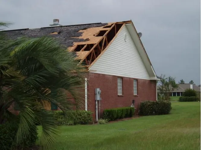
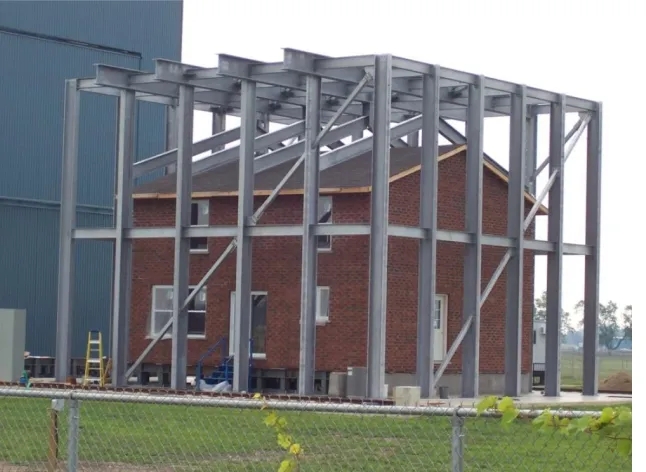
increasing economic loss and endangering the lives of the inhabitants. Figure 1.1 and
Figure 1.2 show examples of damage resulting to light-framed wood structures from STT
Figure 1.1: Failure of roof sheathing above gable end, source: www.floridadisaster.org
Figure 1.2: Example of roof system failure after multiple RTW connection failures, source: www.Disastersafety.org
The failures of previous structures suggest that the behaviour of light-framed wood
structures under uplift loading must be improved. As discussed below, past research has
experimental techniques, improving the strength of the individual connections with new
technologies and more stringent building codes, and developing retrofitting systems to
improve the strength of existing structures.
1.2
Background
1.2.1 Numerical and Experimental Studies of Structural Behaviour
In an attempt to better understand the behaviour of a light-framed wood structure,
numerous experimental and numerical studies have been conducted. The recent focus has
been full-scale, three-dimensional experimental and numerical work.
Morrison et al. (2012) loaded a full-scale structure built to the provisions of the Ontario
Building Code with a realistic pressure distribution. The loading, which was developed
from a wind tunnel study, was simulated using a system of 58 pressure bags, resulting in
a spatially and temporally varying roof sheathing pressure. They found that the structure
demonstrated significant load sharing, resulting in tributary area loads on the RTW
connections that were significantly above the failure loads anticipated from experiments
on individual toe-nail connections. Under the peak pressures of the realistic pressure
distribution, the RTW connections were found to suffer permanent withdrawal, becoming
increasingly damaged as the experimental loading progressed to higher wind velocities.
This connection damage was confirmed in the individual connection testing completed by
Morrison and Kopp (2011). The realistic wind loading applied during this study was
unique, as previous studies had focused on the behaviour of the toe-nail connection under
ramp loading. The testing of the individual connections found permanent withdrawal
the stiffness of the connection remained similar to that of the initial stiffness of the
connection.
Zisis and Stathopoulos (2012) studied the behaviour of an as-built, gable-style
light-framed wood structure under environmental loading. The structure was implemented with
load cells between the walls and foundation. Pressure taps on the structure and local
weather monitoring stations provided information about the magnitude of the applied
wind loading. The study found that approximately 30% of the total applied uplift force
was transferred through the gable walls to the foundation. The experimental study was
complemented with the dynamic analysis of a finite-element model consisting of frame,
area and rigid link elements. Due to the energy dissipation within the structure, the wind
load acting on the foundation was approximately 17 to 28% less experimentally than
predicted by the numerical model.
Shivarudrappa and Nielson (2013) developed a finite-element model of a gable roof
structure, validated using the experimental work of Datin and Prevatt (2013). Linear
frame and shell elements were used with nonlinear link elements to capture the behaviour
of the structure. The model was used to study the sensitivity of the distribution of the
applied load at the RTW connections on the properties of the materials and connections
within the structure. The sensitivity analysis found that the stiffness of the RTW
connections had a large effect on the load sharing behaviour of the structure. Increasing
the stiffness of the RTW connections reduced the amount of applied load shared to
surrounding trusses. Increasing the bending stiffness of the sheathing was found to
RTW connections created along the gable end truss reduced the forces acting on the
RTW connections of the next closest truss.
Li et al (1998) created a finite-element model of a truss system using the commercial
software ETABS. The trusses were modeled using frame elements with increased
bending stiffness for the top chord members to capture the partially composite behaviour
created by the sheathing. The behaviour of the sheathing was captured using beam
elements. The moment transferred by the gusset plate connection between truss members
was neglected. The developed model showed good agreement with the experimental
results presented in previous literature in terms of deflection, member axial force, and
load distribution.
In general, numerical and experimental studies of full-scale light-framed wood structures
have been completed to study their behaviour under uplift loading. The increased
understanding of the load sharing behaviour will result in better design practices, thereby
reducing the probability of failures in future structures.
1.2.2 Current Technology and Building Code Development
To address the capacity problems of the identified critical connections, product
development has occurred. An example of this is the “HurriQuake” nail, developed to
increase the capacity of the STT connection. The “HurriQuake” nail uses a harder shank
than a standard air nail to increase the reliability of truss penetration. The “HurriQuake”
nail also has a ring shank to increase withdrawal resistance, as well as a larger head
diameter. When testing sheathing panels connected to wood members using this nail, the
panels connected with 8d common nails (IHRC, 2012). Product development has also
addressed the issue of the capacity of the RTW connection. The truss tie (hurricane clip)
is a steel strap used to attach the truss to the top plate of the wall or the wall studs. This
strap complements the toe-nail connection, removing the withdrawal demand placed on
the nails. Available in many sizes, the tie can increase RTW connection uplift capacity to
7.6kN (Simpson Strong-Tie, 2008), approximately a 400% increase above that of a three,
16d toe-nail connection. Simpson Strong-Tie has developed steel ties for use throughout
the structure to create a continuous load path from the roof to the foundation. The use of
the “HurriQuake” nail and the steel straps to complement the nailed connections can
provide an efficient solution to the problems caused by uplift loading for new structures;
however, non-structural elements limit access to both the critical connections in existing
structures, making these technologies difficult to apply as a retrofit.
The issues in the capacity of the critical connections have also been addressed by
increasing the requirements of the building codes, which are constantly improving as
research and the lessons learned from extreme wind events identify the vulnerabilities of
the current version of the code. Major improvements were made to the South Florida
Building Code following Hurricane Andrew, increasing the capacity of both of the
critical connections discussed above. These changes were adopted locally in 1994 before
becoming standard for the entire state of Florida in 2001 (Gurley et al., 2006). Building
code changes have also occurred in Canada. For example, the most recent edition of the
National Building Code of Canada (NRC, 2010) defined high wind areas, in which the
capacity required for both the STT and the RTW connections are increased above that of
As code improvements are made, previously constructed buildings remain with known
vulnerabilities. Structures built before 1994 in the coastal regions of the United States are
extremely vulnerable to uplift forces caused by wind, as the majority use insufficient
nails for the STT connection (Datin et al., 2011). Thus, recent changes of building codes,
along with the known vulnerabilities of the structures constructed under previous editions
of those codes, suggests that a retrofit system capable of improving the uplift behaviour
of light-framed wood structures is needed.
1.2.3 Retrofitting Technology
While improved building codes have been found to reduce the number of failures
resulting from high speed winds in new structures (Meloy et al., 2007), existing structures
remain vulnerable. As a need has been identified, research has been conducted on the
development of retrofit techniques for light-framed wood structures.
Past attempts to develop retrofit techniques that have been presented in the literature have
focused on increasing the capacity of the individual critical connections. Datin et al
(2011) tested a sprayed polyurethane foam adhesive applied from within the structure to
the sheathing and truss members, reducing the withdrawal demand on the STT
connections. The experimental work found that the foam adhesive was effective at
increasing the uplift capacity of the roof sheathing by 250-300%. In another study,
Canbek et al (2011) investigated the use of a fiber reinforced polymer (FRP) tie to create
the RTW connection. Adhesives are used to bond the FRP tie to the top plate and the
truss to create the RTW connection. This technology is intended to replace or improve
the capacity of the current toe-nail or hurricane clip. The FRP tie provided 1.65 times
The previous two retrofit techniques require access to the critical connections for
installation, which can be costly due to the non-structural elements that are typically
installed in a residential home. Stewart et al (2003) presented an economic analysis of the
vulnerability of existing residential structures. They estimated that the cost of increasing
the hurricane resistance of a structure during construction ranges from 1-10% the cost of
the structure. This cost increases to 15-50% to retrofit a current structure, a large cost that
is a deterrent to many home owners.
Little technical research has been presented on a retrofit system which is economical,
easy to apply, and effective without modification to the existing structure; however,
patents have been issued on the subject. In general, these patents focus on a tension
element placed over the structure that is attached to ground anchors. These systems also
tend to include a pretensioning devise (ratchet or turnbuckle).
The patents issued for Bachynski (2007), Gaffney (1998), Gitlin and Maloney (1998),
and Watson Jr. (2008) all contain a retrofit system with a very fine fabric mesh placed
over the structure. The systems presented cover the entire roof of the structure, increasing
the capacity of both the STT and RTW connections. These harness systems also focus on
protecting the windows of the structure by continuing the fabric mesh to the ground to
protect the structure from flying debris, thereby maintaining the integrity of the building
envelope. While providing an effective retrofit system, the fine fabric mesh appears
difficult to apply to a structure quickly, resulting in a permanently installed system.
The patents issued to Bimberg and Bimberg(1997) and Luzzi (1999) contain systems
devices. In the system presented by Bimberg, a series of steel cables, connected to
wooden bearing pads, are applied over the roof of the structure and independently
connected to the ground. A more simple design is proposed by Luzzi. This patented
system is simply a nylon ratchet strap that is placed over the roof of the structure and
attached to the foundation using an anchoring device. While providing economic and
easy-to-apply retrofit techniques, these systems provide few tension members along the
roof, which can result in high local stresses on, and damage to, the fascia board of the
structure. Few tension members along the length of the roof would also reduce the ability
of the system to prevent failure of the sheathing. As the STT connection failure results in
a large amount of economic loss during high speed wind events, a system which reduces
the probability of this failure mode, while remaining inexpensive and easy to apply, is
necessary.
1.3
Objectives of Study
The objective of this research is to analyze the behaviour of a proposed retrofit system
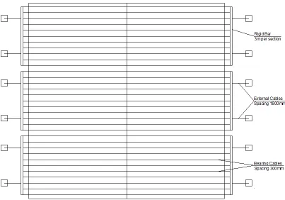
using numerical and experimental techniques. The proposed system consists of a series of
cables placed along the sheathing of the roof, identified as the bearing cables in Figure
1.3 and Figure 1.4. Along the eave of the structure, the bearing cables are attached to
rigid bars. Cables containing a prestressing device, identified as the external cables in
Figure 1.3 and Figure 1.4, connect the rigid bars to piles which are permanently installed
in the ground. When a high speed wind warning is announced, the system can be easily
applied to the roof of the building and attached to the piles. This system provides the
uplift forces an alternate load path to the ground without travelling through the weak
as applied to a gable-style roof. While similar in idea to the systems which have been
patented in the past, the inclusion of the rigid bar reduces the number of required ground
anchors. The rigid bar also works to provide a uniform distribution of force in the bearing
cable elements, reducing magnitude of local bearing forces acting on the structure. The
proposed system should provide improved capacity to both the STT and RTW
connections while being an easy to apply, cost effective system.
Figure 1.3: Elevation view of proposed retrofit system as applied to a gable-style roof
Figure 1.4: Elevation view of proposed retrofit system as applied to a gable-style roof
The adequacy of the retrofit system will be assessed as follows:
- Develop a three-dimensional, numerical model capable of capturing the behaviour
should match the full-scale experimental results obtained by Morrison et al.
(2012)
- Conduct an experimental program on a retrofitted section of a light-framed wood
structure to assess the ability of the retrofit system to increase the uplift capacity
of the roof structure.
- Use the experimental results to validate the assumptions of the numerical model
in terms of capturing the load distribution between the truss and retrofit systems.
- Conduct a numerical parametric study to understand the relationship between the
properties of the components of the retrofit system and the behaviour of the
structure.
- Determine the effect that varying the dimensions of each retrofit system
component has on the behaviour of the structure after retrofitting and the force
distribution within the retrofit system.
- Optimize the retrofit system to provide a minimum weight while satisfying
selected design constraints at a design wind speed.
- Assess the behaviour of the optimum retrofit system under multiple non-uniform
pressure distributions.
1.4
Thesis Structure
This thesis has been prepared in the integrated article format. This chapter provides the
motivation for the current work by discussing the vulnerability of light-framed wood
structures under uplift loads. A review is completed on past numerical and experimental
studies that focused on studying the behaviour of wood structures under uplift load. The
presented, including the development of new connection technologies and retrofit
techniques, as well as building code improvements. The objects of the thesis, which are
addressed in the following chapters, are clearly defined. Chapter six provides a summary
of the conclusions of this research, as well as suggestions for future work.
1.4.1 Finite-Element Modeling of a Light-Framed Wood Rood
Structure
Chapter two focuses on understanding the behaviour of light-framed wood structures
under uplift loading. A three-dimensional finite-element model capable of capturing the
behaviour of a light-framed wood structure under a realistic pressure distribution is
developed. The formulation of the numerical model is described, followed by validation
with a recently conducted full-scale experiment. After validation, the model is used to
analyze the behaviour of the truss system under realistic and equivalent uniform pressure
distributions and to perform an assessment of the use of the tributary area method to
calculate the withdrawal force resulting at each RTW connection.
1.4.2 Parametric Study of Retrofit System for Light-framed Wood
Structures under Uniform Uplift Load
Chapter three uses a developed numerical model to complete a parametric study on the
components of the retrofit system. This chapter begins with a description of the
developed numerical model. The model is used to study the typical behaviour of the
structure under a uniform pressure after application of the retrofit system. The results of
the parametric study are presented, with a focus on the effect that variation of each design
variable has on: a) the improvement of the structural behaviour resulting from application
1.4.3 Analysis and Optimization of a Retrofit System for Light-Framed
Wood Structures under Wind Loading
Chapter four begins by extending the developed numerical model of the light-framed
wood structure to include plastic damage at the RTW connection. After validation of the
model with the results of a full-scale experiment, the nonlinear model is used to assess
the behaviour of the proposed retrofit system under multiple non-uniform pressure
distributions. The components of the retrofit system are optimized to provide a minimum
weight while satisfying structural design constraints at a design wind speed. The optimal
system is then assessed under non-uniform pressure distributions to evaluate the increase
in capacity of the structure after application of the retrofit system.
1.4.4 Experimental Testing of a Retrofit System to Increase Uplift
Capacity of Light-Framed Wood Structures
Chapter five focuses on an experiment conducted to test the proposed system on a section
of roof. The idea of the retrofit system is first introduced, with a summary of the
numerical work previously completed. The results of the experiment are presented, with a
focus on the behaviour of the truss system after application of the retrofit system, as well
as the ability of the system to increase the capacity of the structure. The experimental
results are then used to validate the assumptions of the numerical model to gain
confidence in its adequacy.
1.5
References
Bachynski, M. (2007). U.S Patent No. 20070022672. Washington, DC: U.S. Patent and Trademark Office.
Bimberg, U., and Bimberg, O. (1997), U.S Patent No. 5623788. Washington, DC: U.S. Patent and Trademark Office.
Canbek, C., Mirmiran, A., Chowdhury, A., and Suksawan, N. (2011). Development of Fiber-Reinforced Polymer Roof-to-wall Connection. J. Compos. Constr., 15(4), 644-652.
Datin, P. L., Prevatt, D. O., and Pang, W. (2011). Wind-uplift capacity of residential wood roof-sheathing panels retrofitted with insulating foam adhesive. Journal of Architectural Engineering, 17(4), 144-154
Department of Housing and Urban Development (HUD). (1993). Assessment of Damage to Single-Family Homes Caused by Hurricanes Andrew and Iniki. U.S., Office of Policy and Development and Research, HUD-0006262.
Federal Emergency Management Agency (FEMA). (1993). Building Performance: Hurricane Iniki in Hawaii - Observations, Recommendations, and Technical Guidance.
Federal Emergency Management Agency.
Gaffney, G. (1998). U.S Patent No. 5819477. Washington, DC: U.S. Patent and Trademark Office.
Gitlin, H. M. and Maloney, Jr., J. W. (1998), U.S Patent No. 5791090, Washington, DC: U.S. Patent and Trademark Office.
Gurley, K., Davis, R.H., Ferrera, S.P., Burton, J., Masters, F., Reinhold, T., and
Abdullah, M. (2006). Post 2004 hurricane field survey – an evaluation of the relative performance of the Standard Building Code and the Florida Building Code.Proc. 2006 ASCE/SEI Structures Congress, St. Louis, MO. 8.
International Hurricane Research Center (IHRC). (2012). Hurricane loss reduction for housing in Florida: Roof Sheathing Fastener Study. Florida International University, Miami, USA.
Li, Z., Gupta, R., and Miller, T. H. (1998). Practical approach to modeling of wood truss roof assemblies. Practice Periodical on Structural Design and Construction, 3(3), 119-124.
Luzzi, J. (1999). U.S Patent No. 5881499. Washington, DC: U.S. Patent and Trademark Office.
Meloy, N., Sen, R., Pai, N., and Mullins, G. (2007). Roof damage in new homes caused by hurricane charley. Journal of Performance of Constructed Facilities, 21(2), 97-107.
Morrison, M. J., and Kopp, G. A. (2011). Performance of toe-nail connections under realistic wind loading. Engineering Structures,33(1), 69-76.
National Research Council of Canada (NRC). (2010). National Building Code of Canada (NBCC) 2010. Ottawa, NRCC 53301
Pielke, R. A., Gratz, J., Landsea, C. W., Collins, D., Saunders, M. A., and Musulin, R. (2008). Normalized hurricane damage in the united states: 1900-2005. Natural Hazards Review, 9(1), 29-42.
Shivarudrappa, R., and Nielson, B. G. (2013). Sensitivity of load distribution in light-framed wood roof systems due to typical modeling parameters. Journal of Performance of Constructed Facilities, 27(3), 222-234
Stewart, M. G. (2003). Cyclone damage and temporal changes to building vulnerability and economic risks for residential construction. Journal of Wind Engineering and Industrial Aerodynamics, 91(5), 671-691
Simpson Strong-Tie Company Inc. (2011). Technical Bulletin, Uplift Connectors, Truss-to-Wall Tiedowns (Spruce-Pine-Fir). Pleasanton, California.
van de Lindt, J., Graettinger, A., Gupta, R., Skaggs, T., Pryor, S., and Fridley, K. (2007). Performance of wood-frame structures during Hurricane Katrina. Journal of
Performance of Constructed Facilities, 21(2), 108-116.
Watson, Jr., A. (2006). U.S. Patent No. 7392620. Washington, DC: U.S. Patent and Trademark Office.
Chapter 2
2
Finite-Element Modeling of a Light-Framed Wood Roof
Structure
2.1
Introduction
Residential light-framed wood structures are very common in North America due to the
ease of construction, the low cost, and the availability of materials and labour.
Construction using of repetitive wood members, sheathing panels, and non-structural
elements results in a structure with a high degree of redundancy, as well as complex and
indeterminate load paths. Typical residential wood structures, subject to span and live
load limits, are not analyzed by an engineer. Instead member sizes and connections
details follow the prescriptive requirements of the local governing building code. Past
extreme wind events have exposed the vulnerability of this type of structure to the uplift
loading that results from high winds, with the sheathing-to-truss (STT) connections and
the roof-to-wall (RTW) connections being identified as the most critical connections in
the load path (FEMA, 1993; Shanmugam et al., 2009). The damage that resulted to
light-framed wood structures represented a large portion of the US$20-25 billion of economic
loss that was caused by Hurricane Andrew in 1992 (HUD, 1993). Approximately 95% of
this loss resulted from failures of materials of the roof system (Baskaran and Dutt,1997).
While light-framed wood structures preformed much better during Hurricane Katrina in
2005, the lack of a continuous load path from the roof to the foundation was still found to
result in structural damage leading to economic loss (van de Lindt et al., 2007 ).
As extreme wind events expose the vulnerabilities of existing structures, building codes
the National Building Code of Canada defined high wind areas, in which the capacities
required for both the STT and the RTW connections are increased above that of the
previous edition (NRC, 2010). Recent changes have also occurred to the Florida Building
Code. Major improvements were made to the South Florida Building Code following
Hurricane Andrew. These changes were adopted locally in 1994 before becoming
standard for the entire state of Florida in 2001 (Gurley et al., 2006). As building codes are
improved, existing structures remain with known vulnerabilities, as they are built to the
standard of an outdated code. Structures built before 1994 in the coastal regions of the
United States are extremely vulnerable to the uplift forces caused by wind as the majority
are constructed with insufficient nails for the STT connections (Datin et al., 2011). The
large economic loss that has occurred, the frequent building code changes, and the
vulnerability of existing structures all demonstrate the need to better understand the
behaviour of light-framed wood structures in high speed wind events.
In an attempt to better understand the behaviour of light-framed wood structures under
uplift loading, researchers have used a combination of experimental and numerical
studies. Morrison et al. (2012) loaded a full-scale structure built to the provisions of the
Ontario Building Code with a realistic pressure distribution. The loading, which was
developed from a wind tunnel study, was simulated using a system of 58 pressure bags,
resulting in a spatially and temporally varying roof sheathing pressure. They found that
the structure demonstrated significant load sharing, resulting in tributary area loads on the
RTW connections that were significantly above the failure loads anticipated from
experiments on individual toe-nail connections. Under the peak pressures of the realistic
becoming increasingly damaged as the experimental loading progressed to higher wind
velocities. This connection damage was confirmed in the individual connection testing
completed by Morrison and Kopp (2011). The realistic wind loading applied during this
study was unique, as previous studies had focused on the behaviour of the toe-nail
connection under ramp loading. The testing of the individual connections found that
permanent withdrawal occurred under the peak loads. During the unloading and reloading
phases after damage, the stiffness of the connection remained similar to that of the initial
stiffness of the connection.
Zisis and Stathopoulos (2012) studied the behaviour of an as-built, gable-style
light-framed wood structure under environmental loading. The structure was implemented with
load cells between the walls and foundation. Pressure taps on the structure and local
weather monitoring stations provided information about the magnitude of the applied
wind loading. The study found that approximately 30% of the total applied uplift force
was transferred through the gable walls to the foundation. The experimental study was
complemented with the dynamic analysis of a finite-element model consisting of frame,
area and rigid link elements. Due to the energy dissipation within the structure, the wind
load acting on the foundation was approximately 17 to 28% less experimentally than
predicted by the numerical model.
Shivarudrappa and Nielson (2013) developed a finite-element model of a gable roof
structure, which was validated using the experimental work of Datin and Prevatt (2013).
Linear frame and shell elements were used with nonlinear link elements to capture the
behaviour of the structure. The model was used to study the sensitivity of the distribution
connections within the structure. The sensitivity analysis found that the stiffness of the
RTW connections had a large effect on the load sharing behaviour of the structure.
Increasing the stiffness of the RTW connections reduced the amount of applied load
shared to surrounding trusses. Increasing the bending stiffness of the sheathing was found
to increase the load shared between trusses. The study also found that the additional
RTW connections created along the gable end truss reduced the forces acting on the
RTW connections of the next closest truss.
Li et al. (1998) created a finite-element model of a truss system using the commercial
software ETABS. The trusses were modeled using frame elements with increased
bending stiffness for the top chord members to capture the partially composite behaviour
created by the sheathing. The behaviour of the sheathing was captured using beam
elements. The moment transferred by the gusset plate connection between truss members
was neglected. The developed model showed good agreement with the experimental
results presented in previous literature in terms of deflection, member axial force, and
load distribution.
This chapter further investigates the behaviour of light-framed wood structures under the
uplift loading of a realistic pressure distribution. A three-dimensional finite-element
model is first developed to capture the behaviour of a full-scale experiment recently
conducted by at The University of Western Ontario. After describing the components
used to develop the numerical model, a comparison between the numerical prediction and
experimental results in terms of the deflected shape at the RTW connections is presented
to gain confidence in the numerical model. The model is then used to analyze the
distributions and to perform an assessment of the use of the tributary area method to
calculate the withdrawal force resulting at each RTW connection.
2.2
Description of the Conducted Experiment
An experiment has been recently conducted at the Insurance Research Lab for Better
Homes at the University of Western Ontario to study the behaviour of a light-framed
wood structure under a realistic wind pressure distribution. The tested structure, shown in
Figure 2.1, was built to the provisions of the Ontario Building Code and inspected to
ensure that it matched the typical construction techniques of the area. A realistic pressure
distribution was developed from a wind tunnel study and simulated using a system of 58
pressure bags, resulting in an applied pressure to the roof sheathing that varied in both
time and space. The pressure bags ranged from 0.36 m2 to 5.8 m2 in area. As shown in
Figure 2.2, the smallest bags were located at the windward edge of the structure, where
the largest variation in the magnitude of pressure occurs for the selected wind angle. The
magnitude of the realistic pressure distribution that was initially applied to the structure
corresponded to a mean wind velocity of 20 m/s at roof height. The wind velocity was
increased by 5 m/s until failure of the RTW connections, which occurred under the
pressure corresponding to a 45 m/s wind velocity. As the pressures were applied, the
resulting deflection at each RTW connection was recorded. Further details of the
Figure 2.1: Full-scale experimental set-up with steel reaction frame (source:
http://www.eng.uwo.ca/irlbh/)
2.3
Numerical Modeling of the Roof Structure
The experimental structure is numerically modeled using the finite-element program SAP
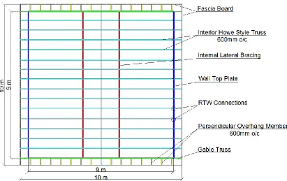
2000 (Computers and Structures, Inc., 2009). A plan view of the structural skeleton of the
roof system is provided in Figure 2.3, followed by a description of the various
components of the numerical model.
Figure 2.3: Plan view of structural skeleton of roof system
2.3.1 Interior Trusses
Linear frame elements are used to model the wood members of the truss system. The
structure contains 14 interior, Howe-style trusses spaced at 600mm (2ft) centers with the
dimensions shown in Figure 2.4. Top and bottom chords of the trusses are 39mm x 89mm
(2x4) members. Interior webbing of the trusses are constructed of 39mm x 64mm (2x3)
members. The material properties for the frame elements are provided by the Canadian
Figure 2.4: Elevation view and dimensions of interior Howe-style truss
Physical connections between the members within each truss are made with metal
“gusset” plates. Li et al (1998) conducted numerical modeling of a wood truss system and
concluded that, when compared to experimental literature, neglecting the moment
transfer of the gusset plate connection resulted in a more accurate force distribution
within truss members than a fully rigid, gusset plate connection. Moment is transferred
through a gusset plate when the member is continuous through the connection, as is the
case on the top and bottom chords of the truss. Figure 2.5 shows the locations of the
moment releases applied to the numerical model to capture the behaviour of the truss
described by Li et al (1998).
Figure 2.5: Moment releases included in the finite-element model
2.3.2 Gable Truss
The two exterior trusses, identified as the gable trusses in Figure 2.3, contain
modifications when compared to the interior trusses. Each gable truss has additional
continuously supported by an external wall, extra RTW connections are made along the
length of the truss. These connections result in the gable truss having a higher stiffness
than the interior trusses. As shown in Figure 2.6, additional vertical members are
included in the numerical model of the gable trusses to match the experimental structure,
with additional RTW connections at each location where a vertical member intersects the
bottom chord of the truss. Similar to the numerical formulation of the interior trusses,
moment releases are applied to each member of the gable trusses unless the member is
continuous through the gusset plate connection.
Figure 2.6: Gable end trusses of numerical model with additional external RTW connections
2.3.3 Plywood Sheathing
A total of 2112 shell elements are used to model the plywood sheathing of the roof. Shell
elements have membrane and bending capabilities allowing them to deform in and
out-of-plane, simulating the realistic behaviour of the sheathing. Each element has an
approximate area of .05 m2. The smallest pressure boxes in the full-scale experiment are
represented by 8 area elements in the finite-element model.
Wood is an anisotropic material, with strength dependent on the direction of the grains.
The stiffness of plywood sheathing is dependent on the layout of the grains of the plies.
To account for this, a modification factor is used to reduce the bending stiffness of the
by the CWDM. For 12mm CSP plywood constructed with 4 plies, the bending stiffness is
9 times larger in the direction of the face grains than that in the direction perpendicular to
the face grains (CWC and CSA, 2010). Thus, a factor of 0.11 is applied as an inertia
multiplier to reduce the bending stiffness of the shell element in this weak axis.
The plywood sheathing increases the bending stiffness of the top chord of the truss as
partially composite behaviour occurs and a “T” beam is created. To capture this
behaviour, the center line of the shell elements have been offset from the centerline of the
top chord of the truss. The nodes of the top chord are connected to the nodes of the
sheathing using a body constraint to model composite behaviour.
2.3.4 Roof-to-Wall Connection
A multi-linear force-deflection relationship, used to simulate the behaviour of the toe-nail
connection, is captured using a multi-linear elastic link element. A typical load-deflection
relationship for a toe-nail connection, as shown in Figure 2.7, is used in the numerical
model. This connection property has been adapted from the experimental work presented
by Reed et al. (1997), and is based on the average of 16 tests. The load deflection curve
has a high stiffness when subjected to a negative load, representing the truss bearing on
the top plate of the wall. Under withdrawal loading, the connection has an initial stiffness
Figure 2.7: RTW connection load-deflection relationship (adapted from Reed et al. 1997)
2.3.5 Roof Overhang
The roof system overhangs the top plate of the walls by approximately 500mm in each
direction. Figure 2.4 shows the construction method of the overhang in the direction
parallel to the trusses. The top chord of the truss continues past the RTW connection by
500mm, supporting the sheathing. The numerical model includes a fascia board, shown in
Figure 2.3, which is a 38mm by 89mm (2x4) member running perpendicular to the truss
system, connecting the free end of the overhang of each truss.
A 500mm overhang is included at each gable end. The roof sheathing is supported by
38mm by 89mm (2x4) members connected perpendicular to the gable truss, identified as
the perpendicular overhang members in Figure 2.3. A 38mm by 89mm (2x4) fascia board
running parallel to the top chord of the truss is attached to the outer edge of each 38mm
by 89mm (2x4) member. The fascia board supports the sheathing along the outermost
edge of the overhang around the entire structure.
2.3.6 Boundary Conditions
It is assumed that the walls beneath the RTW connections have negligible effect on the
deformation under the magnitude of loading applied. The wall system is neglected and
the boundary conditions of the numerical model are applied as deflection restraints
immediately beneath the top plate of the exterior walls.
2.3.7 Load Input Data
The comparison between the experimental and numerical results is carried out by
conducting quasi-static analysis. The natural period of the structure is well below the
critical periods of the loading, as such, the dynamic effect should have negligible effect
on the behaviour of the truss system. The nonlinear behaviour of the tested structure is
found to occur mostly at the RTW connections, where permanent, nonlinear damage
occurs as the peak pressures are applied. Before application of the first damaging peak
pressure, the behaviour of the connection can be approximated as linear elastic (Morrison
and Kopp, 2011). As such, the load cases considered for this analysis are selected before
the first damaging peak pressure so that nonlinear behaviour of the RTW connections is
not anticipated and quasi-static analysis is justifiable. Each selected load case is assessed
under a snap shot of the non-uniform pressure distribution, assuming no initial deflection.
To validate the numerical results at higher wind levels, after nonlinear damage to the
RTW connections has occurred, time-history analysis becomes necessary.
Twelve load cases have been selected from the experiment before damage occurred. The
loading of the selected time steps results in the largest global uplift forces applied to the
structure before the connections sustain damage. Table 2.1 and Table 2.2 show the time
steps selected from the full-scale experiment to validate the finite-element model. The
global uplift force acting on the structure is larger than the dead load of the roof
Table 2.1: Load case selection from 20m/s TLP experiment
Load Case 1 2 3 4 5 6
Time in TLP test (sec) 57.10 96.96 279.32 361.48 651.76 755.46
Global Uplift Force (kN) -21.3 -21.9 -22.3 -27.8 -22.0 -28.9
Table 2.2: Load case selection from 25m/s TLP experiment
Load Case 7 8 9 10 11 12
Time in TLP test (sec) 47.76 75.92 95.66 102.66 132.38 166.72
Global Uplift Force (kN) -30.2 -30.8 -34.5 -30.2 -30.7 -32.4
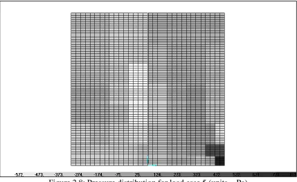
Two pressure distributions, load case 5 and load case 12, are shown below in Figure 2.8
and Figure 2.9, respectively. The distribution of pressure in load case 5 shows a strong
positive pressure in the windward corner, with a nearly uniform negative pressure applied
over the remainder of the structure. The distribution of pressure in load case 12 shows a
negative pressure applied over the entire roof system with stronger pressures above the
east gable end. Load case 12 results in the largest experimental deflections for the critical
connection before nonlinear damage initiates.
Figure 2.9: Pressure distribution for load case 12 (units = kPa)
2.4
Validation of the Numerical Model
The validation of the finite-element model includes a comparison between the numerical
predictions and the experimental full-scale test results in terms of deflection values at the
RTW connections. Each RTW connection is labeled as either a north or south link,
followed by the truss number. The windward corner is labeled connection N-01, with
numbers increasing along the length of the structure. Overhangs are labeled connections
N/S-01 and N/S-18. The gable ends are connections N/S-02 and N/S-17. The critical
connection during the experiment is identified as S-03.
For validation of the numerical model, the prediction of the deflected shape of the roof
should be similar to the full-scale experimental results. Variation of individual connection
magnitudes along the length is expected due to the variability of the toe-nail connection
properties. The deflection of the RTW connections along the north and south walls is
In terms of the deflected shape of the RTW connections along the length building, the
prediction of the numerical model shows good agreement with the experimental results.
For load case 5, in which the applied pressure is most uniformly distributed, the
numerical model predicts a nearly uniform deflected shape along the building. The
experimental results show more variability in the deflection of each connection. The
average deflection for the south side connections when the roof is subjected to the applied
pressure of load case 5 is 0.4mm for both the numerical prediction and the experimental
results. For the deflection of the north connections presented in Figure 2.10, the
numerical prediction and experimental results match very well in terms of average, with
both having a value of 0.2mm.
Figure 2.10: Deflection of the RTW connections for load case 5
Figure 2.11 shows the RTW connection deflection obtained under the applied pressure of
load case 12. Under this applied loading, the numerical prediction matches the
experimental results very well in terms of magnitude of deflection along the length of the
structure. Also, there is strong agreement in the trend of deflection for the connections
near the east gable on the south side. Both the numerical prediction and experimental
results predict that connection S-02, located on the gable truss, experiences less 0 0.1 0.2 0.3 0.4 0.5 0.6 0.7 0.8 S-0 1 S-0 2 S-0 3 S-0 4 S-0 5 S-0 6 S-0 7 S-0 8 S-0 9 S-1 0 S-1 1 S-1 2 S-1 3 S-1 4 S-1 5 S-1 6 S-1 7 N 09 N 10 N 11 N 12 N 13 N 14 N 15 N 16 N 17 D ef lec ti on (m m )
Roof to Wall Connection