Scholarship@Western
Scholarship@Western
Electronic Thesis and Dissertation Repository
8-23-2017 12:00 AM
Force Sensing Surgical Grasper with Folding Capacitive Sensor
Force Sensing Surgical Grasper with Folding Capacitive Sensor
Dave BP Tripp
The University of Western Ontario
Supervisor Dr. Michael Naish
The University of Western Ontario
Graduate Program in Electrical and Computer Engineering
A thesis submitted in partial fulfillment of the requirements for the degree in Master of Engineering Science
© Dave BP Tripp 2017
Follow this and additional works at: https://ir.lib.uwo.ca/etd
Part of the Biomedical Commons, and the Biomedical Devices and Instrumentation Commons
Recommended Citation Recommended Citation
Tripp, Dave BP, "Force Sensing Surgical Grasper with Folding Capacitive Sensor" (2017). Electronic Thesis and Dissertation Repository. 4854.
https://ir.lib.uwo.ca/etd/4854
This Dissertation/Thesis is brought to you for free and open access by Scholarship@Western. It has been accepted for inclusion in Electronic Thesis and Dissertation Repository by an authorized administrator of
Force Sensing Surgical Grasper with Folding Capacitive Sensor
Dave Tripp
M.E.Sc. Thesis, 2017
Department of Electrical and Computer Engineering
The University of Western Ontario
Abstract
Minimally-invasive surgery (MIS) has brought many benefits to the operating room, however,
MIS procedures result in an absence of force feedback, and surgeons cannot as accurately feel the
tissue they are working on, or the forces that they are applying. One of the barriers to introducing
MIS instruments with force feedback systems is the high cost of manufacturing and assembly.
The instruments must also be sterilized before every use, a process that can easily destroy any
embedded sensing system. An instrument that can be disposed of after a single use and produced
in bulk at a low cost is desirable.
Printed circuit micro-electro-mechanical systems (PCMEMS) is an emerging manufacturing
technology that may represent an economically viable method of bulk manufacturing small,
single-use medical devices, including surgical graspers. This thesis presents the design and realization of
a PCMEMS surgical grasper that can fit within a 5 mm trocar, and can accurately measure forces
in 3 axes, over a range of±4 N.
The designed instrument is the first PCMEMS grasper to feature multi-axis sensing, and has
a sensing range twice as large as current PCMEMS devices. Experimental results suggest that the
performance of the sensing system is similar to conventionally-manufactured MIS instruments that
use capacitive force transducers. The techniques applied in this thesis may be useful for developing
a range of PCMEMS devices with capacitive sensors. Improvements to the design of the grasper
and the sensing system are suggested, and several points are presented to inform the direction of
future work related to PCMEMS MIS instruments.
I feel very fortunate to have had Dr. Michael Naish as my MESc supervisor. Before I began my
MESc, I emailed him to discuss the possibility of pursuing other opportunities, and he provided
me with fair and honest advice. When I decided to return to Western he allowed me the freedom
to choose a thesis topic that interested me. I would like to thank him for his continued guidance
and support. Dr. Naish was always available to meet and discuss ideas, and at times was the only
person keeping me on track. Further, he always made sure I had the resources necessary to do
my work, including securing me good TA positions. His help was invaluable to the success of this
project.
The staff at CSTAR were always very welcoming, and allowed me to use CSTAR equipment
whenever I needed—including the computer that I typed this thesis on. I would especially like to
thank Abelardo (Abe) Escoto. Abe taught me how to use the Atometric micro milling machine,
and helped me through the difficulties of machining with 25 µm and 50 µm end mills. He was
a great source of information for all things related to MIS devices and helped fix many of my
poor designs for parts and fixtures. When I needed to use the wire EDM, or needed training or
assistance with any number of problems, Abe always made time to meet with me.
I like to think of the WearME group as our “sibling” lab. I would like to thank Dr. Trejos and
the WearME research group for letting me freely borrow tools or equipment.
The knowledge from the Electronics Shop in SEB is what brought my circuit designs to life:
Eugen Porter, Rob Barbeito, Trent Steensma, Ken Strong, and Ron Struke put in a lot of work
that helps the university and its students. Thank you for working with me when I needed to try
things that were new and difficult. Rob and Eugen helped me figure out the best way to make my
ACKKNOWLEDGEMENTS iv
laser printed flexible circuits, something that saved me a tremendous amount of time. Eugen was
a great source of ideas and problem solving solutions when I would stop in to discuss my (ongoing)
issues. He also always made time to 3D print pieces that I needed or run the laser cutter for me.
I would also like to thank Chris Vandelaar for all his guidance in machining and fabrication.
Chris was instrumental in my research and taught me the basics of CNC machining. He answered
many questions about the best way to fixture, machine, cut, and make everything from simple
to impossible parts. Chris saved me many hours by letting me know when I needed to abandon
certain ideas, and provided me with much better alternatives.
I’d like to thank my summer student Claire, who helped in the design and testing of the first
generation prototype, and was a source of good ideas and conversation. Thanks to my friend and
roommate Brandon Edmonds, for ensuring my time outside of the lab was well spent.
Finally, the financial support of the Natural Sciences and Engineering Research Council (NSERC)
Certificate of Examination i
Abstract ii
Acknowledgements iii
Table of Contents v
List of Figures viii
List of Tables x
Nomenclature and Acronyms xi
1 Introduction 1
1.1 Motivation . . . 1
1.2 General Problem Statement . . . 2
1.3 Research Objectives . . . 2
1.4 Scope . . . 3
1.5 Overview of the Thesis . . . 4
2 Literature Review 5 2.1 Introduction . . . 5
2.2 Force Sensing in MIS . . . 6
2.2.1 Is Force Sensing Needed? . . . 6
CONTENTS vi
2.2.2 Sensor Location . . . 8
2.3 PCMEMS . . . 9
2.3.1 Manufacturing PCMEMS . . . 10
2.3.2 PCMEMS Devices . . . 11
2.4 Force Sensing Medical Instruments . . . 20
2.4.1 Force Sensing Summary . . . 26
2.5 Capacitive Force Sensing Principles . . . 30
3 Design and Realization of the First Prototype 33 3.1 Introduction . . . 33
3.1.1 Manufacturing Notes . . . 33
3.1.2 Design Specifications . . . 34
3.2 Mechanical Design . . . 37
3.3 Sensing System Design . . . 41
3.3.1 Manufacture of the Circuit Boards . . . 44
3.4 Evaluation and Discussion—First Prototype . . . 44
3.4.1 Experimental Setup . . . 45
3.4.2 Experimental Results . . . 46
3.4.3 Experimental Discussion . . . 49
4 Design and Realization of the Second Prototype 50 4.1 Introduction . . . 50
4.2 Mechanical Design . . . 50
4.3 Sensing System Design . . . 52
4.3.1 Manufacture of the Circuit Boards . . . 55
4.4 Evaluation and Discussion—Second Prototype . . . 56
4.4.1 Experimental Setup . . . 56
4.4.2 Verification and Characterization of the Instrument . . . 58
4.4.2.1 Characterizing The Sensors . . . 58
4.4.2.3 Dynamic Response . . . 62
4.4.3 Force Transformation of Coupled Forces . . . 63
4.4.4 Noise and Resolution . . . 69
4.4.5 Temperature Response . . . 70
4.4.6 Mechanical Testing and Simulated Grasping Task . . . 71
4.5 Discussion . . . 72
4.5.1 Performance of the Sensing System . . . 72
4.5.2 Performance of Mechanical Components . . . 75
4.5.3 Concluding Remarks . . . 76
5 Conclusions and Future Work 77 5.1 Introduction . . . 77
5.2 Contributions . . . 78
5.3 Additional Outcomes . . . 79
5.4 Recommendations and Future Work . . . 80
List of Figures
2.1 Forces acting on minimally invasive instruments. . . 7
2.2 Alignment process for small chain [1]. . . 12
2.3 Self assembling PCMEMS hexagonal prism [1]. . . 13
2.4 Folding assembly of Mobee PCMEMS device. . . 14
2.5 PCMEMS minimally invasive surgical grasper. . . 15
2.6 Force sensing PCMEMS minimally invasive surgical grasper. . . 16
2.7 PCMEMS joints using expandable bladders. . . 17
2.8 Thumbscrew actuated jig for assembly scaffold of PCMEMS endoscopic wrist. . . . 18
2.9 PCMEMS force sensors. . . 19
2.10 Sterilizable force sensing instrument. . . 22
2.11 PVDF sensor design. . . 23
2.12 Capacitive shear sensor design principle. . . 24
2.13 Six-axis capacitive sensor by Lee et al. . . 25
2.14 Principles of operation of capacitive force sensing grasper. . . 26
2.15 Construction of capacitive force sensing grasper. . . 28
2.16 Capacitance changes under applied shear forces. . . 31
3.1 Fixture for micromilling machine. . . 35
3.2 Comparison of upper jaw designs under 5 N loads. . . 38
3.3 10:1 prototype paper model. . . 38
3.4 Completed sublaminate structures of first prototype. . . 39
3.5 Layers of each sublaminate. . . 40
3.6 Completed grasper with CAD model. . . 41
3.7 Expanded model of sensing circuit. . . 42
3.8 FPCB assembled with the grasper. . . 43
3.9 FPCB machined using the Atometric milling machine. . . 44
3.10 Testing setup for first prototype grasper. . . 45
3.11 Differential sensing of transverse shear sensors. . . 46
3.12 Response of axial shear sensor to 150 g and 250 g loads. . . 47
3.13 Sensor characterization of the left transverse shear sensor. . . 48
3.14 Dynamic loading of the right transverse shear sensor. . . 48
4.1 Sublaminate 1 modified for second version grasper. . . 51
4.2 Sublaminates 1 and 2 displaying plastic and castellated hinges. . . 51
4.3 Completed sublaminate structures of second-generation grasper . . . 52
4.4 Completed second-generation PCMEMS grasper. . . 53
4.5 Adhesive guide for MS910Med silicone. . . 54
4.6 FPCB manufacturing defects. . . 56
4.7 Sensor characterization testing setup. . . 57
4.8 Calibration curves for sensorized instrument. . . 59
4.9 Measurement of forces shown with error bars. . . 61
4.10 Dynamic response of axial sensor in negative direction. . . 62
4.11 Response to principle applied forces. . . 66
4.12 Relationship between sensors under an axial load. . . 67
4.13 Setup for heating the sensor using a 40 W incandescent light bulb. . . 70
4.14 Sensor response and drift under heat source. . . 71
4.15 Range of motion of grasper jaw. . . 72
List of Tables
2.1 Locations of force sensors for minimally invasive surgical instruments [2]. . . 9
2.2 Force sensing technologies . . . 29
3.1 Materials for body of grasper. . . 41
4.1 Typical properties of MS910 Med silicone adhesive. . . 54
4.2 FPCB manufacturing procedure using laser printer. . . 55
4.3 RMS error of sensors. . . 59
4.4 Repeatability of the sensing system. . . 60
4.5 Largest errors in each of the three sensors. . . 62
4.6 Dynamic response of axial sensor in negative direction. . . 63
4.7 Dynamic response of sensors. . . 63
4.8 Variable notation for coupled and applied forces. . . 64
4.9 Sensor coupling in response to loads applied purely in one axis. . . 65
4.10 Sensor noise for instrument. . . 69
4.11 Comparison of Kim grasper and PCMEMS grasper. . . 73
Acronyms
2D Two-Dimensional
3D Three-Dimensional
AC Alternating Current
AWG American Wire Gauge
CAD Computer-Aided Design
CDC Capacitance to Digital Converter
CFRP Carbon Fiber Reinforced Plastic
CNC Computer Numerically Controlled
CSTAR Canadian Surgical Technologies & Advanced Robotics
DOF Degree Of Freedom
DPSS Diode-Pumped Solid State
EDM Electrical Discharge Machining
FBG Fiber Bragg Grating
FEA Finite Element Analysis
FPCB Flexible Printed Circuit Board
GUI Graphical User Interface
IC Integrated Circuit
NOMENCLATURE AND ACRONYMS xii
LED Light Emitting Diode
MEMS Micro-Electro-Mechanical Systems
MFI Micromechanical Flying Insect
MIS Minimally Invasive Surgery
MMM Micro Milling Machine
PC Personal Computer
PCB Printed Circuit Board
PCMEMS Printed-Circuit MEMS
PDMS Polydimethylsiloxane
PVDF Polyvinylidene Fluoride
RMS Root Mean Square
rpm revolutions per minute
SL1 Sublaminate 1
SL2 Sublaminate 2
SL3 Sublaminate 3
USP United States Pharmacopeia
UV Ultraviolet
Variables
A Overlapping area between electrodes
δA Change in overlapping area between electrodes
C Capacitance
CA0 Adjusted axial capacitance response
CA Axial sensor capacitance response
CA,T Transverse coupled response on axial load
CN0 Adjusted normal capacitance response
CN Normal sensor capacitance response
CN,A Axial coupled response on normal load
CN,T Transverse coupled response on normal load
CT0 Adjusted transverse capacitance response
CT Transverse sensor capacitance response
CT,A Axial coupled response on transverse load
CT,N Normal coupled response on transverse load
E Young’s modulus
EA Equation of force response for axial sensor
EN Equation of force response for normal sensor
ET Equation of force response for transverse sensor
FA Force response of axial sensor
FN Force response of normal sensor
FT Force response of transverse sensor
ε0 Relative permittivity of air
εr Relative permittivity of dielectric
F Force
G Shear modulus
γ Shear strain
L Width of capacitive electrode
t Distance between electrodes in capacitor
∆t Change in distance t
τ Shear force
NOMENCLATURE AND ACRONYMS xiv
xs Linear displacement of electrode
Units
◦C degrees Celsius
cm centimeters
dB decibels
g grams
Hz hertz
N newtons
Nm newton-meters
Nmm newton-millimeters
min minutes
mil 0.001 inches
mg milligrams
mm millimeters
mN millinewtons
mV millivolts
µm micrometers
Ω ohms
pF picofarad
psi pounds per square inch
s seconds
V volts
Introduction
1.1
Motivation
Minimally invasive surgery (MIS) is a surgical technique performed through small incisions in the
body. Compared to traditional open surgery, MIS offers many benefits including reduced blood
loss, less pain, lower infection rates, shorter hospital stays, as well as high patient satisfaction and
improved cosmesis [2–4]. The drawbacks of MIS are also well noted: a steeper learning curve,
increased equipment costs, and a lack of force feedback.
Without force feedback, surgeons must rely on visual cues to determine tissue characteristics
and estimate the amount of force that they are applying. Surgeons perform many procedures
with limited or no force feedback—with a high rate of success—but there is plenty of evidence to
support the benefits of force feedback: when tying knots for suturing, three studies have shown
force feedback allows surgeons to be more consistent and tie tighter knots without breaking the
thread [5–7]; force feedback also improves the accuracy of palpation tasks [8]; and without force
feedback errors in a blunt dissection task increased by a factor of three [9].
One of the barriers to introducing force feedback in MIS instruments is the high cost of
man-ufacturing and assembly. The instruments must also be sterilized before every use, a process that
can easily destroy any embedded sensing system. Therefore, an instrument that can be disposed
of after a single use and produced in bulk at a low cost is desirable.
A relatively new technology known as printed circuit micro-electro-mechanical systems (PCMEMS)
1.2 General Problem Statement 2
has shown promise for creating devices that are small, complex, and inexpensive. Several PCMEMS
medical devices have been developed, including MIS graspers [10–16]. PCMEMS is well suited for
developing medical devices, however the current designs of MIS graspers only measure forces in
one axis, and are designed for a small force range (±1.5 N) [11].
The availability of a more robust PCMEMS grasper that offers a larger measurement range
and can measure forces in 3 axes would help to progress towards commercially viable PCMEMS
medical devices, as well as single use medical devices. The development of a commercially viable
force sensing surgical grasper must be considered from many different perspectives—this thesis
aims to explore one of these.
1.2
General Problem Statement
MIS instruments that accurately measure forces can provide a benefit to many surgical procedures;
however, the cost of these instruments must be low enough to justify widespread adoption.
Rea-sonable cost is achieved through devices that can be reprocessed and sterilized, or disposed of after
a single use. Sterilization and multiple uses often degrade performance when using force sensors,
and conventional manufacturing techniques usually fail to produce MIS instruments that perform
well enough, and are inexpensive enough for a single use.
PCMEMS is an emerging manufacturing technology that may be an economically viable
method of bulk manufacturing small, single-use medical devices, including surgical graspers.
How-ever, improvement to the function of PCMEMS surgical graspers is required before they can be of
clinical use. This thesis aims to contribute to the development of single-use disposable graspers
by creating a PCMEMS grasper with greater functionality than exists in current literature, and
by reducing barriers to fabricating PCMEMS devices.
1.3
Research Objectives
The primary goal of this thesis is to improve the development of MIS PCMEMS devices by
ex-panding on PCMEMS fabrication techniques and developing a PCMEMS grasper with greater
reach this goal.
• Explore layer fabrication methods other than laser-cutting machines normally used in PCMEMS,
to reduce barriers for researchers who may not have access to this equipment.
• Include three-axis force sensing in the grasper—researching various sensing modalities to
determine which are best suited for PCMEMS devices.
• Design, build, and evaluate a PCMEMS MIS grasper that has three-axis force sensing over
a range of ±4 N and can fit through a 5 mm trocar.
1.4
Scope
Many force sensing MIS graspers have been presented in literature, with many more in
develop-ment. The focus of this thesis is not to create the most robust or functional MIS grasper, but
to create the most robust and functional PCMEMS MIS grasper. Only PCMEMS manufacturing
techniques will be considered, and the thesis will focus only on creating a grasper small enough
to fit through a 5 mm trocar—a size suitable for arthroscopic surgery. To justify the development
of the grasper, the completed device should be comparable in function and form to existing force
sensing graspers, as determined through the state of the art. A small section of the thesis will be
devoted to showcasing the benefits of force feedback in MIS, and the advantages of locating sensors
at the tool tip (a benefit of using PCMEMS). Further justification of the benefits of PCMEMS will
be explored strictly from a literature review perspective—no independent experiments to explore
the advantages of PCMEMS manufacturing will be performed. This thesis requires the
develop-ment of a mechanical structure and layer designs for the PCMEMS device, such that the device
can pop-up and be assembled easily, and the development of a complete sensing system. Previous
PCMEMS graspers have been developed that measure forces in 1 axis only; the sensing system for
this grasper will feature 3 axes of force sensing. The grasper will be evaluated on the useful range,
1.5 Overview of the Thesis 4
1.5
Overview of the Thesis
The structure of the remainder of the thesis is as follows:
Chapter 2 Literature Review: Summarizes the state of the art for PCMEMS technology and current force sensing MIS graspers. Provides background information on the benefits of force feedback in minimally invasive surgery.
Chapter 3 First Prototype: Details the work done for the development and
manufacturing of the first-generation grasper. Includes the evaluation and discussion of this version of the instrument.
Chapter 4 Second Generation Grasper: Describes the changes and improvements made for the design and fabrication of the second-generation grasper. The design is evaluated and the results are discussed.
Literature Review
2.1
Introduction
The primary goal of the research was to further explore the use of printed-circuit MEMS (PCMEMS)
manufacturing to create a force sensing surgical instrument suitable for minimally invasive surgery.
Expanding on existing research to create an instrument using new techniques and materials, with a
larger force sensing range than current PCMEMS devices. To first ensure that the designed grasper
is a useful development, Section 2.2 provides a brief overview on when and how force sensing in
minimally invasive surgery is advantageous. Section 2.3 then discusses the process and capabilities
of PCMEMS, and why this may be useful for a MIS device. Examples of existing PCMEMS
de-vices are discussed, as well as general manufacturing guidelines. In Section 2.4, technologies used
for sensing forces are summarized. These technologies were reviewed for their relative usefulness,
but also for how well they can be incorporated into a PCMEMS device. A perceived advantage of
PCMEMS is inexpensive bulk manufacturing and efficient assembly when compared to traditional
manufacturing techniques—sensing methods that eliminate or reduce these advantages are
consid-ered in less detail. The chosen sensing modality for the instrument—capacitance based sensing—is
then explored in greater depth in Section 2.5.
2.2 Force Sensing in MIS 6
2.2
Force Sensing in MIS
It is intuitive to think that limiting the sense of touch, which is so heavily relied on by surgeons,
could be very detrimental to surgical outcomes. However many MIS procedures are currently
performed with limited or removed haptic feedback, with a high rate of success. Every process has
room for improvement though, and gains in intuitiveness or safety would justify the use of haptic
feedback. Therefore, the question to ask isn’t whether we need haptic feedback to successfully
perform a surgery, but what improvements may result from including haptic feedback. This section
examines the challenges of measuring forces during MIS procedures, and how force sensing may
add value in surgery.
2.2.1 Is Force Sensing Needed?
To understand if force sensing is needed, it is important to look at some factors that can cause
errors between perceived and actual forces in surgery. In traditional MIS, a trocar is placed through
a small incision in the body, and an instrument is inserted through the trocar. The trocar serves to
protect the tissue surrounding the incision. When working without force feedback, contact between
the instrument and the trocar, as well as contact with surrounding tissue, can interfere with the
surgeon’s ability to determine how much force is being applied. These forces are combined with
a leverage effect from the tool pivoting at the insertion point, and possible friction and backlash
within the instrument itself. Trejoset al. discuss the magnitudes of these errors, shown in Figure
• Forces at the handle are 2 to 6 times
greater than tip forces [18].
• Friction at the trocar: 0.25–3 N [19,
20].
• Torques created by the abdominal
wall: up to 0.7 Nm [20].
• Internal instrument friction losses:
58% to 92% [21].
• Forces and torques at the tip: 0.5–10
N, 0–0.1 Nm. [20].
Figure 2.1: Forces acting on minimally invasive instruments [17].
Of course, surgeons feel these forces only when using handheld MIS instruments; in robotic or
telesurgical procedures, no force feedback at all is provided to clinicians. Many studies have been
performed to determine how a lack of force feedback (in manual and robotic MIS procedures)
may negatively affect surgical performance. It can be seen from these studies that the task being
performed influences the degree to which force sensing is needed. In three studies done on knot
tying for suturing, force feedback allowed surgeons to be more consistent, and create tighter knots
without fear of breaking the thread [5–7].
Palpation tasks also show better results when force feedback is involved. In a study by
Mac-Farlane et al., a force feedback device was significantly better than a standard grasper at rating
tissue compliance, however it was still not as successful as using manual palpation with fingers [8].
The method of transmitting the force feedback information to clinicians can effect the results as
well, as shown by Gwilliamet al.[22]. Force information can be displayed graphically, to visualize
ap-2.2 Force Sensing in MIS 8
plying. It was found by Gwilliam that displaying graphical force information combined with haptic
feedback was best for inexperienced users, however experienced surgeons also showed significant
error reduction using only haptic feedback. While the presentation of force feedback information
is outside the scope of this thesis, it is useful to note that force feedback can be used to reduce
palpation error for both experienced and inexperienced users.
It was also found that without direct force feedback, excessive force in tissue manipulation,
dissection, or retraction procedures can increase the risk of tissue trauma [23, 24]. A study
sim-ulating a blunt dissection task found that by removing force feedback, the number of errors that
resulted in damaged tissue increased by a factor of 3 [9]. In the same study force feedback reduced
peak forces applied during surgery by a factor of 2–6.
These examples illustrate that there is value in adding force sensing to minimally invasive
surgical systems. Furthermore, with the steep learning curve of MIS, systems with force feedback
can be valuable for training and simulation, allowing real world performance to be predicted more
accurately. To establish direct force feedback, sensors must be somehow integrated into a surgical
instrument.
2.2.2 Sensor Location
The placement of the sensors on the tools is another important consideration. Sensors can be
placed in four possible locations: at the tool tip, on the instrument shaft inside of the patient’s
body, on the instrument shaft outside of the patient’s body, or at the actuation mechanism. Placing
the sensors at the tool tip has been shown to provide the most accurate force information because
the forces shown in Figure 2.1 (friction, reaction forces at the incision, inertia, and backlash) will
not interfere with the measurement of tool–tissue interaction forces. Unfortunately, placing the
sensors at the tool tip also has the strictest limitations on available space. A summary of sensor
locations based on a review article by Puangmali et al. [2], is shown in Table 2.1.
PCMEMS is excellent for building small systems on the scale of 1–10 mm, therefore it can be
used to overcome the size constraints for locating sensors at the tip of an instrument. As noted
Location Advantages Disadvantages
Tool tip Force measurements are obtained directly, no disturbance from other forces.
Information must be transmitted the furthest distance, strictest limitations on size. Must be sterile.
On shaft inside the body
Not affected by friction and reaction forces at incision.
Drive and assembly mechanics can still disturb measurements. Must be
sterilizeable, limitations on size. On shaft
outside of the body
Does not need to sterilized, relaxed size constraints.
Subject to friction and reaction forces at the entry port of the instrument, Measurements are not as accurate. At actuation
mechanism
Does not need to be sterilized, most relaxed size constraints. Some
information can be measured directly, such as motor currents.
Measurements are subject to internal friction, backlash, inertia, and
interference with tool shaft. Indirect force measurement, least accurate.
Table 2.1: Locations of force sensors for minimally invasive surgical instruments [2].
2.3
PCMEMS
PCMEMS is a relatively new manufacturing method, first described in 2011 [1]. The process
is sometimes termed PopUp MEMS, and it appears that no clear distinction between the two
exists. Using actuation mechanisms to “pop-up” components (unfolding like a pop-up book) is a
key principle of PopUp MEMS. However, devices using the same pop-up mechanisms have been
termed PCMEMS by their authors [25]. Although the terms appear to be used interchangeably,
herein all such devices will be referred to as PCMEMS for clarity.
The term “printed-circuit” MEMS was coined due to the similarity of the layer-by-layer
man-ufacturing process to that used in the manufacture of printed circuit boards for electronics—an
efficient and effective method of both precise and large-scale manufacturing. Similarly, PCMEMS
allows for advances in the large scale manufacture of complex electromechanical devices by using
a single set of streamlined operations.
PCMEMS are best suited for devices in the 1–10 mm size range, where traditional MEMS
manufacturing (surface and bulk micromachining) is very time consuming, difficult to create truly
three-dimensional structures, and can only use a limited variety of materials [1]. Conventional
techniques for larger devices also fail on this scale: traditional hinges, linkages, and joints become
Fur-2.3 PCMEMS 10
ther, the efficiency of traditional hinges decreases as the required precision cannot be met with
conventional techniques. PCMEMS is especially suited for MIS instruments. This is explored more
thoroughly in [11], where the following points are discussed:
1. Planar (two-dimensional) manufacturing allows many devices to be created in parallel,
re-ducing fabrication time, and cost.
2. Integrating sensors, circuits, and actuators directly during the manufacturing can eliminate
time consuming alignment and assembly procedures.
3. Friction and wear are reduced with the flexure based joints. Kapton hinges (used in PCMEMS)
have been shown to withstand 106 cycles before failure.
4. A large range of materials can be used with PCMEMS, including medical grade alloys and
many materials that are biocompatible.
PCMEMS was chosen as the method to fabricate the grasper presented herein, and this
tech-nology was studied extensively. Previous PCMEMS papers were studied for joint design, material
selection, folding methods, geometric design, and to establish manufacturing parameters .
2.3.1 Manufacturing PCMEMS
In PCMEMS, devices are a combination of many thin layers of materials. The layers within a device
can be structural, flexible, adhesive, electrically/thermally conductive, provide actuation, or add
sensing [11]. Layers are stacked on top of each other to create a two dimensional layup. The layup
is then laminated, using sheet adhesive placed between layers to bond everything together and
form a continuous device. After lamination, pre-machined hinges and linkages can fold to
“pop-up” the device into a three-dimensional structure. The diverse layer materials can be combined to
create a wide range of integrated kinematics, sensing, and actuation.
To manufacture a PCMEMS device, a unique pattern is cut into each layer. This first cut
defines the individual layer geometry. A diode-pumped solid state (DPSS) laser is commonly used
for cutting operations, but is not required (a CNC or traditional milling machine may be used).
layers that need to be laminated together. By using alignment pins in the material layers, it was
shown that alignment accuracies of 1–5µm are typical after bonding layers [1].
To prepare for lamination, the layers are cleaned and processed to promote adhesion. Cleaning
can involve soaking the layers in alcohol, ultrasonic cleaning, or an argon plasma etch [1]. After
cleaning, adhesive sheets are “back tacked”. Back tacking is a process of depositing the adhesive
sheets onto structural layers. This is done to improve the transfer of the adhesive sheets from their
protective paper backing. In back tacking, the adhesive layer is pressed to a structural layer under
50 psi of pressure at 130 ◦C for 1 minute [11].
After back tacking all the layers are stacked on top of each other for the full bonding procedure.
The stack is placed under heat and pressure to bond and form a continuous laminate. The standard
manufacturing procedure for all of the PCMEMS devices listed in section 2.3.2 held the lamination
for two hours at 200◦C under 50–60 psi of pressure. The most common adhesive used was DuPont
FR1500 acrylic sheet adhesive. [1, 11–16, 25–28]. Devices in these papers were manufactured using
a diode-pumped solid-state laser, with a focused beam diameter of 8 µm.
Discrete components such as sensors, actuators, and integrated circuits can be added to the
laminate at any point during construction and add functionality to a device. The basic lamination
procedure is shown in Figure 2.2.
After lamination, the device undergoes a second round of laser cutting. This usually frees
up any joints and movement needed to assemble the device. Assembly can be guided, forcing
important features to move into place by having a moving support frame, or devices can be
assembled by hand. To keep the assembled structure permanent, some devices use slots and tabs
to lock into place [16], some are soldered [25], and some use an internal spring force [12]. If a
support frame is used to help assemble the device, once the final shape is secure, the frame is
removed.
2.3.2 PCMEMS Devices
In the first paper on PCMEMS, a linked chain, 1:900 scale airplane, and flexible hexagonal prism
were all manufactured using the technique [1]. This paper demonstrated fundamentally that
2.3 PCMEMS 12
Figure 2.2: Alignment process for small chain [1].
PCMEMS method. Materials used in the devices included steel, polyimide, and carbon fiber—steel
and carbon fiber provide structural strength, while polyimide acts as a flexible layer that can be
used to form joints and hinges. The hexagonal prism used an internal spring, made of spring steel,
to self-assemble. The spring was machined into the layer then laminated in a stretched position.
After being released from support material, the spring pulled inwards, popping-up the device. This
process is shown in Figure 2.3.
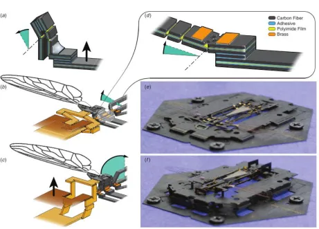
In 2012, a flying micro robotic insect (Mobee) was constructed using PCMEMS [25]. Mobee
featured many high DOF joints and piezoelectric actuators. To achieve the necessary lift-to-weight
ratio, Mobee used a variety of materials including carbon fiber reinforced plastic (CFRP), titanium,
polyimide, and brass. The brass was used on the top layer of the device as a way to fix joints
in place—after folding the device into its final shape, adjacent brass pads were soldered together
to prevent any unwanted motion. Precision manufacturing and alignment allowed for component
features as small as 10µm, and a total weight of only 90 mg.
Figure 2.3: Self assembling PCMEMS hexagonal prism [1].
make folding the device easier and more precise—the folding is similar to “pop up” books, where a
single actuation can create many out of plane features. The scaffold connected to any mechanisms
that needed to fold out of plane, and was based on a Sarrus linkage to pull pieces vertically into
position. Using the standard PCMEMS techniques, start-to-finish manufacturing time was less
than 24 hours [25]. Additional work on the wing hinge designs revealed that a small increase in
hinge length can drastically improve the lifespan of the wing hinges [27]. Rounding the corners of
the structural materials surrounding the joints did not seem to improve lifespan though.
Mobee can also be used to compare PCMEMS to other layered manufacturing procedures. A
comparable design for a small flying insect that used a simple layered manufacturing technique—
not PCMEMS—is the Micromechanical Flying Insect (MFI) [29]. The MFI had a total of 26 joints,
including some assemblies allowing 2, 4, and 5 DOF to articulate the wings. Two piezoceramic
actuators in each wing generated lift. Composite materials were used for most of the structural
elements, and non-solid designs (honeycombs) on some beams provided a higher stiffness to weight
ratio than traditional beams. The first difference between the MFI and Mobee is that the MFI was
hand assembled, it did not “pop up” into shape. Secondly, layer alignment with dowel pins was
not used for the MFI—pieces were aligned and assembled manually under a microscope, adding
2.3 PCMEMS 14
Figure 2.4: Folding assembly of Mobee PCMEMS device. (a) A four bar linkage turns linear actuation into rotation, also showing solder locking a joint in place. (b) The wing during and after (c) assembly. (d) A castellated joint, showing multiple layers of the device. (e) Mobee before and after (f) assembly with the scaffold frame [25].
The MFI weighed 28 g, which is very heavy when compared to the 90 mg of Mobee. These
differences illustrate that comparatively, PCMEMS allows for smaller and more precise components
with faster manufacturing than more basic layered manufacturing procedures.
Several PCMEMS medical devices have been developed, including other MIS graspers. The
first, by Gaffordet al. (Figure 2.5) was constructed from 11 separate layers of material with an 18
mm by 7.5 mm overall footprint [15]. The materials used were 50µm thick 304 stainless steel for
structural layers, 25 µm thick polyimide as a flexible layer, and DuPont FR1500 acrylic adhesive
to join the layers together. The grasper used three castellated hinges for articulation: one hinge on
each side of the body to support and guide the movement of the jaws, and one hinge in the middle
and it was determined that this hinge design could tolerate shear stresses of 26.8±0.53 N/mm2,
and torques of 22.8±2.15 Nmm per mm of hinge width before failure. Failure was predictable, and
it was found that the torsional strength of the hinges could be greatly improved by rounding the
corners of the steel in the castellated hinges to prevent tearing the polyimide.
Figure 2.5: PCMEMS minimally ivasive surgical grasper. Inset showing castellated hinges [15].
The grasper uses a serpentine spring as a passive restoring force, such that the jaws rest open
when no actuation load is applied. The jaws were were 1 mm wide and 10 mm in length, able to
lift objects up to 200 mg. Heavier weights could not be lifted due to a combination of a lack of
friction on the surface of the jaws, and compliance in the jaws themselves. It was noted by the
authors that adding out of plane features to the jaws could greatly improve stiffness.
Gafford created a second version of the grasper, adding the aforementioned stiffness
improve-ment, and adding an integrated strain gauge force sensor. The sensor was designed to measure
grasping forces up to 1.5 N in a single axis [16]. Unfortunately, a 1:1 scale prototype of this design
was not created, only a 2:1 model. The grasper was constructed from 15 individual layers of
mate-rial including stainless steel, polyimide, FR1500 acrylic adhesives, and constantan alloy (used for
the strain gauge material). The constantan alloy was added as the top layer of the laminate, with
the strain gauge pattern not appearing until after the device was laminated. A diode-pumped solid
state (DPSS) laser was used to ablate material from the constantan layer, forming the winding
shape of the strain gauges. A sensitivity of 408 mV/N was observed with the force sensor, and a
2.3 PCMEMS 16
Figure 2.6: Force sensing PCMEMS minimally invasive surgical grasper [16] c 2013 IEEE.
The jaw design was altered to include two out of plane folds, creating a triangular shape with
improved stiffness. The authors’ analysis show that jaw stiffness is increased by 200 times over the
original planar design. One more castellated hinge was added to each side of the jaws, to allow
the jaws to remain parallel to each other when opening and closing. The additional hinges also
increased the jaw strength. Although the grasper was designed to handle tip loads of only 1 N, the
additional hinges allowed for maximum tip loads of approximately 4 N. Importantly, it is noted
by the authors that the low cost of materials and labour make the device suitable for single-use,
eliminating the need for sterilization.
The most recent iteration of a PCMEMS grasper was manufactured to be suitable for
micro-surgery [11]. Although exact dimensions are not given, it appears that the grasper is approximately
5 mm wide. The triangular jaw structure of [16] was not used for this model—the grasper was
designed for relatively small forces, and therefore the increased stiffness may not have been
neces-sary. Similar to [16], a strain gauge with an on-board half-bridge was used to sense grasping forces.
added as layer during the construction of the device. Two simulated tasks—needle driving and
tissue retraction—were used as initial tests of the grasper, measuring forces up to 300 mN, with a
resolution of 5 mN. The grasper was then attached to a robotic micro-manipulation platform and
1 mm diameter steel balls were stacked into a pyramid using the grasper.
A microsurgical PCMEMS articulated arm was proposed, which used expanding bladders to
control movement [10]. The device was unique in that it was constructed primarily from soft
material, using various combinations of polydimethylsiloxane (PDMS) and Dragonskin 0020 to
create structural layers of varying stiffnesses that were soft and flexible. Microfluidic lines controlled
fluid flow into bladders. Depending on the desired function, bladders were attached to the other
layer of the device, and sandwiched between layers. A capacitive sensor was formed by adding a
layer of Pyralux (copper clad polyimide) patterned with capacitive electrodes to the each side of
the bladder. The sensor could then determine inflation position of the bladder. Three proposed
joint types using the expanding bladders are shown in Figure 2.7.
Figure 2.7: PCMEMS joints using expandable bladders. a) A linear actuator based on a Sarrus linkage. b) Bending mechanism with one side of the Sarrus linkage fixed. c) Bending mechanism with bladder mounted externally [10] c 2016 IEEE.
A flexible wrist designed to enhance endoscopic mobility was created with PCMEMS [13]. The
wrist is designed for single-use, and is made to fit on to the distal end of existing endoscopic
instrument shafts. 15 layers of material were used in the construction of the device including 75
µm 304 stainless steel for structural layers, 25µm polyimide for joints, 18 µm copper clad 25 µm
polyimide (Pyralux) for flexible printed circuits, and FR0100 acrylic sheet adhesive. The device
2.3 PCMEMS 18
scaffold. The jig uses push pins to actuate the pop-up mechanisms in the design, with Sarrus
linkages in the assembly frame to guide the structure, Figure 2.8.
Figure 2.8: Thumbscrew actuated jig for assembly scaffold of PCMEMS endoscopic wrist [13] c 2016 IEEE.
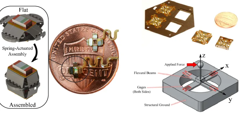
Two standalone PCMEMS force sensors were created by Gafford et al.. One of the sensors
measures forces in a single axis using light intensity modulation (LIM) [12], and one measures
forces in three axes using strain gauges in a cross configuration [14]. Both sensors use 50µm 304
stainless steel for structural layers, 25 µm polyimide for joints, copper clad 25µm polyimide for
flexible printed circuits, and FR1500 acrylic sheet adhesive, shown in Figure 2.9.
The sensor using LIM had a range of 200 mN and a resolution of 0.8 mN. With a footprint
of only 2.7 mm, the sensor was designed to fit through the working port of an 8.6 mm endoscope
for MIS. The structure of this sensor is very similar to that seen in the hexagonal prism created
in [1]. An emitter is mounted to one side of a hexagonal prism structure, across from it is the
detector. The sensor features an internal spring that is pre-tensioned before lamination. The
internal spring allows the sensor to self-assemble—when release cuts are made, the stored tension
in the spring pulls the sides of the sensor together, raising it into its working position. This spring
also provides the elastic element that couples the emitter to the detector. After assembly, the
sensor was encapsulated in a UV cured epoxy.
surgery, although a direct application is not stated. The sensor measures 1x1x2 cm, including the
signal conditioning circuitry. A strain gauge is located on both sides of each arm, for a total of 8
gauges. Similar to [11, 16] the strain gauges were formed by ablating constantan alloy. The strain
gauge beam width was 30 µm. The gauges were then connected to the remaining circuitry by
adding a layer of etched copper clad polyimide.
The sensor was made more rigid by folding and locking the outer flaps to form a box. These
folds used a combination of castellated and plastic hinges (a fold with serrations where the material
deforms plastically). The plastic hinges add some stiffness to the fold, making it more robust—this
is useful for joints that will be locked in place. To lock the box together, the same method as [25]
was used, with brass tabs soldered together. When tested, the device showed a range of -500 to
500 mN in the x and y directions, and -2.5 to 2.5 N in the z direction, with an RMS noise of 1.6
mN.
Figure 2.9: PCMEMS force sensors. (left) Self-assembling force sensor using light intensity modu-lation c2016 IEEE. (right) Three-axis force sensor using strain gauges c2014 IEEE.
Other devices using PCMEMS include a voice coil actuator that added pick-and-place
compo-nents both before and after lamination [28]. The device incorporated rigid and flexible circuitry,
with the circuitry added as a layer in the manufacturing process. A unique aspect of this design
2.4 Force Sensing Medical Instruments 20
process. The areas in the circuits that needed to be connected were tinned with solder, and reflow
soldering was used to form connections that flowed over intermediate layers in the device.
2.4
Force Sensing Medical Instruments
Many minimally invasive surgical instruments have been designed to incorporate force sensing.
Puangmaliet al. performed a review of existing technologies for force and tactile sensing in MIS
in 2008 [2], and Tiwana et al. provided a similar review in 2012 [30]. Sensor placement has
been discussed in Section 2.2.2, and though it has been decided to place the sensors at the tip of
instrument, it is useful to look a range of sensing technologies—including technologies that may
not be used at the tip of the instrument. The designed PCMEMS grasper should ideally function
at a level at least comparable to existing technologies. However, any technologies that cannot be
incorporated into the tool tip of the instrument were explored in less detail.
Puangmali et al. included examples of sensorized instruments that measured force using
dis-placement, resistance, capacitance, current, pressure, vibration, and optical sensors. These sensor
technologies were compared to determine which would be best suited for a high accuracy PCMEMS
device. Because the grasper is designed with the intention of being single-use, cost effective
tech-nologies were also given preference.
Some methods measure forces indirectly, such as a design by Tholey et al. that measured the
current applied to drive motors to determine applied torques or forces [31]. This method was not
very accurate though, because it failed to take into account secondary forces such as friction at
joints or linkages, and the inertia of all involved mechanism. A position based design by Rosenet
al. used a servo and encoder to measure position error, translated into a force feedback [32]. The
system was teleoperative, removing common error sources such as internal friction and backlash.
However, due to the relative complexity of systems such as these that use indirect sensing, these
methods are not well suited to a single-use MIS grasper designed using PCMEMS, and are not
considered further.
Optical sensors are a popular area of research for force sensing MIS instruments. Optical
interference [30]. Fiber Bragg grating systems, a type of fiber optic sensor, are common but often
feature very high cost signal conditioning and interrogation units to measure the signals. Attempts
have been made to lower the cost, such as the fiber Bragg grating systems designed by Yurkewich
et al. [33] and Tosi et al. [34]. Still, the optical fibers would need to be added as pick and place
components in a PCMEMS device, and need to run the length of the instrument. This makes
for a relatively more complex assembly process, and increases the cost of the needed components.
Using simple LED and photo-transistor pairs to measure LIM is better suited for PCMEMS. This
was seen in the endoscopic wrist module and self assembling force sensor developed by Gaffordet
al.[12, 13]. In order to measure forces in 3 DOF the system needs a minimum of three emitters,
three collectors, an elastic element, and constraint hinges. Fitting all of this through a 5 mm
trocar may be difficult.
The most common technology for force sensing in a MIS device is using strain gauges to
measure force through changes in resistance. Strain gauges require flexure of the object under
measurement, and there exists a trade-off between stiffness and sensor sensitivity—nonetheless,
strain gauges are generally considered accurate and low-cost. Many MIS instruments have been
designed using strain gauges. A relevant example is an instrument that placed strain gauges on
the shaft close to the end effector [6]. The strain gauges were placed in opposing pairs designed
to reduce noise. Accurate results were achieved, but only in two directions—forces along the shaft
were not able to be measured using this method.
Fischer et al. developed a 3 DOF force sensing grasper with strain gauges mounted to the
jaws [35]. The design used strain gauges in a full and half Wheatstone bridge, as well as a Poisson
bridge for a total of eight strain gauges. Parts of the instrument could be sterilized with an
autoclave, but others required ethylene oxide (EtO) sterilization. Trejoset al. worked on creating
an easily sterilizable force sensing grasper, comparing coatings and adhesives to determine which
would allow strain gauges to survive multiple autoclave cycles [36]. Their final prototype was able
to survive multiple autoclave cycles, with a 0.10–0.21 N accuracy, 0.05–0.20 N repeatability, and
hysteresis of 0.06–0.21 N, depending on the measurement direction. Strain gauges were mounted
on the instrument shaft near the grasper jaws, shown in Figure 2.10.
2.4 Force Sensing Medical Instruments 22
Figure 2.10: Sterilizable force sensing instrument. (top) Strain gauges installed on instrument inner shaft. (bottom) Sterilizable instrument with strain gauges mounted on shaft near end effector c 2014 IEEE.
Section 2.3.2. The PCMEMS surgical graspers that used strain gauges only measured forces in
one axis, with a relatively small sensing range [16]. Better results were achieved in the stand-alone
3 DOF PCMEMS force sensor (also using strain gauges) [14]. One of the previous drawbacks of
working with strain gauges was the time and precision required to install the often very fragile
strain gauges on to the instruments. PCMEMS alleviated this problem by adding a solid layer of
strain gauge material to the devices and using a laser to form the strain gauge pattern by ablating
material. It should be noted though that this method requires access to a precise laser, which may
not be possible with the available resources for this project.
Piezoelectric materials are often manufactured in very thin sheets or films, which may allow
them to be integrated easily in a PCMEMS design. Polyvinylidene fluoride (PVDF) is a
pop-ular piezoelectric material that can output large voltages under relatively small deformations.
Piezoelectricsproduce voltage, requiring no external electrical power to be supplied to the sensing
elements. Dargahiet al. used a PVDF film on the grasper jaws of a MIS instrument. The sensor
had a measurement range of 2 N, and excellent sensitivity was reported [37]. A PVDF sensor
element was designed by Sokhanvar et al. that could be usefully adapted to work with many
MIS tools [38], shown in Figure 2.11. The sensor consisted of a beam structure with two PVDF
films sandwiched under the end supports, and one under the flexible beam. The design allows the
sensors to function directly as a grasping surface. By measuring both the direct force applied, and
grasped. The sensor can be adapted for different force ranges by changing the Young’s Modulus
or dimensions of the flexible substrate.
Figure 2.11: PVDF sensor design. Flexible beam design with three sensor films can measure object hardness.
Teoet al. used a commercially available ’flexiforce’ sensor from Tekscan (a piezoresistive force
sensor) [39] to measure grasping force. The smallest commercially available flexiforce sensor, the
A101-1 (https://www.tekscan.com/products-solutions/force-sensors/a101) , is 7.6 mm wide. The
sensor would need to be modified to fit within a 5 mm instrument.
In both Puangmali [2] and Tiwana’s [30] review articles, the stated disadvantage of piezoelectric
materials is that they are not as suitable for measuring static forces. This is because piezoelectric
materials only measure changes in applied force, and are therefore subject to charge leakages under
static forces. Many piezoelectric films are also sensitive to changes in temperature, or can become
damaged at high temperatures. This is not ideal for a device that may need to be laminated at
200◦C.
Capacitive sensing is the final technique to be included for consideration. Puangmali notes
ca-pacitive sensing offers an advantage over strain gauges of excellent sensitivity without temperature
dependence [2], and Tiwana notes the additional advantages of a large dynamic range, and good
2.4 Force Sensing Medical Instruments 24
using capacitive sensing for force measurement have been designed.
Chang and Allen used MEMS processes to fabricate capacitive pressure sensors with read
out circuitry integrated directly into the sensor structure, by using lithography defined electrical
traces [40]. Although the finished structure was too large for use in a MIS instrument (5.7 x 5.7
cm), it demonstrated the concept of integrated sensors and circuitry. Gray and Fearing fabricated
a MEMS 8x8 array of capacitive sensor cells for tactile sensing that was less than 1 mm2[41]. The
sensor array could measure millinewton forces and could be used in grasping applications.
A capacitive shear force sensor developed by Chen et al. was manufactured based on PCB
techniques [42]. The prototype sensor consisted of a flexible dielectric layer (silicone rubber)
sand-wiched between two PCBs. Electrodes were directly patterned in the PCBs, forming a capacitive
pair across the silicone. The back side of the PCB was clad in copper to serve as a ground plane
and reduce electromagnetic interference. The silicone layer was added by injection molding, with
dielectric ceramic powder added to increase sensitivity (0.14 volume fraction). The sensor operated
on the principle of measuring differences in capacitance based on the shift and change in distance
between two bottom electrodes and a common top electrode, this is shown in Figure 2.12. The
sensor was tested to a maximum load of 10 N, with a resolution of 1 mN.
Figure 2.12: Capacitive shear sensor design principle. Shear force causes a translation and rotation of upper electrode. [42] c 2013 IEEE.
Capacitive sensors can integrate multiple axes of sensing in one unit. Multiple six-axis
force-torque capacitive sensors have recently been presented in literature. Brookhuiset al. developed a
MEMS fabricated six-axis sensor with a 9 x 9 mm footprint, capable of measuring 50 N of normal
combination of triangular electrodes to measure the normal force and moments in the x and y
di-rections, and a series of small overlapping “comb” electrodes to measure shear forces and moments
in the z direction. Micromachined silicone pillars form the spring element of the sensor.
Kim et al. manufactured a sensor based on a flexible cross with grooves holding capacitive
electrodes [44]. When a force deforms the cross, the distance between electrodes changes, providing
force data. The sensor measured forces up to 10 N, but had a relatively low resolution of 0.5 N.
Maximum measured torque was 0.16 Nm, with a resolution of 0.02 Nm.
Lee et al. created a sensor using a grounded top electrode disk, and three opposite electrodes
located in a circle 120◦ apart [45]. The sensor has an elastic structure supporting the grounded
disk, and an air gap between sensors, shown in Figure 2.13. The sensor electrodes are integrated
into a PCB with the capacitance to digital converter (CDC), similar to the sensor described by
Chenet al.[42]. Although the sensor is too large for a PCMEMS application, it demonstrated again
the use of PCB techniques by combining sensing electrodes into a PCB with read out circuitry
and a CDC.
Figure 2.13: Six-axis capacitive sensor by Leeet al. [45] c 2016 IEEE.
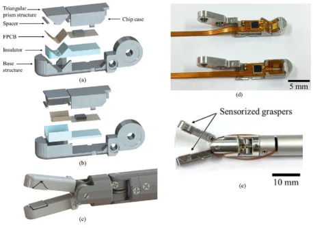
Two papers by Kim et al. document the development of a small grasper with four-axis
capaci-tive force sensing [46,47]. Both jaws on the grasper have a grounded electrode in a triangular prism
shape separated from a pair of angled electrodes by a layer of polydimethylsiloxane (PDMS). The
2.4 Force Sensing Medical Instruments 26
force sensing is shown in Figure 2.14. Electrodes in the top jaw are rotated 90◦ from those in the
bottom jaw, allowing the two jaws to resolve shear forces in separate axes.
Figure 2.14: Principles of operation of capacitive force sensing grasper. (left) Triangular prism structures under normal and shear forces. (right) Force measurements using both jaws [47] c 2015 IEEE.
The electrodes are patterned on a FPCB that also holds the CDC. Minimizing the distance
between the CDC and electrodes, and housing the CDC within the grasper jaws minimizes noise
and stray capacitance. The case and base structure of the grasper jaws are also grounded to block
out stray capacitance. A plastic insulator layer between the FPCB and base prevents shorting the
circuit. Construction of the device is shown in Figure 2.15.
2.4.1 Force Sensing Summary
Although there are other force sensing technologies that may be used for MIS instruments, it is
be-lieved that optical sensors, piezoelectric films, strain gauges, and capacitive sensing are best suited
for PCMEMS manufacturing. A summary of the force sensing technologies and their suitability
for PCMEMS is shown in Table 2.2.
Comparing each sensing technology, it is likely that all will be able to meet the required sensing
range. The remaining considerations are: accuracy, resolution, dynamic response, repeatability,
size, circuit simplicity, PCMEMS manufacturability, and temperature sensitivity. However, the
initial focus must be on ensuring the chosen sensor system is suitable for PCMEMS manufacturing,
Fiber optics have not been previously used with PCMEMS, and aren’t well suited for planar
manufacturing. LIM sensors, if used similarly to those in existing PCMEMS devices [12] may
require multiple emitters and detectors when measuring three axes of force, resulting in a bulky
and complex system. Similarly, including three-axis force sensing with strain gauges and signal
conditioning may prove too difficult to fit within such a small device—the previously demonstrated
PCMEMS three-axis strain gauge force sensor was over two-times too long and wide for an MIS
grasper application [14]. With piezoelectric films, no commercial solution exists that is small
enough for this project, and the temperatures required by the lamination process may result in
damage.
Capacitive sensors have been previously manufactured integrated into PCBs, including the
read out circuitry and a CDC chip—a method that should translate well to PCMEMS designs.
Capacitive sensors on FPCBs have successfully been integrated into a surgical grasper, showing
that at the scale needed, reliable sensing was still achieved. An advantage over strain gauges
was seen when incorporating multiple axes of force sensing—capacitive sensors were demonstrated
to be compact, and one unit could be simplified by having a common ground electrode used for
measuring multiple forces [42, 45–47]. Based on these advantages, capacitive sensors were chosen
2.4 Force Sensing Medical Instruments 28
T ec hnology Adv an tages Limitations PCMEMS Considerations Relev an t Examples
Optical sensors (LED
and Photo-dio de) LED and p hoto transistor pairings are simple and relativ ely small. Sensor information is d igital and can b e transmit relativ ely far. Can b e se n sit iv e to other ligh t sou rce s. Multiple DOF can quic kly increase complexit y of system. Has b een u sed successfully in PCMEMS designs as pic k and place comp onen ts. [33, 34]
Optical sensors (FBG)
2.5 Capacitive Force Sensing Principles 30
2.5
Capacitive Force Sensing Principles
Many of the capacitive sensors that were looked at operate on the principle of two electrodes
coupled by an elastic force element. As a force or torque is applied, the elastic element is deformed,
changing the distance between the two electrodes and affecting a change in capacitance. In some
cases this was an elastic element sandwiched between the electrodes [42, 47], or an elastic element
that supported one of the electrodes [45]. The principle is the same though, and capacitance
between two parallel plates is calculated as
C=ε0εrA
t, (2.1)
whereε0 is the relative permittivity of air, εr is the relative permittivity of the dielectric material
used between the plates (which may be the elastic element),A is the area that overlaps between
electrodes, andt is the distance between the plates. Applying a normal force compresses the elastic
element, changingt, and therefore changing the capacitance value. The change int can be simply
calculated using Hooke’s Law as
∆t= F t
EA, (2.2)
where∆tis the change in thickness,E is the modulus of elasticity for the elastic element, andF is
the applied force. (1) and (2) can be combined to determine the relationship between capacitance
and applied force, with the change in capacitance expressed as
∆C =ε0εr A t 1− F
AE
. (2.3)
This equation works for a simple elastic element under a normal force. If the element is under shear
however, a different set of equations must be considered. If the shear force moves the electrodes
out of alignment, the effective overlapping area is reduced, reducing capacitance. This effect can
be used to sense shear forces as done by Leeet al. [45], or can be mitigated by oversizing one of
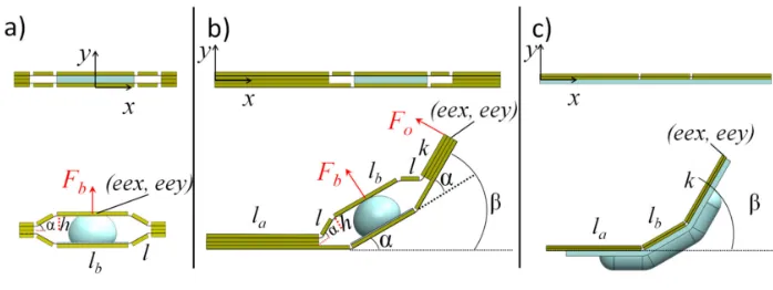
the electrodes, as by Kim et al. [47]. This effect is shown in shown in Figure 2.16. If the two
Figure 2.16: Capacitance changes under applied shear forces.(a) Capacitive sensor under normal force. (b) Capacitive sensor under shear, overlapping area A is decreased. (c) By increasing the size of the top electrode, overlapping area remains unchanged under shear forces [47].
the change in capacitance is simply related to the change in overlapping area, calculated as
∆C =C1−C2
=ε0εrA t −ε0εr
(A−δA)
t
= ε0εr
t (−δA)
= ε0εr
t (−Lxs).
(2.4)
Where δA is the area that one electrode is displaced, which can be represented by the width of
the electrode L multiplied by the linear displacement of the electrode xs. Assuming the elastic
element behaves linearly, Hooke’s law for shear stress can be employed. First the shear modulus
is calculated,
G= E
2.5 Capacitive Force Sensing Principles 32
where G is the shear modulus, and ν is the Poisson’s ratio of the material. Shear modulus is a
material property that can be used to calculate shear strain,
G= E 2(1 +ν)
γ = τ
G
γ = 2(1 +ν)
E τ,
(2.6)
whereγ is shear strain, expressed as the angle (in radians) caused by the shear stress, andτ is the
applied shear force. γ is simply
γ = xs
t , (2.7)
Combining shear and normal forces, it is important to note that a compression due to normal
force will change the effective thickness of the elastic element under shear, thereby reducing the
distance t used in Equation 2.7.
Of course, this deals only with linear deformations, and simple calculations. If more complex
assessments of strain and deformation are required, using a finite element analysis would be the
Design and Realization of the First
Prototype
3.1
Introduction
Based on the literature reviewed in Chapter 2, it was decided to focus on the use of PCMEMS
manufacturing with capacitive force transducers to produce a sensorized minimally invasive
sur-gical grasper. This chapter will examine the first prototype, including the development of the
mechanical design from initial concept through its final shape, material selection, layer position,
and layer patterning. The design of the sensing system is discussed in terms of function, theoretical
measurements, and PCB design.
3.1.1 Manufacturing Notes
Before continuing with the discussion of the mechanical design, some specifics of the manufacturing
process should be noted to clarify certain design specifications and design choices.
All the PCMEMS devices that were discussed in Chapter 2 were manufactured using a laser
to cut and pattern the material layers. Unfortunately, a suitable laser was not available for use
at Western University, therefore a micro milling machine (MMM) was used in its place. Although
this was suitable for small-scale proof of concept and prototype creation, it should be noted that
this method is not ideal for large scale production. A laser can cut patterns much faster, more
![Figure 2.1: Forces acting on minimally invasive instruments [17].](https://thumb-us.123doks.com/thumbv2/123dok_us/1980464.1261673/21.612.100.542.130.412/figure-forces-acting-minimally-invasive-instruments.webp)
![Figure 2.2: Alignment process for small chain [1].](https://thumb-us.123doks.com/thumbv2/123dok_us/1980464.1261673/26.612.93.528.121.377/figure-alignment-process-for-small-chain.webp)
![Figure 2.5: PCMEMS minimally ivasive surgical grasper. Inset showing castellated hinges [15].](https://thumb-us.123doks.com/thumbv2/123dok_us/1980464.1261673/29.612.196.421.211.373/figure-pcmems-minimally-ivasive-surgical-grasper-showing-castellated.webp)
![Figure 2.6: Force sensing PCMEMS minimally invasive surgical grasper [16] c⃝ 2013 IEEE.](https://thumb-us.123doks.com/thumbv2/123dok_us/1980464.1261673/30.612.203.405.122.389/figure-force-sensing-pcmems-minimally-invasive-surgical-grasper.webp)
![Figure 2.8: Thumbscrew actuated jig for assembly scaffold of PCMEMS endoscopic wrist [13] c⃝2016 IEEE.](https://thumb-us.123doks.com/thumbv2/123dok_us/1980464.1261673/32.612.135.483.171.347/figure-thumbscrew-actuated-assembly-scaold-pcmems-endoscopic-wrist.webp)
![Figure 2.13: Six-axis capacitive sensor by Lee et al. [45] c⃝ 2016 IEEE.](https://thumb-us.123doks.com/thumbv2/123dok_us/1980464.1261673/39.612.199.416.429.594/figure-axis-capacitive-sensor-lee-et-al-ieee.webp)