Reconstruction of Objects Buried in Layered Media
Based on an Equivalent Current Source
Peng Zhang1, 2, *, Peng Fei1, 2, Xin Wen1, 2, and Feng Nian1, 2
Abstract—In this paper, a novel algorithm based on an equivalent current source is proposed to reconstruct objects buried in a multilayered medium. First, a radiating current source, one part of the equivalent current source, is obtained directly in closed-form from scattering data via the signal-subspace method. Secondly, a nonradiating current source, the other part of the equivalent current source, is represented with the linear superposition of vectors in the noise-subspace. Finally, the objects and equivalent current source are reconstructed efficiently by solving an optimization problem in a lower dimensional linear space with the conjugate gradient (CG) method. To test the new method, the effects of the frequency of incident wave, array aperture size, and SNR are studied in detail. Numerical results show that the proposed method has a high capacity to reconstruct objects buried in a multilayered medium.
1. INTRODUCTION
Two-dimensional reconstruction of objects of arbitrary shape embedded in a multilayered medium using electromagnetic (EM) waves is an important research area in subsurface sensing. In particular, such applications are common to geophysical exploration, environmental characterization, and subsurface sensing of landmines, through-wall-imaging, medical imaging and underground structures [1–6]. Electromagnetic inverse scattering for subsurface sensing is complicated and challenging in two-fold: one is that electromagnetic wave propagation is essentially three-dimensional wave phenomena and waves interact in a complex way with ground surface, subsurface layers, and objects; the other is that this class of inverse problems involve intensive computation and are nonlinear and ill-posed. In spite of these difficulties, there has been a wide variety of ways to solve the inverse scattering problems over the past two decades.
Traditionally, the existing tomography algorithms are highly efficient. Generally, the principle of diffraction tomography is based on a linear relation between the spatial Fourier transform of the object and the scattered field for weak scatterers [7, 8]. However, when multiple scattering is important for strong scatterers, diffraction tomography becomes less accurate. To unravel multiple scattering effects, most nonlinear algorithms incorporate the nonlinear, multiple scattering effects into the inversion algorithm. The multiple scattering effects can be accounted for by posing the problem as an optimization problem whereby a forward scattering model is used to generate the scattered field data to match the experimentally measured data. Among many nonlinear inversion algorithms, the Born iterative method (BIM) [9], distorted Born iterative method (DBIM) [10] and contrast source inversion (CSI) method [11, 12] are three typical techniques to solve the well-known nonlinear and ill-posed inverse problem, while the most ambitious algorithm is the contrast source inversion (CSI) method. The CSI method has been used extensively for experimental medical, microwave, and geophysics
Received 18 August 2015, Accepted 9 November 2015, Scheduled 20 November 2015
* Corresponding author: Peng Zhang ([email protected]).
1 Beijing Institute of Radio Metrology and Measurement, China. 2Science and Technology on Metrology and Calibration Laboratory,
problems because it is computationally faster, has less memory as well as data requirements and easily accommodates a priori information. The basic idea of the CSI method is to construct an objective function that consists of data equation and object equation and then to minimize the objective function by alternatively updating the contrast and contrast source using the conjugate-gradient (CG) method. Recently, inspired by the subspace-based method and CSI method, Chen has proposed a subspace-based optimization method (SOM) to solve the inverse scattering problem in free space [13, 14]. The essence of the SOM is to obtain the deterministic part of the equivalent current source directly by calculating the singular value decomposition, (SVD) of the current-to-field mapping operator whereas to determine the rest part (the ambiguous part) by optimization. It has been proved that these features significantly speed up the convergence and make the algorithm perform robustly in the presence of noise.
However, to our best knowledge, the reconstruction of objects buried in a multilayered medium using the SOM has not been reported previously, and it is the main contribution of this work. In this paper, the subspace-based optimization method is used to deal with the inverse problem built in a multilayered medium. The objects are reconstructed by solving an optimization problem with the CG method. And the effects of the frequency of incident wave, array aperture size, and SNR are analyzed in numerical studies. The organization of the remainder of this paper is as follows. In Section 2, formulas for the SOM in a multilayered medium are derived. Several numerical examples of targets buried in a five-layer medium background are presented in Section 3. Finally, some conclusions are drawn in Section 4.
2. INVERSION ALGORITHM
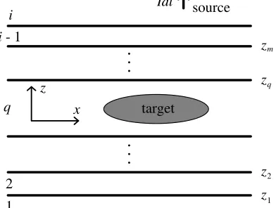
Consider a 2-D inhomogeneous object completely embedded in layerqof a planarly multilayered medium with layer interfaces parallel to the x axis. The geometry of the electromagnetic scattering problem is depicted in Fig. 1. The electrical properties of layer q and the object are characterized by the complex permittivity εq and ε, respectively. Here, we confine the problem to 2-D transverse magnetic (TM) inverse scattering case for simplicity, and the magnetic permeability μ is the same as that in layer q(μ=μq). Therefore, there are no induced magnetic sources in the object.
Suppose that domain Dis successively illuminated by a total number of Ni incident electric fields Eiinc, and the corresponding scattered fieldsEisca are measured on surfaceS in layer qoutsideD. Then following [11], the inverse problem can be described by the data equation
Eisca(r) =GSwi, r∈S, i= 1,2, . . . Ni (1)
and the object equation
wi =χEiinc(r) +χGDwi, r∈D, i= 1,2, . . . Ni (2)
wherewi(r) =χ(r)Eitot(r) is the equivalent current source andχ(r) =ε/εq−1 the contrast function.
.
.
.
.
.
.
target source Idl z x q 2 1 z z z z 2 1 m q i i - 1In the above, the linear integral operatorsGS,D are given by
GS,Dw(r) =kq2
D
Gmq(r,r)w(r)dr, r∈S or r∈D (3)
where the squared wavenumber k2
q = 2μqεq and Gmq(r,r) is a scalar Green’s function in a layered
medium mdue to a line source at r= (x, y) in the layered medium q, satisfying
μm∇ ·μ−m1∇+km2Gmq
r,r
=−δ
r,r
(4)
With the method of moments, Eqs. (1) and (2) can be discretized into the following two compact forms
esca = GS·w (5)
w = χ·einc+GD ·w (6)
Given the measured data on S and incident fields in D, one can obtain a contrast distribution representing the electrical properties of the object by solving the above nonlinear and ill-posed inverse scattering problem in a multilayered medium background. In the following, the SOM is briefly introduced. For more details, the reader is referred to [13].
Mathematically, the SVD of scattering operatorGS is given by the following equation
GS =
m
σmumv∗m (7)
where (ui, σi,vi) is the singular system of scattering operator GS, and the singular values with a total
number ofLnonvanishing ones are placed in nonincreasing order such asσ1≥σ2≥. . .≥σL≥σL+1 = . . . σM = 0.
From the basic property of SVD, the singular vectorsviform the complete set for the object domain of the scattering operator, and the equivalent current source can be represented as
w=
M
j=1
ajvj (8)
whereaj is the parameter to determine the equivalent current source.
By substituting Eqs. (7) and (8) into Eq. (5) and with simple deduction, one can get
L
j=1
ajσjuj =esca (9)
Then by multiply Eq. (9) withu∗j, one can find
aj = u
∗ j·esca
σj , j = 1,2, . . . , L (10)
From Eqs. (8) and (10), one has
w=
L
j=1
u∗j ·esca
σj vj+V
Nonrad·a (11)
whereVNonrad= [vL+1, . . . ,vM], a= [aL+1, . . . , aM]. Define
wRad =
L
j=1
u∗j ·esca
σj vj (12)
then Eq. (11) is formulated as
w=wRad+wNonRad (14)
where, wRad and wNonRad are called the radiating current and nonradiating current, respectively. From the above derivation, it is found that the radiating current can be directly obtained with Eq. (12), and the nonradiating current can be determined by solving the only unknown parametera.
In order to solve the unknown parametera, one can construct a cost function as follows
Δ = Δstate/esca2+ Δdata/wRad2 (15) The residue due to the mismatch between the calculated scattered field and the measured scattered field can be represented as
Δdata=GS·VNonrad·a+GS·wRad−esca2 (16) The residue due to the mismatch between the calculated and measured equivalent current sources can be formulated as
Δstate=A·a−b2 (17)
whereA=VNonrad−χ·(GD·VNonrad),b=χ·(einc+GD·wRad)−wRad.
After we add the residues for each incidence wave together, the cost function is given as
f(a1,a2, . . . ,aNi;χ) =
Ni
p=1
GS·VNonrad·ap+GS·wRadp −escap 2
escap 2 +
A·ap−bp2 wRad
p 2
(18)
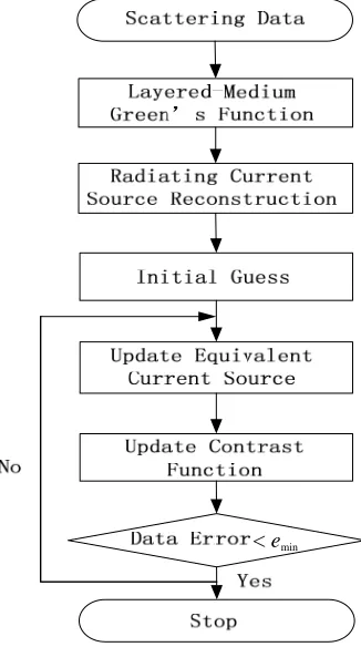
Then one can obtain the target profile through minimizing the cost function by alternatively updating the contrast and equivalent current source using the conjugate-gradient method. The flowchart of the computer program is shown in Fig. 2. Below we apply this imaging method to reconstruct 2-D objects in a layered medium.
< emin
3. NUMERICAL RESULTS
In this section, we have performed several numerical examples to validate the proposed inversion techniques in a layered medium. The configuration of a five-layer medium and a buried target is shown in Fig. 3. The dielectric constant and conductivity of the five layers studied here are (εr, σ) = (1.0, 0.0 S/m), (4.0, 0.0 S/m), (1.0, 0.0 S/m), (4.0, 0.0 S/m) and (1.0, 0.0 S/m), respectively. The second and fourth layers have the same thickness d= 0.2 m. The imaging domainD is a 2 m×2 m square region and is subdivided into 40×40 cells. In our simulation, the targets consist of four characters P, I, E, R, and their dielectric constant isεr= 2.
To facilitate the imaging setup in this work, we use two-sided arrays placed on the first and fifth layers. A linear array of length L= 6 m has 31 equally spaced transmitter/receivers with an interval of 0.2 m. All the synthetic data are generated using the volume electrical field integral equation technique known as the stabilized bi-conjugate gradient fast Fourier transform (BCGS-FFT) [15, 16]. A five-layer medium background Green’s function is calculated with the method provided in [17]. Fig. 4 gives the Green’s function G53 calculated with different methods for the configuration shown in Fig. 3. In the
z
z 2
1 z
z 4
3
target
z
x D L
d
2 m
2 m
d
L
Layer 5 (μ 0, ε )
r
Layer 4 (μ , ε )
Layer 2 (μ , ε )
Layer 1 (μ , ε )
0
0
Layer 3 (μ 0, ε 0)
0
0 0
r
Figure 3. Configuration of a five-layer medium background and a buried target.
following, numerical results are presented to study the effects of the frequency of incident wave, array aperture size, and SNR.
3.1. Effect of the Frequency of Incident Wave on Reconstruction
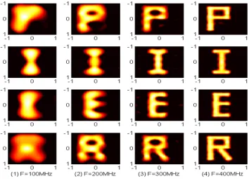
In this section, the effect of the frequency of incident wave on reconstruction is studied. A frequency marching approach which uses the inverted result at low frequency as the initial solution for the next frequency is carried out [18]. Fig. 5 shows the reconstructed results with the frequency marching method from 100 to 400 MHz. The relative MSE (Mean Squared Error) of the reconstruction is shown in Fig. 6. It is observed from these results that the quality of imaging is dramatically improved from low frequency to high frequency. Eventually, the targets are well recovered in terms of shape and location at the high frequency of 400 MHz. This is because more details of targets are obtained from the scattered field at high frequency when using the frequency marching method.
Figure 5. Reconstructed results using the frequency marching method at (1) 100 MHz, (2) 200 MHz, (3) 300 MHz, (4) 400 MHz.
3.2. Effect of Array Aperture Size on Reconstruction
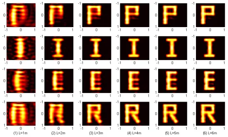
With the frequency marching approach improvement on the image reconstruction, we further consider the effect of array aperture size on the reconstruction. Fig. 7 shows the image reconstructions with the linear array aperture size of Lfrom 1 m to 6 m. The reconstruction is implemented at the frequency of 400 MHz by means of frequency marching approach. It is observed that the resolution of the images is gradually improved from narrow linear array aperture size of 1 m to wide linear array aperture size of 6 m, and the targets are well reconstructed in terms of shape and location. In Fig. 8, the MSE decreases fast from L = 1 m to L = 3 m while slowly from L = 4 m to L = 6 m. This is because the scattered field received by the array aperture with size smaller than that of the target does not contain enough angular spectrum information of the target, which is important for the reconstruction of high-resolution image. Thus, the array aperture size must be at least larger than the size of target in order to obtain high resolution reconstructed image.
Figure 7. Reconstructed results with a linear array aperture size of (1) L = 1 m, (2) L = 2 m, (3) L= 3 m, (4)L= 4 m, (5) L= 5 m, and (6) L= 6 m.
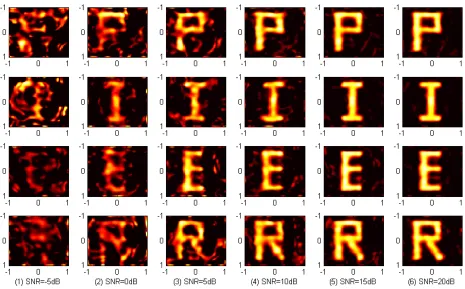
Figure 9. Reconstructed results using data ofL= 3 m Δx= 0.2 m under different SNR.
3.3. Effect of SNR on Reconstruction
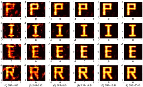
The results of the above examples have been obtained with noiseless data. In reality, it is important for the inversion method to be robust under noise contamination. In this section, the effect of SNR on the reconstruction results is discussed. The reconstructed images are evaluated under three different conditions: 1) L= 3 m Δx= 0.2 m; 2)L= 6 m Δx= 0.6 m; 3) L= 6 m Δx= 0.2 m and these images are presented in Fig. 9, Fig. 10 and Fig. 11, respectively. It is shown from the numerical calculations that the reconstructions are gradually improved with increasing SNR. Besides, the reconstructed images in Fig. 10 are deteriorated compared with the ones in Fig. 9 when the SNR is below 10 dB but improved
Figure 11. Reconstructed results using data ofL= 6 m Δx= 0.6 m under different SNR.
when the SNR is above 10 dB. This is in coincidence with the MSE of the three different conditions shown in Fig. 12. Generally speaking, wide array aperture size and small sampling interval are beneficial to obtaining well reconstructed images under noise contamination. However, small sampling interval and small array aperture size suit for the case of small SNR because the inversion is sensitive to sampling interval when the SNR is below 10 dB. On the contrary, wide sampling interval and wide array aperture size can improve the imaging result for the case of high SNR.
3.4. Discussion
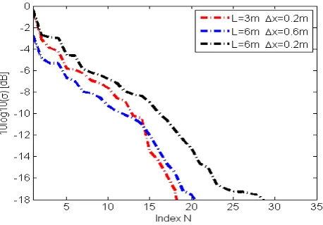
In this section, the effects of the frequency of incident wave, array aperture size, and SNR on the reconstructions are analyzed via the SVD of the scattering operator Gs. The SVD of the operator is mainly considered as a tool not only for obtaining a regularized solution to the ill-posedness inverse scattering problem, but also for analyzing the performance achievable in the reconstructions. The SVD of the operator, which connects the equivalent current source to the scattered field datum in Eq. (1), provides the singular system {un, σn, vn}∞n=0 [19]. The singular functions {un}∞n=0 and {vn}∞n=0 form the basis for the space of the visible objects and for the closure of the range of the operator respectively. The set {σn}∞n=0 denotes the sequence of the singular values ordered in a non-increasing sequence. In [13, 20, 21], it is demonstrated that the number of singular values above a chosen threshold corresponds to the number of singular functions in the inversion and thus determines the performance in the reconstructions. Namely, more singular functions achieve more stable solution of higher resolution. In the following, numerical SVD analysis is performed to investigate the effects of the frequency of incident wave, array aperture size, and SNR on the reconstructions. The behavior of the singular values above the threshold of 18 dB for these three cases is presented in Fig. 13, Fig. 14 and Fig. 15, respectively. In Fig. 13, the number of singular values above the threshold, called N for simplicity, increases from low frequency to high frequency. It means that the operator Gs for high frequency wave contains more singular functions and can provide higher quality of imaging, which has been verified in Fig. 5. Similarly, the conclusion can be drawn from Fig. 14, in which wider array aperture size has larger N. Larger N gives better performance in reconstructions, which has been testified in Fig. 7. Fig. 15 shows that the case of wide array aperture size and small sampling interval (L= 6 m Δx= 0.2 m) has the largestN and consequently provides the better reconstructions than other two cases. However, the case of small interval and small array aperture size (L= 3 m Δx = 0.2 m) has larger N than the case of wide interval and wide array aperture size (L= 6 m Δx= 0.6 m) when the threshold is above 10 dB but has smaller N when the threshold is below 10 dB. It suggests that small interval and small array aperture size performs better when SNR is low and inversely wide interval and wide array aperture size enhances the resolution for high SNR. This conclusion has also been supported by the results shown in Fig. 9–Fig. 12.
Figure 13. Singular values of the operator Gs for different frequencies of incident wave.
Figure 15. Singular values of the operator Gs for three pairs of array aperture size and sampling interval.
4. CONCLUSION
This paper proposes a 2-D equivalent current source inversion based imaging technique for layered media. The effects of the frequency of incident wave, array aperture size, and SNR on imaging were investigated and analyzed via SVD of the scattering operator. Numerical results demonstrate that object locations, shape, and their constitutive parameters can be reconstructed accurately through the use of multifrequency data with a suitable array aperture size and sampling interval even under noise background. Therefore, the proposed method can be used to solve inverse scattering problems in the field of through-wall-imaging, ground penetrating radar, etc. Future work includes the experimental verification of the inverse algorithm and the development of a 3-D extension of the proposed method.
ACKNOWLEDGMENT
This work was supported by the China Postdoctoral Science Foundation under Grant 2014M550782.
REFERENCES
1. Cui, T. J. and W. C. Chew, “Novel diffraction tomography algorithm for imaging two-dimensional targets buried under a lossy earth,” IEEE Transactions on Geoscience Remote Sensing, Vol. 38, No. 4, 2033–2041, Jul. 2000.
2. Meincke, P., “Linear GPR inversion for lossy soil and a planar air-soil interface,”IEEE Transactions on Geoscience Remote Sensing, Vol. 39, No. 12, 2713–2721, Dec. 2001.
3. Galdi, V., D. A. Castanon, and L. B. Felsen, “Multifrequency reconstruction of moderately rough interfaces via quasi-ray Gaussian beams,” IEEE Transactions on Geoscience and Sensing, Vol. 40, No. 2, 453–460, Feb. 2003.
4. Zhang, Z. Q. and Q. H. Liu, “3-D nonlinear image reconstruction for microwave biomedical imaging,”IEEE Transactions on Biomedical Engineering, Vol. 51, No. 3, 544–548, Mar. 2004. 5. Song, L. P., Q. H. Liu, F. Li, and Z. Q. Zhang, “Reconstruction of three-dimensional objects in
layered media: Numerical experiments,”IEEE Transactions on Antennas and Propagation, Vol. 53, No. 4, 1556–1561, Apr. 2005.
7. Cui, T. J. and W. C. Chew, “Diffraction tomographic algorithm for the detection of three-dimensional objects buried in a lossy half-space,”IEEE Transactions on Antennas and Propagation, Vol. 50, No. 1, 42–49, Jan. 2002.
8. Deming, R. and A. J. Devaney, “Diffraction tomography for multi-monostatic ground penetrating radar imaging,”Inverse Problems, Vol. 13, 29–45, 1997.
9. Wang, Y. M. and W. C. Chew, “An iterative solution of the two-dimensional electromagnetic inverse scattering problems,” Int. J. Imaging Syst. Tech., Vol. 1, No. 1, 100–108, 1989.
10. Chew, W. C. and Y. M. Wang, “Reconstruction of two-dimensional permittivity distribution using the distorted born iteration method,” IEEE Transactions on Medical Imaging, Vol. 9, No. 2, 218– 225, Jun. 1990.
11. Van den Berg, P. M. and R. E. Kleinman, “A contrast source inversion method,”Inverse Problems, Vol. 13, No. 6, 1607–1620, Jul. 1997.
12. Van den Berg, P. M., A. L. van Broehoven, and A. Abubakar, “Extended contrast source inversion,”
Inverse Problems, Vol. 15, No. 5, 1325–1344, Jun. 1999.
13. Chen, X., “Subspace-based optimization method for solving inverse-scattering problems,” IEEE Transactions on Geoscience and Remote Sensing, Vol. 48, No. 1, 42–49, Jan. 2010.
14. Chen, X., “Application of signal-subspace and optimization methods in reconstructing extended scatterers,” Journal of the Optical Society of America A, Vol. 26, No. 4, 1022–1026, Mar. 2009. 15. Xu, X. M. and Q. H. Liu, “The BCGS-FFT method for electromagnetic scattering from
inhomogeneous objects in a planarly layered-medium,” IEEE Antennas and Wireless Propagation Letters, Vol. 1, No. 1, 77–80, Feb. 2002.
16. Millard, X. and Q. H. Liu, “Fast volume integral equation solver for electromagnetic scattering from large inhomogeneous objects in planarly layered-media,”IEEE Transaction on Antennas and Propagation, Vol. 51, No. 9, 2393–2401, Sep. 2003.
17. Simsek, E., J. Liu, and Q. H. Liu, “A spectral integral method (SIM) for layered media,” IEEE Transactions on Antennas and Propagation, Vol. 54, No. 6, 1742–1749, Jun. 2006.
18. Chew, W. C. and J. H. Lin, “A frequency-hopping approach for microwave imaging of large inhomogeneous bodies,”IEEE Microwave Guided Wave Letter, Vol. 5, No. 12, 439–441, Dec. 1995. 19. Bertero, M. and P. Boccacci, Introduction to Inverse Problems in Imaging, Institute of Physics
Publishing, Bristol, U.K., 1998.
20. Persico, R., R. Bernini, and F. Soldovieri, “The role of the measurement configuration in inverse scattering from buried objects under the born approximation,” IEEE Transactions on Antennas and Propagation, Vol. 53, No. 6, Jun. 2005.
21. Soldovieri, F. and R. Solimene, “Through-wall imaging via a linear inverse scattering algorithm,”
![Figure 4. The Green’s function G53 calculated with the method in Ref. [16] and the FDTD method.](https://thumb-us.123doks.com/thumbv2/123dok_us/1987987.1262956/5.612.161.456.283.493/figure-green-function-calculated-method-ref-fdtd-method.webp)