Miniaturization of a PIFA Antenna for Biomedical Applications
Using Artificial Neural Networks
Asma Djellid1, 2, *, Lionel Pichon1, Stavros Koulouridis1, 3, and Farid Bouttout4
Abstract—This work deals with the optimization of an inverted F dual-band implantable antenna operating in Medical Device Radiocommunications Service (MedRadio, 401–406 MHz) and Industrial Scientific Medical (ISM, 902–928 MHz) applications bands. Artificial neural networks (ANNs) are implemented to minimize the size of the initial design. The ANN’s output with the physical and dielectric parameters of antenna as inputs is tested using COMSOL Multiphysics. The obtained results regarding the return loss S11, resonant frequency and bandwidth of the antenna are presented and discussed. Indeed, the size of the antenna is reduced by 21.48% with respect to the initial size while preserving its initial good performance in both frequency bands.
1. INTRODUCTION
Implantable medical devices (IMDs) have become more and more interesting for healthcare services since the introduction of the implantable pacemakers in the early 1960s. Medical applications include, among others, glucose monitoring and insulin pumps.
Antennas play a major role in implantable systems because they assure the wireless link between the implant and external equipment [1, 2]. As an example, a small size dual-band implantable antenna, operating in Medical Implant Communications Service (MICS) and ISM bands, has been described in [3]. Li et al. designed the wireless link of a novel vascular stent antenna [4]. In [5], Bakogianni and Koulouridis proposed an implantable planar dipole antenna for operation in the MedRadio.
Due to their simple structure, many research groups have widely used planar inverted-F antennas (PIFAs) for implantable devices. For example, in [6], two antennas are proposed for an implantable medical device based on a PIFA configuration. In [7] a prototype of a complete PIFA antenna system including power supply and data communication, designed for an implanted glucose sensor, has been presented. A compact PIFA with bandwidth enhancement technique is proposed in [8] for implantable biotelemetry in MICS band. In [9] a miniaturized PIFA is proposed for the 2.4 GHz ISM band has been proposed.
To optimize the performances of a design using conventional optimization algorithms integrated in simulation software, a first design is created and submitted to simulation. Then the optimization method makes changes, and new simulations are performed iteratively until the desired criteria are met. In antenna design such an approach requires a significant computational running time. ANNs are able to predict the parameters of the antenna without using heavy modeling techniques. The ANNs reduce the optimization running time and directly provide the parameters of the antenna corresponding to the desired performances.
Received 27 March 2018, Accepted 28 May 2018, Scheduled 21 June 2018 * Corresponding author: Asma Djellid ([email protected]).
To tune and improve the antenna characteristics, ANNs method have been used in several papers. Using ANNs, a comparative study of neural network training is applied to adaptive beam forming of antenna arrays [10]. ANNs are proposed in [11] for the design of aperture-coupled microstrip antennas. In [12], ANN is developed for 2D Direction of Arrival (DOA) estimation using rectangular antenna array geometry. ANNs are presented in [13] for predicting the slot-size on the radiating patch and inserted air-gap to improve the performance of rectangular microstrip antennas. An ANN technique has been used in [14] to analyze and design a circular fractal antenna and to optimize a dual ring antenna [15]. In [16], authors have concluded that ANN gives better results than the Fuzzy method in the calculation of the performance of a coplanar strip line. Among the different training methods, the Levenberg-Marquardt (LM) backpropagation algorithm has been demonstrated to be the most efficient [17].
In this paper, the starting geometry considered is a PIFA structure presented in [18] but modified for the goal of dual-band operation and size miniaturization. The paper is organized as follows. In Section 2, the design procedure of the dual-band operation of antenna is outlined and illustrated by a practical antenna loaded by a biomedical tissue. Section 3 is devoted to miniaturization of size of the antenna following an optimization algorithm based on ANNs and training LM backpropagation method while maintaining the dual-band operation. The initial design and the ANN optimized antenna are compared, and their performances in terms of reflection levels, far field radiation patterns, and electric surface current on the conductor at the required frequency bands are reported and commented. A significant size miniaturization of the final optimized design with respect to the initial design is obtained. Section 3 is a conclusion where the type of antennas, the methodology used and the main findings of the study are summarized.
2. PIFA DESIGN AND RESULTS
The steps of the design procedure of the PIFA under study are summarized as follows:
Step #1: Start from a raw structure of PIFA fed with a microstripline with a short pin of cubic form located at the front-end of substrate.
Step #2: Compute the resonance frequencies of the antenna using an electromagnetic software; typically COMSOL Multiphysics.
Step #3:
if the resonance frequencies cover the MedRadio and ISM frequency bands, then done and exit. else, modify the dimensions of the slots and the positions of the short pin and the excitation port using an optimization algorithm under Matlab.
endif
Step #4: repeat from Step #2.
To illustrate the feasibility of the procedure above, a practical design is detailed as follows. The original antenna in [18] covers two frequency bands, MedRadio (401–406 MHz) for telemetry and
(a) (b)
915 MHz for wireless power transmission. It is firstly altered by replacing the coaxial feeding by a transmission line excitation. Then the shorting pin is modified from cylindrical to rectangular form, and it is moved to the extreme of the substrate in order to avoid the use of holes in the substrate that can affect the antenna performance. Also the realization is easier. Finally the dimensions of slots, position of the shorting pin in (zaxis) and the position of the port of excitation in (xaxis) are modified in order to have the same performances of the original design.
The geometrical configuration of the modified slot PIFA antenna is shown in Fig. 1(a). The antenna consists of a ground plane of 16×14 mm2surface area printed on the lower side of a substrate of thickness 0.635 mm, relative permittivity of r = 10.2 and tanδ = 0.003. On the upper side of substrate, the radiation patch is etched. It has a surface of 15.8 ×13.8 mm2 and contains the irregular slot with dimensions illustrated in Table 1. We introduce two slots S4 and S5 for the transmission line feeding technique at xport = −5 mm. The shorting pin is moved at the edge (as compared to [18]) and is formed in a bloc structure that has a volume of 0.1×0.635×0.3 mm3 atzpin=−3.5 mm. An identical superstrate covers the radiation surface. As illustrated in Fig. 1(b), the PIFA antenna is placed inside
Table 1. Dimensions of slots of the PIFA antenna. All values are in mm.
l1= 10.2 l2= 12.9 l3 = 1.9
w1 = 0.9 w2 = 1.3 w3 = 0.8
Table 2. Properties of the tissue layers.
402 MHz 915 MHz
r σ r σ
Skin 46.741 0.6889 41.329 0.8716 Muscle 57.112 0.7960 54.997 0.9480 Bone 13.143 0.0910 12.440 0.1450
(a) (b)
the cylindrical armtissue model at depthd= 10 mm. The armtissue model consists of three layers: skin, muscle, and bone with thicknesses 2.5, 25, and 22.5 mm, respectively. The properties of the 3 layers of tissue are given in Table 2 [18].
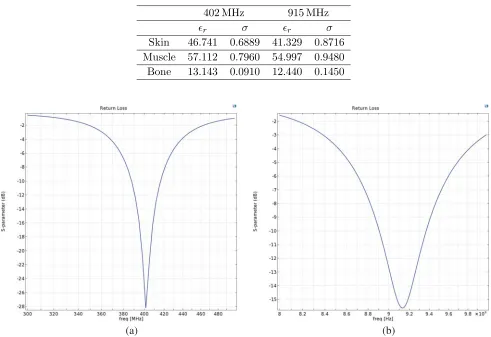
The simulation results of the antenna using COMSOL Multiphysics are shown in Figs. 2(a) and (b). Fig. 2(a) illustrates the simulated S11 of the implantable PIFA into the muscle tissue in dB. The resonance frequency is 401.65 MHz for MedRadio band with impedance matching (S11=−28 dB), and it presents a bandwidth of 30 MHz (388 to 418 MHz), fully covering the MedRadio band. In Fig. 2(b),
S11 parameter of the second resonance of the antenna, corresponding to the frequency 914.5 MHz, is shown. As seen the −10 dB impedance bandwidth is 48 MHz (890 to 938 MHz) which covers the ISM band.
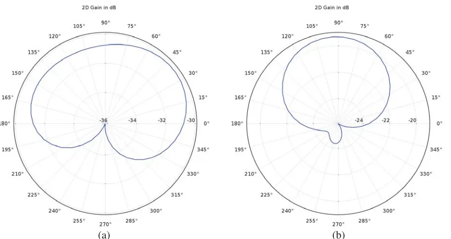
The 2D far field gain in dB in (xy) plane of the proposed PIFA antenna when implanted in the muscle tissue is presented in Figs. 3(a) and (b) for MedRadio and ISM bands, respectively. Despite the small PIFA size, the antenna radiates in both frequencies nearly omnidirectional with maximum values of −31.6 dB (−35.6 dB in [18]) for MedRadio band and−21 dB (−23.4 dB in [18]) for the ISM band.
(a) (b)
Figure 3. Two dimensional gain pattern of the PIFA at (a) 402 MHz, (b) 915 MHz.
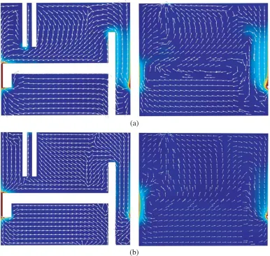
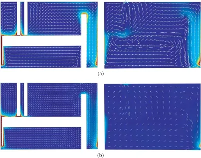
The detailed current distributions on the patch and ground plane of the PIFA antenna are also presented in Figs. 4(a) and (b) for the two bands, MedRadio and ISM, respectively.
The maximum current amplitude on the patch surface occurs near the shorting pin and the third slot for the two resonant frequencies. It is seen that for both frequencies the current on the patch and the currents on the ground plane are anti-phase.
3. MINIATURIZATION USING NEURAL NETWORK TECHNIQUE
3.1. Artificial Neural Network
Artificial Neural Network (ANN) consists of layers. Each layer is a group of single units named artificial neurons. The artificial neurons of different layers are connected. Every connection entering a neuron has a weight assigned to it; the weighted sum of the inputs constitutes the activation of the neurons. The activation signal is passed through a transfer function to produce the output of a neuron [16].
(a)
(b)
Figure 4. Current distribution on patch and ground plane of the PIFA at (a) 402 MHz, (b) 915 MHz.
more hidden layers, then an output layer. The output of neuronj in the hidden layer is:
yj =f( n
i=1
aijxi) (1)
wherexi are input signals,aij their respective weights of connection with the neuron (j) of the hidden layer, and f is an activation function. It can be a simple threshold, sigmoid, or hyperbolic tangent function [19].
In our study, a sigmoid function is used as the activation function. The objective function to minimize is the sum of squared differences between the desired (yd) and actual values of the output neurons (y). It is defined as follows
sse= 1 2
j
(ydj−yj)2 (2)
To get the desired response, weights and biases for neurons are modified using different learning algorithms. The learning algorithm used in this study is LM algorithm since it provides a very strong performance as being the fastest and the most accurate algorithm in such high dimensional input problems [17]. Using the LM algorithm, the new weight vector ak+1 can be obtained from the previous weight vector ak as follows [16]:
whereJk is the Jacobian ofsse(ak) evaluated by taking the derivative ofsse(ak) with respect toak,λ the Marquardt parameter set to 0.01, and I the identity matrix [16, 20].
3.2. Application to the PIFA Antenna
In Fig. 5, the inputs of the networks are the two resonant frequencies in the two bands (MedRadio and ISM) of the antenna, and the outputs are the parameters. Three steps are necessaries in ANN.
Figure 5. Artificial neural network used to minimize the slot PIFA antenna.
3.2.1. The Data Samples
In our case, the data are combination of antenna’s parameters (width of the patch (W), size of slots (li, wi,i= 1,2,3), pin position (zpin) and position of feeding port (xport)). The resonance frequencies in MedRadio and ISM bands obtained via COMSOL Multiphysicsprovide the sample data of the ANN. The ranges of the training data sets are in Table 3.
Table 3. Ranges of training data. All values are in mm.
6≤l1 ≤10.5 10≤l2 ≤12.9 0.5≤l3≤3 0.1≤w1 ≤0.7 0.1≤w2 ≤3 0.2≤w3≤3 9.8≤W ≤13.8 −5≤zpin≤+5 −7 ≤xport ≤+4
3.2.2. Training
After several trials, the structural configuration of the model is optimized as 2-35-6 for the best performance. It means that there are 2 neurons in the input layer, 35 neurons in hidden layer, and 6 neurons in the output layer. The weights and biases are optimized using LM training algorithm, once the training has been completed, the network is able to interpolate results for different inputs.
3.2.3. Validation
The validation verifies that the neural network’s system after learning is able to predict the desired output for the values given at the input which are not used in the learning. The minimized antenna with parameters given by the ANN is illustrated in Fig. 6 (the antenna having the smallest W (width of the patch) is chosen).
Figure 6. Geometry of the optimized PIFA antenna.
Table 4. Parameters of optimized PIFA antenna. All values are in mm.
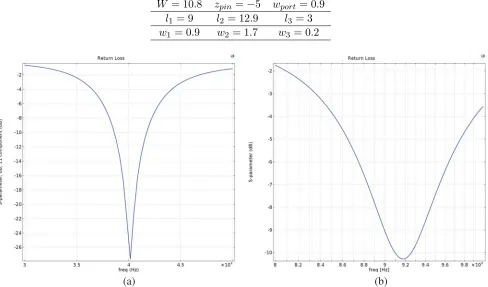
W = 10.8 zpin=−5 wport = 0.9
l1= 9 l2 = 12.9 l3 = 3
w1 = 0.9 w2= 1.7 w3 = 0.2
(a) (b)
Figure 7. Reflection coefficient of the optimized PIFA in (a) MedRadio, (b) ISM band.
(a) (b)
Figure 8. Two dimensional gain pattern of the optimized PIFA at (a) 402 MHz, (b) 915 MHz.
(a)
(b)
Figures 8(a) and (b) present the simulated 2D far field gain pattern of the optimized PIFA antenna implanted in the muscle tissue, and the gain attains maximum values of −31.6 dB and −21 dB in MedRadio and ISM bands, respectively.
The surface current distribution on the patch and ground plane of the optimized slot antenna in the two frequencies are presented in Figs. 9(a) and (b). The current distribution of the optimized antenna is similar to the original one. For both frequencies, the current on the patch is anti-phase with the current on the ground plane.
By comparing the performances of the initial PIFA antenna and the minimized one, it is clear that the minimized antenna has the same performances of the initial design. So by using the ANN, we have minimized the size of the PIFA by 21.48% antenna (from 16×14×1.72 mm3 to 16×11×1.72 mm3) of the initial one.
4. CONCLUSION
In this paper, an implanted compact PIFA has been designed and optimized for wireless data telemetry and power transmission operation taking into account the surrounding medium having the properties of biological tissues. Firstly, the proposed antenna has been designed to operate in the MedRadio and ISM frequency bands. Then, ANNs have been used to optimize the antenna by minimizing the total size and keeping the same resonant frequencies as the first design. A reduction of 21.48% from the initial size is obtained which is a significant improvement towards the goal of antenna miniaturization. The current study could help to design miniature planar antennas for multiband operation.
REFERENCES
1. Beach, R. D., F. V. Kuster, and F. Moussy, “Subminiature implantable potentiostat and modified commercial telemetry device for remote glucose monitoring,”IEEE Trans. Instrum. Meas., Vol. 48, No. 6, 1239–1245. Dec. 1999.
2. Beach, R. D., R. W. Conlan, M. C. Godwin, and F. Moussy, “Towards a miniature implantable in vivo telemetry monitoring system dynamically configurable as a potentiostat or galvanostat for two- and three-electrode biosensors,”IEEE Trans. Instrum. Meas., Vol. 54, No. 1, 61–72, Feb. 2005. 3. Karacolak, R. Cooper, and E. Topsakal, “Electrical properties of rat skin and design of implantable antennas for medical wireless telemetry,”IEEE Transactions on Antennas and Propagation, Vol. 57, No. 9, 2806–2812, Sep. 2009.
4. Li, C., P. Zhao, J. Du, C. Jiang, and Y. Ren, “Wireless link analysis of cardiovascular stent as antenna for biotelemetry,” IEEE Global Conference on Signal and Information Processing (GlobalSIP), Orlando, FL, USA, Dec. 14–16, 2015.
5. Bakogianni, S. and S. Koulouridis, “An implantable planar dipole antenna for wireless medradio-band biotelemetry devices,” IEEE Antennas and Wireless Propagation Letters, Vol. 15, 234–237, Jun. 2015.
6. Kim, J. and Y. Rahmat Samii, “Planar inverted-F antennas on implantable medical devices: Meandered type versus spiral type,” Microwave and Optical Technology Letters, Vol. 48, No. 3, 567–572, Mar. 2006.
7. Merli, F., L. Bolomey, E. Meurville, and A. K. Skrivervik, “Implanted antenna for biomedical applications,” Antennas and Propagation Society International Symposium, San Diego, CA, USA, Jul. 2008.
8. Lee, C. M., T. C. Yo, F. J. Huang, and C. H. Luo, “Bandwidth enhancement of planar inverted F antenna for implantable biotelemetry,” Microwave and Optical Technology Letters, Vol. 51, No. 3, 749–752, Mar. 2009.
10. Zaharis, Z. D., K. A. Gotsis, and J. N. Sahalos, “Comparative study of neural network training applied to adaptive beamforming of antenna arrays,” Progress In Electromagnetics Research, Vol. 126, 269–283, Mar. 2012.
11. Bose, T. and N. Gupta, “Design of an aperture-coupled microstrip antenna using a hybrid neural network,” IET Microwaves, Antennas and Propagation, Vol. 6, No. 4, 470–474, Mar. 2012.
12. Agatonovi, M., Z. Stankovi, I. Milovanovi, N. Doncov, L. Sit, T. Zwick, and B. Milovanovi, “Efficient neural network approach for 2D DOA estimation based on antenna array measurements,”
Progress In Electromagnetics Research, Vol. 137, 741–758, 2013.
13. Khan, T., A. De, and M. Uddin, “Prediction of slot-size and inserted air-gap for improving the performance of rectangular microstrip antennas using artificial neural networks,” IEEE Antennas and Wireless Propagation Letters, Vol. 12, 1367–1371, Oct. 2013.
14. Sivia, J. S., A. P. S. Pharwaha, and T. S. Kamal, “Analysis and design of circular fractal antenna using artificial neural networks,” Progress In Electromagnetics Research, Vol. 56, 251– 267, Nov. 2013.
15. Manh, L. H., F. Grimaccia, M. Mussetta, and R. E. Zich, “Optimization of a dual ring antenna by means of artificial neural network,” Progress In Electromagnetics Research, Vol. 58, 59–69, Jan. 2014.
16. Aouiche, A., A. Djellid, and F. Bouttout, “Fuzzy neuroconformal analysis of multilayer elliptical cylindrical and asymmetrical coplanar striplines,”AEU — International Journal of Electronics and Communications, Vol. 69, No. 9, 1151–1166, Sept. 2015.
17. Neupane, N. and S. Shakya, “Comparative analysis of backpropagation algorithm variants for network intrusion detection,” International Conference on Computing, Communication and Automation (ICCCA), Greater Noida, India, May 5–6, 2017.
18. Bakogianni, S. and S. Koulouridis, “Design of a novel miniature implantable rectenna for in-body medical devices power support,” 10th European Conference on Antennas and Propagation (EuCAP), Davos, Switzeland, Apr. 10–15, 2016.
19. Christodoulou, C. and M. Georgiopoulos, Applications of Neural Networks in Electromagnetics, Artech House, Inc., Norwood, MA, USA, 2000.