Harmonic Transponders: Performance and Challenges
Kimmo Rasilainen*, Janne Ilvonen, Anu Lehtovuori, Jari-Matti Hannula, and Ville Viikari
Abstract—Performance of a harmonic transponder strongly depends on the properties of the antenna and diode used, which makes finding a good combination of them very important. For a transponder with a fixed antenna geometry, the effect of different diodes is analyzed through electromagnetic simulations and theoretical calculations. The antenna used in the transponder is directly matched to the impedance properties of a particular diode. Effects of both detector and varactor diodes on the return loss characteristics of the antenna and the obtainable transponder response are observed. Criteria for selecting a suitable diode are given. Benefits and drawbacks of using different antenna matching techniques are discussed, and principal design steps are given both for transponders matched directly to the antenna and for transponders with external matching circuits.
1. INTRODUCTION
Wireless sensors and sensing have become increasingly ubiquitous in recent years. Examples of different wireless sensor technologies include resonance sensors, surface acoustic wave (SAW) sensors and radio-frequency identification (RFID) tags [1]. In RFID, which is possibly the best-known wireless sensor technology for the general audience, the tag consists of an antenna and an RFID chip. A particular reader device is used to obtain the response of the tag. RFID-based sensing systems can also have significant potential in future Internet of Things (IoT) applications [2, 3].
Another concept technologically somewhat related to RFID is the so-called harmonic or secondary radar, which was first introduced in [4]. In this concept, a desired target is interrogated at a certain fundamental frequency f0, and the reflected transponder response at a harmonic (integer) multiple frequency nf0 is picked up at the receiver. In principle, any harmonic frequency could be used, but most practical implementations have been realized using the second harmonic frequency (2f0).
Harmonic radar and transponders have been applied to, e.g., insect tracking [5, 6] and locating avalanche victims [7]. Depending on the application and technology, the used fundamental frequency varies. In RECCO avalanche detectors [7], a fundamental frequency of 0.917 GHz is used, whereas other technologies [8, 9] operate using maritime radar frequencies (f0 ≈ 9.4 GHz) or at the ISM band (f0 being, e.g., 2.45, 5.8, or 5.9 GHz [10–12]). One particular challenge for practical, commercial harmonic transponder applications and their widespread use is finding a suitable frequency pair that complies with existing frequency allocations simultaneously at both frequencies.
In the harmonic radar tag (also called a transponder), a nonlinear element (such as a Schottky diode) is used to generate the harmonic frequency. Communication between the transponder and the transmitter/receiver (Tx/Rx) is handled by the antenna which is matched at the two desired, harmonically separated frequencies. Compared to dual-band RFID tags (see e.g., [13]), the requirement of harmonically spaced operating frequencies makes harmonic transponders considerably more challenging to design than conventional, single or dual-band RFID tags.
Received 16 January 2015, Accepted 17 February 2015, Scheduled 7 March 2015 * Corresponding author: Kimmo Rasilainen ([email protected]).
Recently, characterization, design, evaluation, and implementation of harmonic transponders have been presented, e.g., in [14–19]. Operation of a transponder consisting of an antenna and a Schottky diode is investigated both theoretically and experimentally in [18]. One possible antenna design strategy suitable for harmonic transponder applications is shown in [19]. However, determining an optimal antenna-diode combination resulting in the best possible transponder performance is not straightforward with this kind of design.
This paper investigates and compares the performance of harmonic transponders when different diodes are used with a fixed, predetermined antenna geometry. In order to obtain a strong harmonic response, i.e., received power at frequency 2f0, it is essential that the two operating (resonant) frequencies of the transponder are harmonically separated. With a fixed antenna geometry, adequate matching at harmonic frequencies might not be obtained with certain diodes, or the transponder might operate at unpredictable or unwanted frequencies. In light of these aspects, an alternative design procedure is proposed and discussed to overcome some of the possible challenges and to provide more flexibility to the transponder design.
2. THEORETICAL CHARACTERIZATION AND INVESTIGATED ANTENNA STRUCTURE
2.1. Equivalent Circuit Model
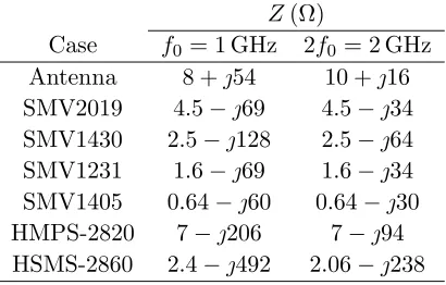
To determine the harmonic response that can theoretically be obtained, the transponder is represented using circuit models for the antenna and the diode as shown in Figure 1. In the equivalent circuit, the antenna is represented as a Th´evenin equivalent circuit whose impedance is expressed as Za = Ra+jXa =Rrad+Rloss+jXa, withRradand Rloss being the radiation and loss resistance, respectively, and Xa being the reactance.
Va
Rr Rl Xa
Za
Ls Rs
Cp
Cj0 Rj
Za
Zd
Ij,2ω0
Zj
Antenna
Diode
'
'
Figure 1. Equivalent circuit used to model the harmonic transponder. The antenna is represented as a Th´evenin equivalent circuit. Modified from [18].
The circuit model of the Schottky diode consists of a series inductance Ls, a parasitic capacitance Cp, a series resistance Rs, a small-signal junction resistance Rj, a small-signal junction capacitance Cj0, and a current source. Effects of the diode packaging are described by the Ls and Cp terms [20]. Subsequently, the junction impedance of the diode is abbreviated as Zj= (jωCj0+ 1/Rj)−1.
In typical operating conditions of the harmonic transponder, the excitation power is low. For this case, the equivalent circuit can be used to formulate an expression for the power generated by the transponder at the second harmonic frequency as [18]
where
F1 =
Zj,ω0 Rs,ω0 +Zj,ω0
4 Z d,ω0 Z
a,ω0 +Zd,ω0
4
F2 =
Z
j,2ω0 Rs,2ω0+Zj,2ω0
2 Z d,2ω0 Z
a,2ω0 +Zd,2ω0
2
F3 = ηω40Ra2,ω0η
2 2ω0R
2 a,2ω0
F4 =
ω0Cj0γ
2Φ −
jα 4Rj
2 .
Above, notations Za = Za +jωLs, (Zd)−1 = jωCp + (Rs +Zj)−1 have been used to simplify the expression. The terms F1 and F2 depend on the diode size and parasitics at f0 and 2f0, respectively. The radiation efficiencies of the antenna at f0 and 2f0 are included in F3. Term F4 contains zero-bias junction potential Cj0, junction potential Φ, profile parameterγ, andα =q/nkT (q is the elementary charge, k is the Boltzmann constant and T is a temperature). The value of F4 depends on the diode type (varactor or detector diode), and on the dominant type of non-linearity of the diode (capacitive or resistive, respectively). At the second harmonic frequency, the power due to the capacitive non-linearity is proportional to the square of the fundamental frequency, whereas the power due to the resistive non-linearity is frequency-independent.
As can be seen in expressions F1–F3, the impedance and efficiency terms at the fundamental frequency are squared compared to those at the second harmonic frequency. This indicates that having a good radiation efficiency and impedance matching at the fundamental frequency is more important, especially if they cannot be optimal simultaneously at both frequency bands.
2.2. Investigated Transponder Design
Figure 2 shows the transponder design [18] used to study the effect of different non-linear elements. The antenna is directly matched to the diode, which means that the desired frequency characteristics are obtained by modifying the antenna geometry. Impedance matching is realized at harmonically separated frequenciesf0and 2f0. In the example transponder implementation and in this work, targeted operating frequencies of f0 = 1 GHz and 2f0 = 2 GHz are selected. These frequencies are chosen solely for demonstration purposes, and are not intended to be compatible with any particular transponder systems or applications.
The impedance characteristics of the antenna have been designed to the impedance level of the SMV2019 Schottky varactor diode [see Section 3] using Rogers RT/duroid 5870 substrate (εr = 2.33). Figure 2 also illustrates the configuration in which the diode is connected to the antenna. In addition to the diode, which provides the necessary frequency multiplication, a 100-nH inductor is mounted parallel to the diode to achieve a proper DC bias. Different parts of the antenna contribute to creating desired resonant frequencies and to tuning the matching level. More details on the design principles and the effects of the different parts of the transponder antenna can be found in [18, 19].
3. TRANSPONDER PERFORMANCE WITH DIFFERENT DIODES
In the following, the transponder is investigated using different diodes to see how strongly they affect the performance and characteristics of the transponder. The varying impedance levels of different diodes may lead to impedance mismatch, which causes resonant frequency shift. For this reason, changes observed in both impedance matching and consequent effects on the harmonic response of the transponder are considered. The harmonic response with the different diodes is calculated according to (1).
10 17.2 1.5
0.2
63 35
80
29 5
0.2 1
14.7
Diode and inductor in parallel
Figure 2. Illustration of the transponder antenna and of the way the circuit elements are mounted to it. Dimensions in millimeters. From [18].
values for the different diodes are calculated using circuit models available from the manufacturers, and the calculated diode impedances as well as the simulated antenna impedances at the target frequencies are given in Table 1. It is assumed that the power received by the transponder is low, in which case the diode impedance has only minor dependence on power. Figure 3(a) shows the simulated antenna impedance as a function of frequency. All electromagnetic simulations are performed using SEMCAD-X [23], and circuit simulations are carried out in AWR Design Environment [24].
Table 1. Antenna and diode impedance values (Ω) at the targeted fundamental and second harmonic frequencies.
Z(Ω)
Case f0 = 1 GHz 2f0 = 2 GHz
Antenna 8 +j54 10 +j16
SMV2019 4.5−j69 4.5−j34 SMV1430 2.5−j128 2.5−j64 SMV1231 1.6−j69 1.6−j34 SMV1405 0.64−j60 0.64−j30
HMPS-2820 7−j206 7−j94
HSMS-2860 2.4−j492 2.06−j238
3.1. Impedance Matching
As can be seen in Table 1, the impedance levels of the different diodes may vary substantially. Therefore, switching to different diodes with the presently used antenna is bound to cause changes in the impedance matching of the transponder, especially since the antenna itself does not include an external tuning or matching circuit that could (at least to some extent) be used to compensate for the occurring frequency detuning.
To investigate the nature and severity of this problem, Figure 3(b) illustrates the simulated return loss of the antenna when it is loaded with the different varactor and detector diodes. Instead of the conventional 50-Ω impedance level, the antenna impedance Za is normalized with respect to actual, frequency-dependent diode impedancesZd, as given by the following expression
Zd(f)−Za∗(f) Zd(f) +Za(f).
(2)
15 12 9 6 3 0
Return loss (dB)
0.8 1 1.2 1.4 1.6 1.8 2 2.2 2.4 Frequency (GHz)
Resistance (
)
Ω
Reactance (
)
0 60 120 180
-1000 -500 0 500
0.8 1 1.2 1.4 1.6 1.8 2 2.2 2.4 Frequency (GHz)
Ω
(a) (b)
Resistance Reactance
SMV2019 SMV1430 SMV1231 SMV1405 HMPS-2820 HSMS-2860
Figure 3. Simulated (a) antenna impedance characteristics and (b) antenna return loss with the different diodes. The antenna impedance is normalized to actual diode impedances instead of the conventional 50-Ω level.
In most cases, the resonant frequencies are tuned upwards from the targeted 1 and 2 GHz frequencies, with larger relative resonant frequency detuning occurring at f0 than at 2f0. In the worst case, with the HSMS-2860 diode, the frequency is tuned upwards 33.6% at f0 and 19.5% at 2f0 (compared to the SMV2019 case). With the SMV1405 diode, the resonances are tuned slightly downwards (−1 and −0.5% at f0 and 2f0, respectively).
The detuning is related to the mismatch between the antenna and the diodes, both in terms of resistance and reactance [see Table 1]. Figure 3(a) shows that the antenna reactance Xa mainly increases with frequency, meaning that the antenna becomes more inductive. On the other hand, the diode reactance (Xd) is capacitive and also becomes more inductive as the frequency increases. This means that resonances occur at frequencies at which the reactance levels are close to each other, ideally when Xa =−Xd. Obtaining a good impedance matching largely depends on the reactance because the diode quality factor (Q) is large (as Xd Rd).
The return loss curves of Figure 3(b) indicate that with the different diodes, the resonant frequencies and matching levels can change, and the two resonant frequencies may no longer be harmonically separated. The lack of harmonically separated frequencies significantly degrades the performance of the transponder because the frequency multiplication occurring in the diode is only able to generate integer multiples of the fundamental frequency. For instance, if the antenna and diode are well matched at, say, f0 = 1 GHz and at 1.5 GHz but completely mismatched at 2 GHz, then the harmonic response at 2f0 will be very low.
Because the antenna is designed for the impedance of the SMV2019 diode, this diode provides the closest agreement in terms of having harmonically separated operating frequencies and a good matching level. On the other hand, the HMPS-2820 diode has strong resonance peaks at 1.2 and 2.2 GHz, but these frequencies are not harmonically separated.
3.2. Calculated Harmonic Response
0.8 0.85 0.9 0.95 1 1.05 1.1 1.15 1.2 -120
-110 -100 -90 -80 -70 -60 -50 -40
Harmonic response at 2
(dBm)
f0
Fundamental frequencyf0(GHz)
SMV2019 SMV1430 SMV1231 SMV1405 HMPS-2820 HSMS-2860
Figure 4. Calculated harmonic response obtainable with the different diodes.
The obtainable response is reduced by component losses in the diode and inductor, and in the case of measurements also by cable losses. For the six diodes considered in this work, the component losses are between 0.5 and 0.6 dB at 1 and 2 GHz frequencies. For simplicity, cable losses are neglected in the calculations. Additionally, the calculations assume that only a line-of-sight signal propagates from Tx to transponder, and from transponder to Rx. This assumption was used in [18], in which good agreement between calculated and measured transponder response was obtained. In that work, the measurements were carried out in an anechoic chamber, where the significance of other propagation effects such as environmental reflections is significantly reduced.
Figure 4 presents the calculated harmonic response for the different diodes when the distance from the transponder to the Tx and the Rx is 2 meters (rTx = rRx). The general response characteristics are similar at longer distances as well, and the most significant differences in these cases are caused by the overall drop in response level due to additional path loss between the transponder and Tx/Rx. Calculated peak response frequencies in Figure 4 are in agreement with the return loss characteristics observed in Figure 3(b).
When comparing the curves of Figures 3(b) and 4, it can be seen that at the frequencies of best matching, the diodes with strongest resonance peaks do not necessarily produce the largest harmonic response. This is due to the fact that the amount of power received by the transponder at the fundamental frequency (Pin,ω0) as well as the power converted by the transponder to the second harmonic frequency (Pr,2ω0) affect the response. This conversion can be described by means of conversion efficiency or loss (ηconv =Pr,2ω0/Pin,ω0), which tells how efficiently the diode transfers power fromf0 to 2f0. In practice, the value of ηconv may vary strongly between different diodes.
4. SELECTING A SUITABLE COMBINATION OF ANTENNA AND DIODE
The comparison above indicates that changing diodes causes challenges for the transponder, e.g., in terms of degraded or altered performance. Above, the harmonic response produced by the transponder using different varactor and detector diodes has been compared. This comparison is made using a fixed antenna geometry, but in a more general case, the antenna geometry may either not be given in advance or it can be modified during the design. Such cases can prove to be challenging for designing the transponder, especially if the goal is to obtain the best possible performance. In the following, a procedure for co-designing the antenna and diode is proposed.
The results presented in Section 3 raise the question as to how to properly choose the diode in a harmonic transponder, and which diode should be chosen for a given antenna structure. In [18], a figure-of-merit (FOM) has been defined for characterizing the best diode for an antenna with a particular Q, and in this FOM, all dependency on antenna properties is reduced toQ.
antennas directly matched to the diode, as was observed in [18]. Particular diodes may appear favorable based on initial calculations made using feasible assumptions on antennaQ, and a certain overall ranking is obtained for all diodes. When the geometry of the antenna is modified to match it to the “best” diode, itsQmay change in such a way that individual FOM values as well as the mutual ranking of the diodes may be affected. An additional limitation is that the FOM value (as a single figure) does not directly reveal at what frequency the best harmonic response occurs, as this depends on the impedance characteristics of both the antenna and the diode.
4.1. Design Process of Directly Matched Transponders
In the most general case, the design process of harmonic transponders can roughly be generalized in the following way:
(i) Initially, the diode ranking has to be made based on certain initial assumptions on antenna Q. (ii) Then, an antenna design is implemented for the diode with the highest FOM.
(iii) TheQ of the actual, realized antenna is used to re-categorize the diodes.
Step (i) is performed only once but steps (ii)–(iii) should be repeated in order to obtain an “optimal” transponder design. On the other hand, if the transponder is designed only for a certain, predetermined diode, then the challenge is to design the antenna in such a way that the transponder response becomes as good as possible for that diode within specific frequency regulations.
The iterative nature of the design process described above can also result in lack of convergence. One possible solution to this type of issue might be to use a non-resonant antenna to overcome the challenge of changing diode rankings between iterations. Non-resonant antennas, unlike antennas directly matched to the diode, do not use the antenna and its geometric details to create the desired resonant frequencies. Instead, an external (distributed or lumped element based) matching circuit is applied, e.g., using the approach of [26]. With non-resonant antennas, estimating Qis easier because the antenna dimensions remain essentially the same for all diodes. In this case, the antenna Q is more or less constant, but also the Qof the matching circuit should be taken into account when characterizing the overall quality factor.
4.2. Designing Transponders with External Matching Circuits
Using a matching circuit based approach for the transponder allows more degrees of freedom for the antenna design, since the antenna does not inherently have to resonate at the target frequencies. Compared to directly matched antennas, switching to different diodes and having a good performance at the right frequencies is potentially easier. Antenna dimensions such as length, width, and feeding gap thickness also play a role in the impedance characteristics, and suitable dimensions depend in part on the application and on the diode to be used with the antenna.
After deciding on the antenna dimensions, the task is to find a suitable circuit topology and component values. In practice, this task should be performed with the help of a circuit simulator and actual component models to obtain a well-performing design. When the matching circuit is implemented in practice, it may be necessary to make minor adjustments to the component values and/or the circuit topology, depending on how much the network of pads that have to be realized in the antenna affect the antenna impedance.
With the matching circuit, the properties of the circuit and details of the used topology become significant for overall transponder performance. In the case of alternative matching circuits that provide roughly equal matching level and/or impedance bandwidth performance, the circuit with the smallest losses should be chosen for most efficient performance of the transponder. Similar considerations are also valid when designing matching circuits for handset antennas, as discussed in, e.g., [27].
5. CONCLUSIONS
This work has investigated the performance of harmonic transponders with different varactor and detector diodes and observed the changes these diodes cause on overall transponder performance. The results show that the resonant frequencies and frequencies of best harmonic response may change considerably when different diodes are used, and that the frequencies of best matching do not necessarily produce the strongest harmonic response. These issues should properly be taken into account in the design, regardless of the matching technique used in the antenna. For efficient performance, it is important that the resonant frequencies of the transponder are harmonically separated.
In order to maintain desired operating frequencies, e.g., to comply with specific frequency regulations, the current antenna geometry would require additional impedance matching or tuning. For this reason, and also to allow for greater flexibility in the design, an alternative matching technique based on an external matching circuit has been discussed. Future and ongoing work in the field includes design and implementation of harmonic transponders based on non-resonant antennas and external matching circuits, as well as investigations on different ways of optimizing the transponder response.
ACKNOWLEDGMENT
This work was supported in part by the Academy of Finland through decision 267420. The work of K. Rasilainen was supported in part by the Aalto ELEC Doctoral School and in part by the Nokia Foundation.
REFERENCES
1. Finkenzeller, K.,RFID Handbook, 2nd edition, John Wiley & Sons, Chichester, England, 2003. 2. Marrocco, G., “Pervasive electromagnetics: Sensing paradigms by passive RFID technology,”
Wireless Commun., Vol. 17, No. 6, 10–17, Dec. 2010.
3. Khan, M. S., M. S. Islam, and H. Deng, “Design of a reconfigurable RFID sensing tag as a generic sensing platform towards the future Internet of Things,” IEEE Internet Things J., Vol. 1, No. 4, 300–310, Aug. 2014.
4. Vogler, J. G., D. J. Maquire, and A. E. Steinhauer, “DINADE — A new interrogation, navigation and detection system,” Microw. J., Vol. 10, No. 4, 2–6, Apr. 1967.
5. Cant, E. T., A. D. Smith, D. R. Reynold, and J. L. Osborne, “Tracing butterfly flight paths across the landscape with harmonic radar,”Proc. Royal Soc. B: Biolog. Sci., Vol. 272, No. 1565, 785–790, Apr. 2005.
6. Colpitts, B. G. and G. Boiteau, “Harmonic radar transceiver design: Miniature tags for insect tracking,”IEEE Trans. Antennas Propag., Vol. 52, No. 11, 2825–2832, Nov. 2004.
7. RECCO Rescue System, “A system for locating avalanche victims,” Recco AB, Liding¨o, Sweden, [Online] Available: http://www.recco.com/about (Cited Jan. 8, 2015).
8. Riley, J. R. and A. D. Smith, “Design considerations for an harmonic radar to investigate the flight of insects at low altitude,” Comput. Electron. Agriculture, Vol. 35, Nos. 2–3, 151–169, Aug. 2002. 9. Tsai, Z.-M., P.-H. Jau, N.-C. Kuo, J.-C. Kao, K.-Y. Lin, F.-R. Chang, E.-C. Yang, and H. Wang,
“A high-range-accuracy and high-sensitivity harmonic radar using pulse pseudorandom code for bee searching,” IEEE Trans. Microw. Theory Techn., Vol. 61, No. 1, 666–675, Jan. 2013.
10. Singh, A. and V. M. Lubecke, “Respiratory monitoring and clutter rejection using a CW Doppler radar with passive RF tags,” IEEE Sensors J., Vol. 12, No. 3, 558–565, Mar. 2012.
11. Aumann, H., E. Kus, B. Cline, and N. W. Emanteoglu, “A low-cost harmonic radar for tracking very small tagged amphibians,”Proc. IEEE Int. Instrum. Meas. Technol. Conf. (I2MTC), 234–237, Minneapolis, MN, USA, May 2013.
13. Tiang. J. J., M. T. Islam, N. Misran, and J. S. Mandeep, “Circular microstrip slot antenna for dual-frequency RFID application,”Progress In Electromagnetics Research, Vol. 120, 499–512, 2011. 14. Chioukh, L., H. Boutayeb, D. Deslandes, and K. Wu, “Noise and sensitivity of harmonic radar architecture for remote sensing and detection of vital signs,”IEEE Trans. Microw. Theory Techn., Vol. 62, No. 9, 1847–1855, Sep. 2014.
15. Mazzaro, G. J., A. F. Martone, and D. M. McNamara, “Detection of RF electronics by multitone harmonic radar,”IEEE Trans. Aerosp. Electron. Syst., Vol. 50, No. 1, 477–490, Jan. 2014.
16. Kubina, B., J. Romeu, C. Mandel, M. Sch¨ußler, and R. Jakoby, “Quasi-chipless wireless temperature sensor based on harmonic radar,”Electron. Lett., Vol. 50, No. 2, 86–88, Jan. 2014. 17. Alimenti, F. and L. Roselli, “Theory on zero-power RFID sensors based on harmonic generation
and orthogonally polarized antennas,” Progress In Electromagnetics Research, Vol. 134, 337–357, 2013.
18. Rasilainen, K., J. Ilvonen, A. Lehtovuori, J.-M. Hannula, and V. Viikari, “On design and evaluation of harmonic transponders,”IEEE Trans. Antennas Propag., Vol. 63, No. 1, 15–23, Jan. 2015. 19. Rasilainen, K., J. Ilvonen, and V. Viikari, “Antenna matching at harmonic frequencies to complex
load impedance,”IEEE Antennas Wireless Propag. Lett., Vol. 14, 535–538, 2015.
20. Pozar, D. M.,Microwave Engineering, 4th Edition, John Wiley & Sons, Hoboken, NJ., USA, 2012. 21. Skyworks Solutions, Inc., “Wireless handset chip supplier,” Woburn, MA., USA, [Online] Available:
http://www.skyworksinc.com (Cited Jan. 8, 2015).
22. Avago Technologies, “Semiconductor component manufacturer,” San Jose, CA., USA, [Online] Available: http://www.avagotech.com (Cited Jan. 8, 2015).
23. SEMCAD-X, “An FDTD-based electromagnetic simulator,” Ver. 14.8 Aletsch, Schmid & Partner Engineering AG, Zurich, Switzerland, [Online] Available: http://www.semcad.com (Cited Jan. 8, 2015).
24. AWR Design Environment, “A circuit simulator,” Ver. 10.02r, AWR Corporation, El Segundo, CA, USA, [Online] Available: http://www.awrcorp.com (Cited Jan. 8, 2015).
25. Datasheet for ETS-Lindgren 3146-08 quad-ridged horn antenna, [Online] Available: http://www.ets-lindgren.com (Cited Jan. 13, 2015).
26. Lehtovuori, A., R. Valkonen, and M. Valtonen, “Dual-band matching of arbitrary loads,”
Microwave Opt. Technol. Lett., Vol. 56, No. 12, 2958–2966, Dec. 2014.
![Figure 2 shows the transponder design [18] used to study the effect of different non-linear elements.The antenna is directly matched to the diode, which means that the desired frequency characteristicsfor demonstration purposes, and are not intended to be co](https://thumb-us.123doks.com/thumbv2/123dok_us/1989441.1263180/3.612.203.419.96.228/transponder-dierent-directly-frequency-characteristicsfor-demonstration-purposes-intended.webp)