Unimodular Magnetoelectric Media
Ari Sihvola* and Ismo V. Lindell
Abstract—This article introduces a new class of electromagnetic materials: unimodular media. Unimodular media are magnetoelectric bi-isotropic media for which the determinant of the normalized four-parameter constitutive material matrix is unity. As special cases of such media are perfect electric conductor, perfect magnetic conductor, perfect electromagnetic conductor, simple skewon media, and simple isotropic media with unit refractive index. The essential parameters in the description of unimodular media (strength of impedance, degree of magnetoelectricity, angle of reciprocity) allow for illuminating visualizations of this class of materials.
1. INTRODUCTION
When an electromagnetics problem has to be solved in an environment that includes material media and boundaries, Maxwell equations need to be supplemented with the necessary constitutive relations that define the response of these materials. The effect of material on the electric and magnetic fields may sometimes be very simple: a plain isotropic, homogeneous, lossless, dielectric medium can be represented in electromagnetic equations by a single real number, the permittivity. In such special case the commonly-used termdielectric constant is in proper place [1].
However, in the real world, the electromagnetic responses of materials are varied. Already everyday-life natural materials, like snow, ice, soil, rocks, vegetation, can have a more complicated response. And in engineering applications, the designs purposely aim at composite structures whose macroscopic properties and material response functions surpass those of their constituent materials. Recent advances in complex media and metamaterials have exposed the extraordinary variety of reactions that a medium can display under excitation of electric and magnetic fields. The simple isotropic description has been generalized into a multitude of new directions: additional responses to be accounted for are anisotropy, magnetic activity, dissipation, gyrotropy, chirality, non-reciprocity, bi-anisotropy, non-linearity, coupling with non-electromagnetic excitations and responses, and others [2–4].
The present article presents a systematic manner to chart one subdomain of the wide space of complex materials. The focus is on bi-isotropic media which are special in the sense that an incident electric field creates (in addition to causing dielectric polarization) magnetic polarization in the medium, and vice versa. Still, the medium behaves isotropically, in other words, the strength of the polarization responses does not depend on the vector direction of the exciting fields [5]. The conventional way of quantifying bi-isotropic media is to assign four material parameters: two co- and two cross-polarization numbers. In the following, we will arrive at a new categorization in which the crucial point is to start from extreme materials (perfect electric conductor and perfect magnetic conductor). This leads to a taxonomy of bi-isotropic media in a manner that reveals very interesting physical characteristics and which finds instructive visualization possibilities. In particular, a new class of bi-isotropic media will be introduced: that ofunimodular media.
To find proper tools in this approach towards unimodular materials, let us start from a general standpoint of fields in bi-anisotropic media and find a frame in which the material parameters are conveniently normalized.
Received 7 February 2019, Accepted 24 April 2019, Scheduled 26 April 2019
* Corresponding author: Ari Sihvola ([email protected]).
2. RENORMALIZATION OF THE BI-ANISOTROPIC CONSTITUTIVE RELATIONS
The constitutive relations for bianisotropic media give the dyadic connection between the (absolute) electric and magnetic fieldsEa, Haand the electric and magnetic flux densities Da, Ba [6, 7]:
Da = εa·Ea+ξa·Ha (1)
Ba = ζa·Ea+μa·Ha (2)
with the (absolute) permittivity and permeability dyadicsεa, μaand the magnetoelectric dyadicsξa, ζa: These come with dimensions As/Vm, Vs/Am, s/m, s/m, respectively.
With the following normalization which uses the free-space permittivity ε0 and permeability μ0,
Ea=√ε0E, Ha=√μ0H, Da=
D √ε
0,
Ba=
B √μ
0
(3)
the constitutive relations look like
D = εr·E +ξr·H (4)
B = ζr·E +μr·H (5)
where now the four constitutive dyadics are dimensionless: the relative permittivity and permeability
εr, μr, and the relative magnetoelectric dyadics ξr,ζr. The units for the four field/flux vectors are the
same (VAs/m3); their dimension is square root of energy density.
Six-vector formalism [8] helps condense the constitutive relation into a matrix form:
D B
=
εr ξr
ζr μr
E H
=M
E H
(6)
defining the material matrix M. The magnetoelecric dyadics can be decomposed in the following manner:
M=
εr ξr
ζr μr
=
εr χT −jκT
χ+ jκ μr
(7)
where κ is the chirality dyadic (responsible for reciprocal magnetoelectric effects), and χ is the non-reciprocal magnetoelectric dyadic [5].†
3. UNIMODULAR BI-ISOTROPIC MEDIA
In the following, let us focus the analysis on bi-isotropic‡media, in which case the four material matrix components are all multiples of the unit dyadic. Hence they can each be characterized by a single scalar, possibly complex. The material matrix in Eq. (7) reduces in this case into
M=
εr χ−jκ
χ+ jκ μr
(8)
where the scalarκis the chirality (Pasteur) parameter, andχis the non-reciprocity (Tellegen) parameter. In the present text, we look for materials for which the determinant of the material matrix Mis unity. In terms of the scalar parameters, this means
εrμr= 1 +χ2+κ2 (9)
Let us give the labelunimodular (bi)-isotropic media for media obeying Eq. (9), with a reference to matrix theory in which square matrices whose determinant is ±1 are called unimodular [9, p. 60], [10, p. 294].
Due to this one condition, the number of free parameters for unimodular isotropic media is reduced to three.
† The operation (·)T stands for the transpose of the dyadic, and j is the imaginary unit, refering to the time-harmonic behavior of
the fields (here following the convention exp(jωt)).
3.1. Non-Magnetoelectric Media
The special case for which the magnetoelectric coefficients vanish (χ= 0, κ= 0) can be called a simple isotropic medium. Simple isotropic media (SIM) that also obey the condition (9) satisfy
εr=
1
μr
(10)
In other words, their refractive index which is also the square root of the determinant of theMmatrix).§ is unity, giving a reason to call non-magnetoelectric unimodular media asunirefractive media. Obviously there is only one free parameter remaining for the class of simple isotropic unirefractive materials: the ratio between the permittivity and permeability.
3.2. Non-Chiral Magnetoelectric Media
Allowing another dimension into the constitutive materials, let us consider non-chiral bi-isotropic media with condition (9). Thenκ= 0 and the magnetoelectric coupling is measured by the Tellegen parameter
χ. Instead of arbitrary permittivity, permeability, and Tellegen parameters, we now only have two degrees of freedom. This state can be conveniently written in the following form [12]
M=
εr χ
χ μr
= 1
cosϑ
1/η sinϑ sinϑ η
(11)
Equation (11) shows directly that the determinant ofM is unity.
The two new material parameters (η, ϑ) find clear physical interpretations. The parameter
η =μr/εr can be considered as the (relative) wave impedance of the medium. The other parameter
ϑ = arctanχ measures the strength of the magnetoelectric coupling. For ϑ = 0 the medium distills down to the simple isotropic medium. On the other hand, when|ϑ|increases and approaches the value
π/2, all four primary material parameters approach infinity and the matrix description loses meaning. Indeed, these limits ϑ → ±π/2 lead to the PEMC medium. PEMC (perfect electromagnetic conductor) medium, introduced in 2005 [13], is defined by one of the most basic conditions in electromagnetics. It obeys the conditions
D=M B, H =−M E (12)
where M is (here unitless) PEMC parameter, having an admittance character. It generalizes the well-known perfect electric conductor 1/M = 0 and perfect magnetic conductor M = 0 materials. In this limit|ϑ|=π/2, the medium of Eq. (11) is a PEMC medium with M = sgn(ϑ)/η.
The PEMC medium is hence an extreme form of bi-isotropic Tellegen material. In theoretical physics, PEMC is also known as axion medium [14].
The equality of the PEMC descriptions between Eqs.— (11) and (12) is not immediately obvious. Nevertheless, writing the material matrix in form [13]
D B
=M
E H
, M= lim
q→∞q
M 1
1 1/M
(13)
the conditions (12) are seen to follow from Eq. (11).
The two-parameter (η, ϑ) unimodular medium can be mapped into a plane as in Figure 1. There the vertical axis leads from PEC material (η= 0,log(η) =−∞) through free space (η= 1, log(η) = 0) to PMC (1/η = 0, log(η) = +∞). The horizontal direction expands the medium into the magnetoelectric domain, and the limits for |ϑ| = π/2 correspond to PEMC media, with positive PEMC admittance value M forϑ= +π/2 and negative M for ϑ=−π/2. In [15], the medium spanned by the planes in Figure 1 is called Minkowskian isotropic mediumand in [16, 17] as Gibbsian isotropic medium.
§ This comes close to the concept ofisorefractivitywhich was coined by P.L.E. Uslenghi for boundaries over which the square of the refractive indexεrμr does not change [11].
The matrixMcan also be written in the formq M(1 +q−2) 1
1 1/M
which preserves the unit determinant [15, 17]. This leads
log(η)
ϑ
+π2
−π 2
SIM
vacuum
PEC PMC
PEMC(+)
PEMC(−)
Figure 1. The unimodular Tellegen plane spanned by ϑ and η. The simple isotropic medium (SIM) goes along the line ϑ= 0 while PEC and PMC occupy the lower and upper horizontal lines for “zero-impedance” and “very-large-“zero-impedance” limits, respectively.
εr> 0
μr> 0
χ > 0
εr < 0
μr < 0
χ < 0
εr> 0
μr> 0
χ < 0
εr< 0
μr< 0
χ > 0
log(η)
+
SI
M
(
DPS)
SI
M
(
DNG)
SI
M
(
DNG)
vacuum
anti-vacuum
anti-vacuum
PEC PMC
(
M>
0)
(
M<
0)
PEMC(+
)
PEMC(-)
Figure 2. The expanded unimodular Tellegen plane spanned by ϑand η. Note the 2π-periodicity on theϑaxis.
Figure 2 extends the Tellegen plane by allowing all possible values for ϑ. When |ϑ| > π/2, the permittivity and permeability parameters become negative (but η still remains positive). For values
3.3. Reciprocal Chiral Media
Another way to generalize the unirefractive simple isotropic medium into magnetoelectric domain is to keep it reciprocal but to allow chirality; in other words the material is a special case of Pasteur medium. Then the material matrix can be written in form
M=
εr −jκ
+jκ μr
= 1 cosϑ
1/η −j sinϑ +j sinϑ η
(14)
Due to the property detM= 1, this medium is also unimodular.
Again, here the limit ϑ = 0 leads to the simple isotropic medium with unit refractive index (εr = 1/μr). On the other hand, the limit ϑ = π/2 corresponds to the so-called simple skewon
medium [18]:
D=−jN B, H =−jN E (15)
where now N is the skewon parameter. Using four-dimensional analysis [14], the 36 constitutive parameters of a general bi-anisotropic medium can be naturally decomposed into three classes [14]: principal part (with 20 parameters), skewon part (15 parameters), and the axion part (1 parameter). While the single axion parameter corresponds to the PEMC admittance M, the skewon medium has many more degrees of freedom. The simple-skewon medium has only one degree of freedom (N), analogously to the PEMC medium.
The two parameters η and ϑ in Eq. (14) span the space of reciprocal unimodular bi-isotropic materials, similar to the non-reciprocal case illustrated in Figure 2.
4. THREE-PARAMETER UNIMODULAR MEDIUM
The unimodularity requirement subtracted one degree of freedom from the bi-isotropic medium description. Hence the most general unimodular bi-isotropic medium has three parameters. To visualize this manifold, volumetric space is needed.
4.1. Angle of Non-Reciprocity
To represent the three-parameter unimodular medium that obeys Eq. (9), a natural way is to follow the representations in Eqs. (11) and (14) and generalize these as
M=
εr χ−jκ
χ+ jκ μr
= 1
cosϑ
1/η e−jψsinϑ ejψsinϑ η
(16)
where the additional parameter ψ measures the degree of reciprocity: for ψ = 0, the magnetoelectric effect is purely non-reciprocal (Tellegen medium), and forψ=π/2 it is reciprocal (Pasteur medium).
Asϑ increases from 0 to π/2, the medium transforms from simple isotropic medium to a simple-skewon–axion (SSA) medium with
D= 1
η(cosψ−j sinψ)B, H =
1
η(−cosψ−j sinψ)E (17)
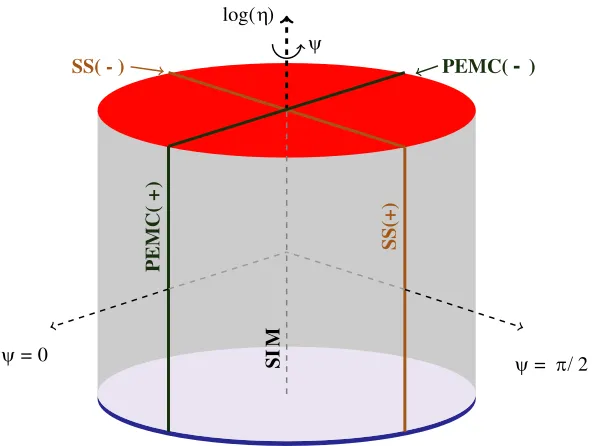
Figure 3 maps general unimodular bi-isotropic media into the volume of a circular cylinder. The simple isotropic (non-magnetoelectric) medium is mapped on the symmetry axis ranging from PEC (η = 0) to PMC (1/η = 0). The radial coordinate is ϑ, and the side of the cylinder at ϑ= π/2 leads to the SSA medium. There the special cases of PEMC (axion) medium (ψ = 0, π) and simple skewon medium ψ=π/2,3π/2 are mapped as the vertical lines ranging from PEC to PMC.
4.2. DH Versus DB Representation
log(η) ψ
ψ= π/2
ψ= 0 SIM
PEMC( +
)
SS(+)
PEMC( - )
SS( - )
Figure 3. The three-parameter unimodular bi-isotropic medium illustrated within a circular cylinder (parameters η, ϑ, ψ). The radial axis isϑ, and the side of the cylinder corresponds to ϑ=π/2.
The constitutive relation for unimodular bi-isotropic media with matrixMin Eq. (16) changes its form in this transformation:
D
H
= 1
η
cosϑ +e−jψsinϑ
−e+jψsinϑ cosϑ
E B
= 1
ηH
E B
(18)
Here the full matrix relation between D, H and E, B is no longer unimodular. However, the matrixH in Eq. (18) is unimodular, and it has also other interesting properties.
For real-valuedϑandψ, the matrixHisunitary; in other words its inverse is equal to its conjugate transpose. As a special case, for non-chiral materials (ψ = 0), H is a rotation matrix. A fundamental rotation isϑ=π/2 leading to the PEMC conditions (12) which “rotate” B toD and E to −H.
5. PROPERTIES OF UNIMODULAR MEDIA
5.1. Refractive Indices
The refractive index for a plane wave propagating in bi-isotropic unimodular media can be computed from the constitutive parameters as [5]
n±=
εrμr−χ2±κ (19)
For non-chiral materials (κ= 0), the refractive index is unity,n±= 1, and they are called unirefractive. Chiral media are birefringent; in other words the two eigenwaves have different propagation factors (n+=n−). Still, the conditionn+n−= 1 holds (cf. Eq. (9)).
Using the parameters ϑ, ψ, the refractive indices for unimodular media can be written in the form
n±= 1
cosϑ
1−cos2ψsin2ϑ±sinψsinϑ
(20)
An even more concise form comes, by using the inverse hyperbolic function:
n±= e±β, where β = arsinh(sinψtanϑ) (21)
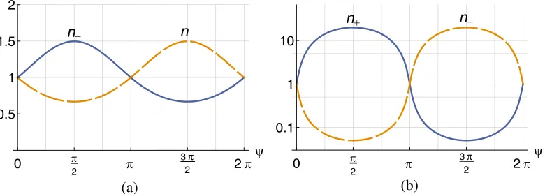
Figure 4 shows the variation of the two refractive indices as functions ofϑandψ. The birefringence (which vanishes for κ= 0, ψ= 0) is strongest for reciprocal media (χ= 0, ψ=±π/2) and it increases without limit when the medium approaches the SSA condition ϑ= π/2. It is also worth noting that
n+ n−
0 π
2 π
3π
2 2π
ψ 0.5
1 1.5 2
n+ n−
0 π
2 π
3π
2 2π
ψ 0.1
1 10
(a) (b)
Figure 4. Refractive indicesn± for unimodular bi-isotropic media as function of ψ. (a)ϑ=π/8, (b)
ϑ=π/2−0.1.
5.2. Duality Transformation
The duality transformation is a very important operation in electromagnetics, and its usefulness arises from the symmetry between electric and magnetic quantities in Maxwell equations [6]. The duality transformationDbetween the pair of electric and magnetic fields that leaves free space invariant is the
following:
E H
d
=D
E H
=
cosφ sinφ
−sinφ cosφ
E H
(22)
A natural question arises: how is a unimodular bi-isotropic medium affected by the duality transformation? Since the pair (D, B) also [6] transforms in duality with the same matrix D, we can write the transformed constitutive relation as
D B
d
=D
D B
=DM
E H
=DMD −1
Md D
E H
=Md
E H
d
(23)
The determinant of the transformed unimodular medium is
det(Md) = det(D)·det(M)·det(D−1) = det(M) = 1 (24)
because the determinant of the duality matrixDis unity. This leads to the conclusion that a unimodular bi-isotropic medium remains unimodular in the duality transformation.
6. CONCLUSION
The new class of materials defined and introduced in the present article, unimodular media, forms a fundamental subclass of bi-isotropic magnetoelectric materials. The definition of unimodular media — the requirement of unit determinant of the normalized material matrix — reduced the number of degrees of freedom of fully bi-isotropic media from four to three. The approach in the article showed that the essential qualities of unimodular media are condensed in the following three material parameters: the strength of impedance η, the degree of magnetoelectricity ϑ, and the angle of reciprocityψ.
The limiting cases of these parameters lead to fundamental electromagnetic material categories:
η= 0 corresponds to perfect magnetic conductor (PMC), 1/η = 0 to perfect electric conductor (PEC),
ϑ = ±π/2, χ = 0 to perfect electromagnetic conductor (PEMC) medium, ϑ = ±π/2, χ = ±π/2 to simple-skewon medium, and ϑ = 0 leaves us with the simple isotropic medium with unit refractive index.
Admittedly, the dimension of the space of electromagnetic materials is far higher than three. Possibilities to generalize the concept of unimodular media is straightforward by the definition (requirement that the determinant of the material matrix remain unity), but finding the essential physical quantities that span the emerging new dimensions is not. Attempts towards this direction are to find unimodular classes of bi-anisotropic materials and tri-isotropic materials [21].
REFERENCES
1. Frohlich, H., Theory of Dielectrics: Dielectric Constant and Dielectric Loss, Oxford University Press, 1987.
2. Milton, G. W., Theory of Composites, Cambridge University Press, UK, 2002.
3. Zouhdi, S., A. Sihvola, and M. Arsalane, editors, Advances in Electromagnetics of Complex Media and Metamaterials, NATO Science Series: II: Mathematics, Physics, and Chemistry, Vol. 89, 504, Kluwer Academic Publishers, Dordrecht, 2003.
4. Capolino, F., editor, Metamaterials Handbook, Theory and Phenomena of Metamaterials, CRC Press, Boca Raton, Florida, 2009.
5. Lindell, I. V., A. H. Sihvola, S. A. Tretyakov, and A. J. Viitanen, Electromagnetic Waves in Chiral and Bi-Isotropic Media, Artech House, Norwood, Massachusetts, 1994.
6. Lindell, I. V.,Methods for Electromagnetic Field Analysis, Wiley and IEEE Press, New York, 1995. 7. Sihvola, A.,Electromagnetic Mixing Formulas and Applications, IEE/IET Publishing, London, UK,
1999.
8. Lindell, I. V., A. H. Sihvola, and K. Suchy, “Six-vector formalism in electromagnetics of bi-anisotropic media,”Journal of Electromagnetic Waves and Applications, Vol. 9, No. 7/8, 887–903, 1995.
9. Born, M. and E. Wolf, Principles of Optics, 7th (expanded) Edition, Fourth printing, Cambridge University Press, 2006.
10. Goldstein, H., Classical Mechanics, 2nd Edition, Addison-Wesley, Reading, Mass., 1981.
11. Uslenghi, P. L. E., “Exact scattering by isorefractive bodies,”IEEE Transactions on Antennas and Propagation, Vol. 45, No. 9, 1382–1385, September 1997.
12. Sihvola, A. and I. V. Lindell, “PEMC, simple Skewon, and Minkowskian isotropic media: Classification of bi-isotropic metamaterials,” Proceedings of the XXXI General Assembly and Scientific Symposium of the International Union of Radio Science (URSI, 17–23 August 2014, Beijing, China, file BD01.5.pdf, https://doi.org/10.1109/URSIGASS.2014.6929220.
13. Lindell, I. V. and A. Sihvola, “Perfect electromagnetic conductor,” Journal of Electromagnetic Waves and Applications, Vol. 19, No. 7, 861–869, 2005.
14. Hehl, F. W. and Y. N. Obukhov, Foundations of Classical Electrodynamics, Birkh¨auser, Boston, 2003.
15. Paiva, C. R. and S. A. Matos, “Minkowskian isotropic media and the perfect electromagnetic conductor,”IEEE Transactions on Antennas and Propagation, Vol. 60, No. 7, 3231–3245, 2012. 16. Lindell, I. V., Differential Forms in Electromagnetics, IEEE Press and Wiley, Piscataway, NJ,
2004.
17. Lindell, I. V., Multiforms, Dyadics, and Electromagnetic Media, IEEE Press and Wiley, Hoboken, NJ, 2015.
18. Lindell, I. V. and A. Sihvola, “Simple skewon medium realization of DB boundary conditions,”
Progress In Electromagnetics Research Letters, Vol. 30, 29–39, 2012.
19. Deschamps, G. A., “Electromagnetics and differential forms,” Proceedings of the IEEE, Vol. 69, No. 6, 676–696, June 1981.
20. Sihvola, A. H. and I. V. Lindell, “Bi-isotropic constitutive relations,” Microwave and Optical Technology Letters, Vol. 4, No. 8, 295–297, July 1991.