Power Quality Problems Reduction Using an Dvr Device
With Solar System
Yerrabelliprathapkumar
Assistant Professor Department Of Eee Khammam Institute Of Technology And Sciences Khammam, Telangana 507170, India.
Abstract: Presently a days in the
appropriation system the renewable energy sources significance has been increased. In this paper an interline dynamic voltage restorer (IDVR) has proposed for the dispersion systems to moderate voltage droop/swell issues and also enhance power quality. All in all for the typical voltage levels, the DVRs ought to be skirted ,however instead of bypassing the DVRs, this paper proposes new operating plan for the DVRs, if necessary, to enhance the displacement factor (DF) in any of the involved feeders. For the most part an
interline dynamic voltage restorer
comprises of a few dynamic voltage restorers (DVRs) with a sharing dc link. IDVR is associated with the independent feeders to secure the electric power to the basic loads. One of the DVRs makes up for the neighbourhood voltage hang in its feeder, and alternate DVRs renew the regular dc-link voltage is provided by using solar energy (PV). DF improvement can be accomplished through active and reactive power trade (PQ sharing) between various feeders. To approve the proposed system, Simulation comes about have been displayed using MATLAB/SIMULINK programming.
Keywords: PV System, Displacement Factor Improvement, IDVR, IVDFC, PQ Sharing Mode.
I. INTRODUCTION
Dispersion systems are generally inductive at the principal recurrence in view of the idea of the dominant associated loads (e.g., induction engines). This, in turn, decreases the displacement factor (DF) and spots an
extra weight on the electrical supply. Low DF operation isn't prescribed because of a few negative impacts on the power system including:
● Higher current for a given active power
and a corresponding increase in absolute
copper misfortune (i.e., system
effectiveness diminish);
● lower use of power system parts;
● Voltage control issues and rising power
conveyance costs.
A few useful techniques are generally used to enhance DF. DF improvement employing capacitor manages an account with size and area enhancement has been introduced in. The ideal area and size of the capacitor bank to be set in outspread conveyance feeders to enhance their voltage profile and to diminish the aggregate energy misfortune are exhibited in [3]. Distinctive techniques are utilized in [4] to minimize the power misfortune in conveyance systems. In [5],
the feeder reconfiguration idea in
dissemination systems is introduced to decrease system misfortune. In [6], a
combined system for symphonious
low-space necessity, and great security margins. As of late, it is quickly replacing the customary normally commutated reactive
power controllers and static VAR
compensators. The reactive power provided by the STATCOM for DF improvement is capacitive in nature. Intuitively, the higher the STATCOM's reactive power, the higher the dc-link voltage of the STATCOM (the higher the voltage prerequisites of the semiconductor gadgets).The DVR is a standout amongst the most widely recognized and powerful answers for protecting basic loads against voltage droop. The DVR is a power electronic gadget used to inject three-phase voltages in arrangement and in synchronism with the circulation feeder voltages keeping in mind the end goal to make up for voltage lists. Additionally, it can be adequately used to upgrade the blame ride through capacity in wind applications. Location time is a vital factor in the voltage reclamation process. In circulation systems, load voltage rebuilding can be accomplished by injecting active as well as reactive power into the appropriation feeder. Active power ability of the DVR is administered by the limit of the energy stockpiling component and the utilized remuneration technique. A few control techniques have been proposed for voltage droop pay, for example, pre-list, in-phase, and minimal energy control approaches. In the event that the required power for voltage reclamation is obtained from the neighboring feeder(s), the compensating gadget is actually called an interline dynamic voltage restorer (IDVR). The fundamental idea driving the IDVR is gotten from the interline power stream controller (IPFC) proposed by Gyugyi in 1999 to trade power between parallel transmission lines. The two converters of the IPFC appeared in Fig. 1 are utilized to control the transmitted power in each line (P1 and P2 ) and active power exchange between lines (P12). Concerning the line current, the injected voltage has two segments. The quadrature segment gives
Fig.1. Single line diagram of an IPFC in transmission system.
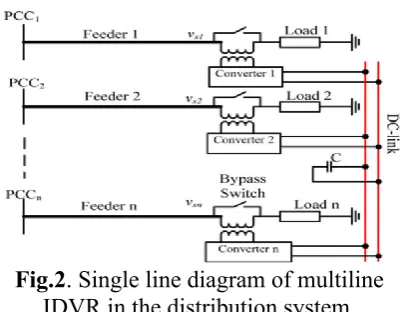
During ordinary operating conditions (i.e., all feeders are sound), the DVRs are regularly skirted by means of sidestep switches, or they can be then again utilized for load sharing purposes as exhibited in [26]. Instead of bypassing the IDVR in ordinary operation, this paper proposes another operational mode, to be specific PQ sharing mode, to enhance the DF of one of the involved feeders by sharing active and reactive power among various system feeders through the buffering stage (the basic dc link). To apply this idea, a few constraints are watched all through the paper. The proposed interline dynamic voltage restoring and DF controlling gadget (IVDFC) is bolstered using recreation comes about.
Fig.2. Single line diagram of multiline IDVR in the distribution system.
Fig. 3 PC mode.
TABLE I: Salient Features of the IPFC, IDVR, And IVDFC
II. TWO-LINE IVDFC SYSTEM IN NORMAL OPERATION
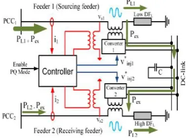
Like the IDVR, the two-line IVDFC essentially comprises of two voltage source converters associated consecutive with a typical dc link, as appeared in Fig. 4. For typical voltage levels, achieving active power trade Pex between the feeders (from sourcing feeder to receiving feeder), requires controlled voltage injection in every feeder by the corresponding converter (see Fig. 4). This injected voltage ought not irritate the load voltage size of the two feeders; along these lines, the two converters are operating under PC mode.
A. Sourcing Feeder
means of injecting a controlled voltage
(greatness and phase) through the
arrangement coupled transformer allowing for power trade. In this paper, keeping in mind the end goal to imitate the impact of voltage injection on the feeder DF, the injected voltage is copied using a voltage drop crosswise over arrangement virtual impedance, as appeared in Fig. 5(a). The resistive part of this virtual impedance assimilates active power (Pex) from the source, while the capacity of the capacitive reactance segment is to maintain a consistent load voltage extent. After voltage injection, the supply's active power increases while it's reactive power diminishes because of the virtual injected
capacitive reactance, henceforth, the
sourcing feeder DF in the long run increases. Assuming a three-phase adjusted load is associated with the feeder; the per-phase proportional circuit of the feeder with arrangement virtual impedance injection is appeared in Fig. 5(a), while the corresponding phasor outline is appeared in Fig. 5(b).
Fig. 4. Principle of IVDFC system operation during normal conditions (PQ sharing mode).
For a given transferred active power Pex (through dc link), the load power is given by
(1)
As indicated in the phasor diagram shown in Fig. 5(b), the supplied power is given by
...(2)
Fig. 5 sourcing feeder: (a) per-phase equivalent circuit with virtual impedance injection and (b) corresponding phasor diagram.
Where Pex is the power absorbed from the
source and pumped into the dc link. From (2), the angle β1 can be obtained as follows:
(3)
The maximum allowable Pex corresponds to
unity input DF. For a given load DF, the
maximum Pex is given by
The virtual injected resistance r1, which represents absorbed active power from sourcing feeder, is given by
(5)
From the phasor diagram shown in Fig. 5(b), the virtual injected capacitive reactance x1 is given by
(6)
For any measure of wanted traded active power (Pex ) and load-side parameters (I1, V1 , and DFL 1 ), the voltage source converter at the sourcing feeder injects this power to the dc link without affecting load voltage greatness by supplying a voltage of size 2V1 sin (β1/2). This present voltage's phase point slacks the supply voltage phase edge by (π − β1)/2, as appeared in Fig. 5(b).
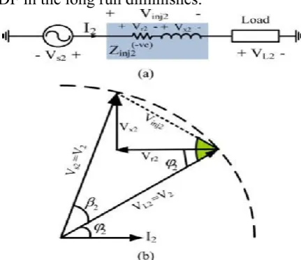
B. Receiving Feeder
The converter in the receiving feeder is in charge of absorbing the transmitted power from the sourcing feeder through voltage injection; consequently, the power controller
has a power summon of−Pex. The injected
voltage for this situation is identical to
injecting a virtual negative protection −r2 in
arrangement with an inductive reactance x2,
as appeared in Fig. 6(a). From the identical circuit and the phasor chart appeared in Fig. 6(a) and (b), the point β2 is given by
... (7)
To ingest this measure of exchanged active power without affecting the load voltage greatness, the injected voltage in the receiving feeder ought to have a size of 2V2 sin (β2/2), and its phase point drives the supply voltage phase edge by (π − β2 )/2. It is important that the supply's active power
diminishes while its reactive power increases because of the virtual injected inductive reactance, i.e., the receiving feeder DF in the long run diminishes.
Fig. 6receiving feeder: (a) per-phase circuit with virtual impedance injection and (b) corresponding phasor diagram.
C. PQ Sharing Mode for DF
Improvement during Normal Operation
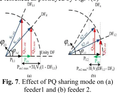
power Pex is exchanged from feeder 1 to feeder 2, with the end goal that its DF achieves a certain coveted esteem DFd , as appeared in Fig. 7(a), the DF of feeder 2 will be lessened, as portrayed by Fig. 7(b)
Fig. 7. Effect of PQ sharing mode on (a) feeder1 and (b) feeder 2.
The sourcing feeder DF can be enhanced to DFd, if and just if, the required active power Pex to accomplish this condition is not as much as the required power to diminish the receiving feeder's DF to the acknowledged DF constrain DFa. In the event that this condition isn't fulfilled, the DF of the sourcing feeder will be enhanced, however it won't achieve the coveted level, and the receiving feeder DF will be constrained to its satisfactory level. Consequently, the reference active power (Pex) during PQ sharing mode is given by
...(8)
This control is defined as the minimum of two terms; the primary term gives the required increment in sourcing feeder provided active power to enhance its DF to a coveted level DFd, while the second term gives the required decrement in receiving feeder provided active power to lessen its DF to the acknowledged esteem DFa. In the event that the receiving feeder's active power is higher than that of the sourcing feeder, a slight variety in its DF introduces an observable improvement in sourcing
feeder DF. For the most part, the DF improvement will lessen the greatness of currents in the up-stream branches of the grid, i.e., diminish grid misfortunes. It must be noticed that, in the proposed technique, the DF is enhanced by reducing the contrast between supply voltage and current phase edges assuming a consistent volt-ampere condition. Thus, the work of PQ sharing mode won't influence the feeder misfortunes since the current extents are kept steady, yet converters misfortunes will be added to the feeder misfortunes to speak to the aggregate misfortunes of the system (from points of basic coupling to load feeding points).
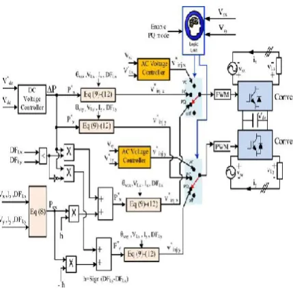
III. OVERALL SYSTEM CONTROLLER
.
Fig. 8. Proposed controller.
The following segment will demonstrate how extraordinary modes of operation are taken care of individually in the proposed controller. An arrangement of situations can be imagined for the system. The main cases are condensed in Table II and in the
following subsections (where the
hyphenated condition depicts the condition of one of the feeders to one side of the hyphen and the other feeder to one side of the hyphen). For every single other case, the converters will be changed to the off position.
A. Normal–Normal (PQ Sharing Mode is disabled)
In this case, the logic unit selects the off positions (see Fig. 8) for both converters.
B. Normal–Normal (PQ Sharing Mode is enabled)
For this situation, the rationale unit chooses the PQ positions (see Fig. 8) for the two converters in the wake of verifying all constraints that go with this mode. In light of the DFs of the loads associated with the involved feeders (DFLx and DFLy), the bearing of active power stream will be defined. The feeder with a lower load DF will be the sourcing feeder with a positive
active power reference, and the other feeder will be the receiving feeder with a negative active power reference. In Fig. 8, the indication of the variable h, which speaks to the distinction between the two DFs, is utilized to determine the indication of the diverse reference powers. To maintain a steady dc-link voltage during the PQ sharing mode, the output of the dc link voltage controller, ΔP (which speaks to the active power expected to direct the dc link) is added to the reference active power of the sourcing feeder. To accomplish that, the two DFs (DFLx, and DFLy) are contrasted with choose the sourcing and receiving feeders. The comparator output is utilized to add ΔP to the reference active power of the sourcing feeder just as appeared in Fig. 8. For instance, if DFLx is not exactly DFLy, the comparator output will be high; in this way,
ΔP will be added to Pex (i.e., P*x = Pex+ΔP and P*y = − Pex). The voltage reference of every converter is then determined in light of the corresponding active power references (P*x and P*y) as given by (9)– (12), where I = x or y
(9)
(10)
(11)
(12)
C. Normal–Voltage Sag
arrangement converter to VC position (see Fig. 8) to manage the load voltage, and the required power for reclamation will be consumed from the dc link. The converter of the solid feeder will be changed to its PC position (see Fig. 8) to renew the dc-link voltage. The required power to reestablish the dc link voltage will be the output of the dc voltage controller. This power is utilized to appraise the corresponding converter reference voltage.
D. Normal–Voltage Swell
On the off chance that one feeder shows voltage swell, the rationale unit switches its arrangement converter to the VC position (see Fig. 8) to direct the load voltage. Extra power is then nourished to the dc link. The converter of the sound feeder will be changed to its PC position (see Fig. 8), to abstain from increasing the dc-link voltage. The measure of power, which ought to be consumed by the sound feeder, will be the output of the dc voltage controller. In this paper the proposed system with PV can control the voltage unbalances like voltage lists, swells and so forth. The displacement factor will be enhanced by active and reactive power sharing between the feeders by a DC link, which is controlled by PV system. This system makes the significance of renewable systems at appropriation division.
TABLE II: Proposed Controller
Combinations
IV. SIMULATION RESULTS
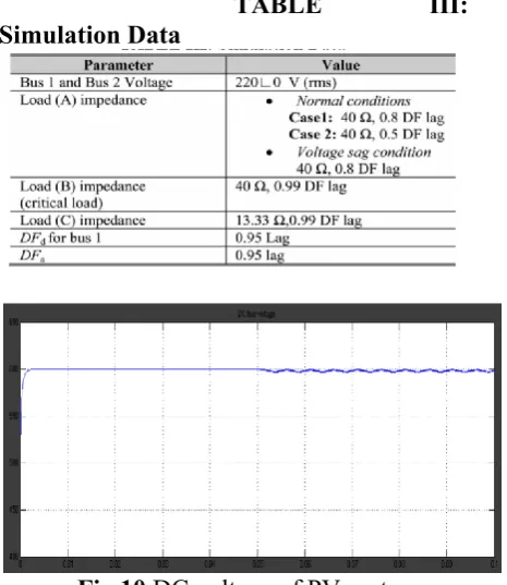
Fig.9 shows simulink diagram of proposed IVDFC with PV system. Fig 10 shows DC voltage of PV system.
Fig.9. simulink diagram of proposed IVDFC with PV system.
TABLE III:
Simulation Data
Fig 10 DC voltage of PV system.
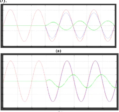
active power order (Pex ) is computed in view of (8). For the information given in Table III, the measure of active power expected to increase the DF of the sourcing (feeder 1) from 0.8 lagging to 0.95 lagging is ≈544.5 W (3 (220 V ×(220/40)A × (0.95 − 0.8))). Then again, the measure of active power expected to diminish the DF of the receiving (feeder 2) from 0.99 lagging to 0.95 lagging is ≈580.8 W (3 (220 V × (220/10)A × (0.99 − 0.95))), i.e., Pex ought to be the minimum of these two esteems (544.5, 580.8). Thus, the controller sets Pex to 544.5 W. This esteem is connected to the controller at t = 0.05 s. The injected, supply voltage and supply current of transports 1 and 2 are in Fig. 11(a) and (b), individually. At the point when the PQ sharing mode is connected, the phase contrast between the supply voltage and current of transport 1 is diminished, i.e., DF of transport 1 is moved forward. Then again, the phase contrast between the supply voltage and current of transport 2 is somewhat increased, i.e., its DF is diminished. The DF of each transport when applying the PQ sharing mode is appeared in Fig. 11(c). The recreation brings about this case are abridged in Table IV. By and large, it indicates slight variety in DF of transport 2 while the DF of bus1 is enhanced from 0.8 to 0.95 lagging effectively.
.TABLE IV: Effect of Applying PQ Mode In Simulation
Fig.11. Per-phase PQ sharing mode simulation results: (a)–(c) for first case. Mitigation of Power Quality Problems Using an Improved Interline Dynamic
Voltage Restoring Devi
ce with PV System
Fig. 12 Per-phase PQ sharing mode simulation results: (d)–(f) for the second case.
Case 2: For this situation, load (A) has a lower DF contrasted with the previously mentioned case (0.5 lagging instead of 0.8 lagging).The measure of active power expected to increase the DF of the sourcing feeder from 0.5 lagging to 0.95 lagging is 1633.5 W (3 (220 V × (220/40)A × (0.95 − 0.5))). Then again, the measure of active power expected to diminish the DF of the receiving feeder isn't changed (580.8 W), i.e., Pex ought to be the minimum of these two esteems (1633.5, 580.8). Subsequently, the controller sets Pex to 580.8 W. This esteem is connected to the controller at t = 0.05 s. The injected, supply voltage and supply current of transports 1 and 2 are in Fig. 12(a) and (b), individually. The DF of each transport when applying the PQ sharing mode is appeared in Fig. 12(c). The recreation comes about for this case are likewise outlined in Table IV. For the most part, it demonstrates that the DF of transport 1 is enhanced from 0.5 to 0.66 lagging; henceforth, reaching the coveted esteem was impractical since the DF of the receiving feeder achieved its minimum acknowledged level (DFa ) as appeared in Fig.13(a) and (b).
Fig. 13. Per-phase simulation results for voltage sag case: (a) at feeder 1 and (b) at feeder 2.
V. CONCLUSION
This paper proposes another operational mode for the IDVR to enhance the DF of various feeders under typical operation. In this mode, the DF of one of the feeders is enhanced by means of active and reactive power trade (PQ sharing) between feeders through the basic dc link is provided by using solar energy (PV). A similar system can likewise be utilized under strange conditions for voltage hang/swell relief. Under PQ sharing mode, the injected voltage in any feeder does not influence its load voltage/current greatness, in any case, it influences the DFs of both sourcing and receiving feeders. From the outcomes it can watched that the PQ sharing will be done between the feeders using PV system by means of normal DC link capacitor. In the uneven conditions like droops/swells the PV system maintained the system adjusted and by maintaing steady DC voltage at the regular DC link capacitor. The proposed mode is exceedingly valuable if the active power rating of the receiving feeder is higher than the sourcing feeder. The DF of the sourcing feeder increases while the DF of the receiving feeder diminishes. While applying the proposed idea, a few constraints ought to be fulfilled to maintain the DF of both sourcing and receiving feeders within satisfactory breaking points forced by the service organizations. These
operational constraints have been
recognized and considered. For this situation, the DF of the sourcing feeder will have a prominent improvement with just a slight variety in DF of the receiving feeder.
VI. REFERENCES
[1] Ahmed Elserougi, Ahmed M. Massoud ,’’ An interline Dynamic voltage restoring
and Displacement factor controlling
device,’’ IEEE Trans. Power Del., vol. 29, no. 6, pp. 1922–1933, Oct. 2014.
IEEE Trans. Power App. Syst., vol. PAS-100, no. 3, pp. 1105–1118, Mar. 1981. [3] S. M. Kannan, P. Renuga, and A. R. Grace, “Application of fuzzy logic and particle swarm optimization for reactive power compensation of radial distribution systems,” J. Electr. Syst., 6-3, vol. 6, no. 3, pp. 407–425, 2010.
[4] L. Ramesh, S. P. Chowdhury, S. Chowdhury, A. A. Natarajan, and C. T. Gaunt, “Minimization of power loss in
distribution networks by different
techniques,” Int. J. Electr. Power Energy Syst. Eng., vol. 3, no. 9, pp. 521–527, 2009. [5] T. P.Wagner, A. Y. Chikhani, and R. Hackam, “Feeder reconfiguration for loss reduction: An application of distribution automation,” IEEE Trans. Power Del., vol. 6, no. 4, pp. 1922–1933, Oct. 1991.
[6] A. Luo, Z. Shuai,W. Zhu, and Z. J. Shen,
“Combined system for harmonic
suppression and reactive power
compensation,” IEEE Trans. Ind. Electr., vol. 56, no. 2, pp. 418–428, Feb. 2009. [7] S. B. Karanki, N. Geddada, M. K.
Mishra, and B. K. Kumar, “A
DSTATCOMtopology with reduced DC link voltage rating for load compensation with nonstiff source,” IEEE Trans. Power Electr., vol. 27, no. 3, pp. 1201– 1211, Mar. 2012. [8] K. Sano and M. Takasaki, “A transformerless D-STATCOM based on a multivoltage cascade converter requiring no DC sources,” IEEE Trans. Power Electr., vol. 27, no. 6, pp. 2783–2795, Jun. 2012. [9] B. Singh and S. R. Arya, “Adaptive theory-based improved linear sinusoidal tracer control algorithm for DSTATCOM,” IEEE Trans. Power Electron., vol. 28, no. 8, pp. 3768–3778, Aug. 2013.
[10] S. Du, J. Liu, J. Lin, and Y. He, “A novel DC voltage control method for STATCOM based on hybrid multilevel H-bridge converter,” IEEE Trans. Power Electr., vol. 28, no. 1, pp. 101–111, Jan. 2013.
[11] B. Singh and S. R. Arya, “Adaptive theory-based improved linear sinusoidal
tracer control algorithm for DSTATCOM,” IEEE Trans. Power Electr., vol. 28, no. 8, pp. 3768–3778, Aug. 2013.
[12] R. S. Kemerer and L. E. Berkebile,
“Directly connected static VAR
compensation in distribution system
applications,” IEEE Trans. Ind. Appl., vol. 35, no. 1, pp. 176–182, Jan./Feb. 1999
Authors Profile
YERRABELLIPRATHAPKUMAR, he
obtained his M.Tech in the stream of Power Electronics from JNT University Hyderabad in 2013.He obtained his B.Tech in the stream of Electrical and Electronics
Engineering from JNT University
Hyderabad in2010.He has the teaching experience of over 4 Years. He has also guided more than 4 M.Tech and 10 B.Tech Projects.His areas of interest are power
systems and Analysis, HighVoltage