Available online:
http://edupediapublications.org/journals/index.php/IJR/
P a g e | 8 2DESIGN OF COST EFFICIENT VIRTUAL FILTER
USING LabVIEW PLATFORM
G.Shanmugaraj
1, V.Sai Lakshmi Sruthi
2, R.Golde
4& R.S.Adlin Beryl
31 ,2 ,3 ,4
Electronics and Communication Engineering
1 ,2 ,3 ,4Velammal Institute of Technology
A bs tract :
As the demand for compact and high speed digital signal processing (DSP) systems is increasing with a explosive growth in the portable multimedia and mobile computing application ,there is a severe need in designing the filter with more user-friendly features like accuracy, versatility, stability, low power consumption, and efficiency. In digital worlds, the signal comes coupled with noise interruptions. To get rid of this unwanted noise, we use filters. Note that sometimes filters not only remove the unwanted signals but also some parts of the signal itself. Noise reduction is a process of removing noise in original signals. We are implementing the noise reduction filter on lab view which is a platform and development environment for a visual programming language to design virtual filter. Here we designed a filter to enhance the process of noise reduction and implemented on labview platform to get exact output value from the waveform added with noise. This paper primarily deals with designing of a virtual filter using the LabVIEW development platform. Firstly the primary goal of the study represents the designing and implementation of a low power and high speed virtual filter. Secondly it includes the optimization of filter area and delay constraints. The effectiveness of the proposed algorithm is explained by comparing the results with the study of other filter algorithms. On an average, the proposed algorithm saves about 20.9% to 72.7% of area and power consumption of a filter bank designed for feature extraction of signals by 33.9% to 54.8% over the competing algorithms.
Keywords :Digital signal processing, efficiency, low
power consumption, high speed, filter algorithm.
1.
Introduction
Filters are an important part of electronic circuits today. Whether it is the analogue or digital world, the role of filters is very important. The source of digital signal filtering techniques can be traced back to the seventeenth century after the finite difference recent
arithmetical power is given to us, the ability to manipulate the terrific amount of data in real time. Digital filtering is useful in a range of applications like speech recognition, medical image processing, etc. The FIR filters are the fundamental component of several digital signal processing algorithms. So, here we are doing the filtering of noise using FIR filter on a LabVIEW. LabVIEW offers a graphical programming approach that helps you visualize every aspect of your application, including hardware configuration, measurement data, and debugging. This visualization makes it simple to integrate measurement hardware from any vendor, represent complex logic on the diagram, develop data analysis algorithms, and design custom engineering user interfaces.The optimization of the area, power, and delay in digital circuit is very efficient. MATLAB has become the standardized software and inevitable way of visualization of DSP theory for a long time. But here the LabVIEW (Laboratory Virtual Instrument Engineering Workbench) Platform has nothing to do with the programming for designing a filter.
LabVIEW is a special platform that has been designed to view the filter design in a graphical way. This software platform is a graphical developing environment with built-in functionality for data acquisition and presentation, instrumentation, measurement analysis and simulation. The graphic applications of LabVIEW are called “virtual instruments” as their look and functions imitate the real instruments and they consist of great number of library functions which are used for creating applications for solving set of task in Digital Signal Processing (DSP) systems.
Available online:
http://edupediapublications.org/journals/index.php/IJR/
P a g e | 8 3meet the application requirements, and it has strong practicability. The system not only generates the signal, it also processes and filters out the noise signal.
Figure1: LabVIEW filter palette
The following sections deal with the functions of the various blocks in the virtual filter design, also gives a clear view of how the noise signal is superimposed on the input signal and the signal processing takes place to provide the pure signal by eliminating the unwanted frequencies in the signal and to obtain the original input signal with higher efficiency at lower cost.
2.
Filter Design
2.1.Domain Introduction
Digital signal processing (DSP) is the use of digital processing, such as by computers or more specialized digital signal processors, to perform a wide variety of signal processing operations. The signals processed in this manner are a sequence of numbers that represent samples of a continuous variable in a domain such as time, space, or frequency. Digital signal processing and analog signal processing are subfields of signal processing. DSP applications include audio and speech processing, sonar, radar and other sensor array processing, spectral density estimation, statistical signal processing, digital image processing, signal processing for telecommunications, control systems, biomedical engineering, and seismology, among others. If we strip away the DIGITAL from Digital Signal Processing, we are left with something that we’ve been doing in electronics since it was first invented, Signal Processing! Signal processing is all about taking a signal, applying some change to it, and then getting a new signal out. That change might be amplification or filtration or something else, but nearly all electronic circuits can be considered to be
signal processors. Looked on in this way, the signal processor as a black box might be composed of discrete components like capacitors and resistors, or it could be a complex integrated circuit with many circuits to accomplish a more complex task, or it could be a digital system which accepts a signal on its input and outputs the changed signal. So long as it accomplishes its defined task, it doesn’t matter how the box works internally.
Digital signal processors require several things to work properly:
1. A processor fast enough and with enough precision to support the mathematics it needs to implement.
2. Supporting memory to store programming, samples, intermediate results, and final results.
3. Analog-to-Digital (A/D) and Digital-to-Analog (D/A) Converters to bring real signals into and out of the digital domain. 4. Programming to do the job.
Digital signal processors, even single chip DSP systems, are built from these elements. Twenty years ago, anyone using DSP had to be quite a mathematician to be able to implement and use the algorithms. It is generally proprietary as well, but the basics of how DSP works are simple enough to understand. While you won’t be able to implement your own algorithms after reading this, you will know a little more about how DSP works. The design of virtual filter includes basic signal generator, noise signal, super imposed signal, window function, filter processing, waveform display and other modules. The structure of the block diagram can be clearly viewed in the following figure 2.
Figure2: Block diagram of virtual filter
Available online:
http://edupediapublications.org/journals/index.php/IJR/
P a g e | 8 4The main modules of the filter design are: signal generation module, window function module and the filter module.
2.2.1. Signal Generating Module
The signal generator helps to generate repeating or non-repeating signal either in analog or digital form. The signal generator is an electronic device and is generally used in designing, testing, troubleshooting, and repairing electronic devices. There are different signal generators with different purposes and application, at different levels of expense. The different generators are: RF and microwave signal generators, pitch generators, digital and analog pattern generators, arbitrary waveform generators and frequency generators. Here we use analog wave pattern signal generator in the design of the virtual filter. Design of signal generator can automatically change the signal frequency, offset phase, amplitude, accounted for empty ratio values, at the same time inorder to ensure the branches of condition and does not cause repeated cross reference, the produced frame diagram is showed in figure 4.Signal generator with conditional branch structure is selected to simulate variety of signals including sine wave, square wave, saw tooth wave, triangular wave etc,. The conditional branching program block diagram is shown in the Figure 3.
Figure 3: Waveform type of conditional branch
Figure 4: Input signal parameters
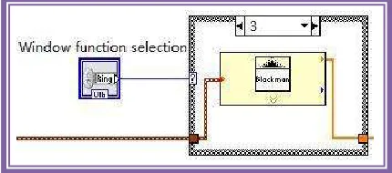
2.2.2. Window Function Module
The tapering function is the other name that is used to mention the window function, which is a mathematical function that is zero-valued outside of some chosen interval. For example, considering a rectangular window function, the function is constant inside the interval and zero elsewhere, this helps to describe the shape of rectangular window function in graphical representation.
In non-negative, smooth, “bell-shaped” curves. Rectangle, triangle, and also in other functions the window module can be used. Windows are used in the design of digital filters, in particular to convert an ideal impulse response of infinite duration, such as sinc function to a finite impulse response filter design. This is called the window method. In accordance with the analysis of nature of the signal and processing requirements one can choose the window function module as shown in the figure 5.
Figure 5: Window function module
2.2.3. Filter Module
A filter is a device or process that removes unwanted components or undesired frequencies or features from a signal. Electronics and telecommunication, radio, television, radar, control systems, image processing and computer graphics are the different fields in which filtering concepts takes its application. The filters may be:
Linear or non-linear
Time invariant or variant(also known as shift invariance)
Casual or non-casual
Analog or digital
Infinite impulse response or finite impulse response
Passive or active
Available online:
http://edupediapublications.org/journals/index.php/IJR/
P a g e | 8 5Figure 6: Filter module
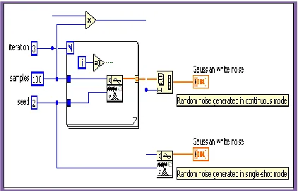
2.2.4. White Gaussian Noise
The Central Limit Theorem is one reason why Gaussian noise is so important as a model. That Gaussian noise is completely described by second order statistics, which are relatively easy to measure. E.g., if you have a univariate distribution and if it is Gaussian, then you know everything you can ever know about it by knowing (measuring) its mean (first order) and its variance (second order). There are no higher order statistics, which is good because they are much harder to measure reliably. This fact is of course no justification for using a Gaussian model, but it is a very handy property if we think that a Gaussian model is justified.
3.
Block Diagram and Front Panel view of
LabVIEW
Above all the sub module, the virtual filter can get the front panel and block diagram as shown in Figure 7, 8. The front panel of the design is divided into three zones, which are the input signal parameter setting area, the waveform display area, the window function selection and filter parameter setting area. Set in the input signal parameters, use a drop-down list to select text control signal input type, frequency and amplitude were used to control the two "knob" to set the input signal, phase, four numerical input control to set the input signal for noise ratio, offset,
Gauss white the noise of the poor, a numerical display control to set the custom signal formula; waveform display area has four waveforms, respectively, to display the input signal and noise signal, the input signal and noise signal, the superposition of the filtered signals; set in the window function selection and filter parameters, use a drop-down text the list of controls to select the type of window function, respectively, with two control knob to set the level of filter cut-off frequency, two numerical control to set the input filter Number and noise signal parameters. The front panel of the virtual filter and the block diagram of the virtual filter are clearly described in the given following figure.
Figure 7: Front panel of virtual filter in LabVIEW platform
Figure 8: Block diagram view of virtual filter in LabVIEW platform
4.
Virtual Filter Signal Processing Test
Available online:
http://edupediapublications.org/journals/index.php/IJR/
P a g e | 8 6our digital system as a stream of samples, we can now process them in a variety of ways. This is where the math gets complicated and we have a real need to know about the mathematics. However, if what needs to be done is simple enough so that it can be done with existing DSP chips, we may not need to know any of the complex mathematics ourselves, leaving it to the chip designers to make the math work right. If you’re doing something special though, then even with DSP chips, you’ll need to be skilled enough to know what can be done and what cannot. The superimposed signal is further sent to the window function module and the signal finishes the filtering process and the original form of the signal is obtained at the end of the process, after removing the unwanted noise using the filter. The waveforms are displayed at each stage of the signal processing for better understanding of the signal. The following figures 9-11 represent the waveforms before and after the filtering process.
Figure 9: Blackman window processing filter
Figure 10: Chebyshev window processing filter
Figure 11: Hanning window processing filter
5.
LabVIEW
LabVIEW is a programming environment and system design tool for a visual programming language, developed by American company National Instruments.
5.1.
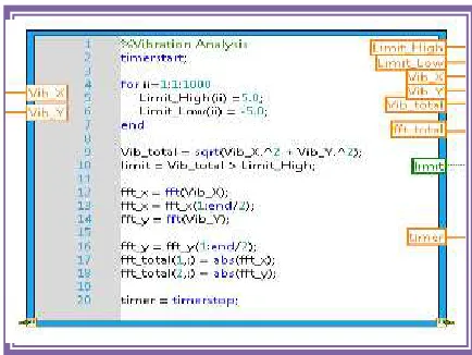
The Language
LabVIEW differs from most other development platforms in the regard that it depends on ‘visual programming’ more than actual coding. In simple words, you use either predefined or custom components to complete programming tasks. For example, to create a reiterating series, all you need to do is drag and drop the corresponding loop functionality onto the block diagram. Add your conditions, outputs, connections, and you’re good to go!
Figure 12: Sample module for LabVIEW Language
5.2.
The Programming
Available online:
http://edupediapublications.org/journals/index.php/IJR/
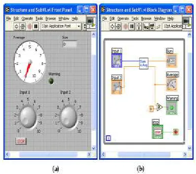
P a g e | 8 7types, so depending on application, you can use any one, or multiple, for that matter! The beauty of LabVIEW lies in the fact that simple components and functions can be strung together to create complex programs and interfaced to devices. An expert LabVIEW programmer should have extensive knowledge of all its syntax, topology, functions and components, only then can he or she get the most out of it. As we mentioned earlier, it seems deceptively easy at first, but is difficult to master.
Figure 12(a)(b): The program design modules of LabVIEW
Once you’ve placed your main components, the block diagram is where you actually make all the connections and add functions. The components placed in the front panel appear in your block diagram as well, so all you have to do is add your functional components and connect them together to achieve output. Any errors will be highlighted and explained before you run it, and custom circuits can also be saved as user functions.
6.
Limitations
The limitation of the filter design depends upon the type of filter that is chosen. The advantages and disadvantages vary from filter to filter. For instance, the advantage of IIR filters over FIR filters is that IIR filters usually require fewer coefficients to execute similar filtering operations, that IIR filters work faster, and require less memory space. The disadvantage of IIR filters is the nonlinear phase response. IIR filters are well suited for applications that require no phase information, for example, for monitoring the signal amplitudes. FIR filters are better suited for applications that require a linear
phase response. Similarly in the case of analog and digital filters, the analog filters are costly compared to the digital filters based upon the analog components used. Latency in analog filters is low compared to the digital filters. Hence proper filter must be chosen based on the application requirements.
6.1.
Existing System
In existing system, the butterworth filter is used as filter to reduce noise. IIR filters are not stable as they are recursive in nature and feedback is also involved in the process of calculating output sample values.
6.1.2.
Disadvantages
IIR filters is the nonlinear phase response
Efficient only on monitoring the signal amplitudes
6.2.
Proposed System
In our proposed system we used FIR (finite impulse response) because of its linear phase response and also they are non-recursive. Feedback is not involved in FIR, hence they are stable. The signal generator generates the signal which is added to the white noise and then applied to the window function. The purpose of window functions in signal processing is to remove (hopefully) extraneous information and finally we send the signal to the FIR filter to get original signal.
6.2.1.
Advantages
FIR filter consume low power
They are simple to implement.
They are suited to multi-rate applications
7.
Conclusion
Available online:
http://edupediapublications.org/journals/index.php/IJR/
P a g e | 8 8Digital filters are becoming ubiquitous in audio applications. As a result, good digital filter performance is important to audio system design. The major difference of digital filter over analog filter is their use of finite precision to represent signals and coefficients and finite precision arithmetic to compute the filter response. The above proposed filter process can help to rectify the noise signal and to extract the original signal as final result. The usage of LabVIEW platform helps to reduce the cost of filter design and also the filter helps to improve the filter performance with high efficiency. This paper helps to design a graphical view of the filter prior to the hardware design and then can be implemented into the real time systems.
8.
References
[1] Zhou Xifeng, Hu Xiaodong, He Xiaomin. Design and implementation of Virtual Arbitrary Waveform Generator and oscilloscope. Journal of Hunan Institute of Engineering, 2016, 26 (1): 19-24.
[2] Pan Fengqun, Yang Jianqiao, Zheng en. The design and implementation of virtual digital filter based on. LABVIEW electronic measurement technology, 2012, 35 (3): 78-81.
[3] Yang Shifeng, Wang Donghui,ZhaoMeng. Tire equipment monitoring system based on LabVIEW and AB control technology. Proceedings of the Fourth International Symposium on Test Automation & Instrumentation, 2012.
[4] Zou Ling and Guo Biao, Chu Sihong. Based on LabVIEW digital IIR filter design. Journal of Hubei University of technology, 2011,26 (4): 77-82. (3): 83-84.
[5] Li Yunming, Liu Qihe.LabVIEW virtual instrument program design and application [M]. Beijing: Chemical Industry Press, 2011.
[6] Tian Hao, DuanLijun. Design of multifunction digital filter based on. LabVIEW electronic measurement technology, 2011,34 (3): 66-70.
[7] A.P.Chandrakasan and R.W.Broderson, “Minimizing power consumption in digital CMOS circuits,”proc IEEE, pp.498-523,Apr.1995.
[8] M.Mehendale,S.D.Sherlekar, and G.Venkatesh,”Low-power realization of FIR filter on programmable DSP’s,”IEEE
Trans. VLSI Syst.,vol. 6,pp.546-553, Dec.
1998.
[9] N.Sankarayya,K.Roy, nd D.Bhattacharya, “Algoritms for low power and high speed FIR filter realization using differential coefficients,”IEEE Trans. Circuit systems
Video Technol, vol. 44,pp. 488-497,June
1997.
9.
Author’s Biography
Sai Lakshmi Sruthi V studying B.E ECE in Velammal Institute of Technology
Golde R studying B.E ECE in Velammal Institute of Technology