MULTI-WIDEBAND COMPACT MICROSTRIP PATCH ANTENNA BASED ON SLOT MATCHING
E. E. M. Khaled and A. A. R. Saad
Electrical Engineering Department Assiut University
Assiut, Egypt
Abstract—This paper presents a new design of a compact patch antenna based on the slot matching concept. Switches are integrated with the previously inserted slots into the patch antenna to enhance the performance. The newly designed antenna is a multi-wideband antenna. It is able to achieve a return loss less than −9.54 dB and VSWR≤2 in more than four frequency bands in the range from 2 to 5 GHz.
1. INTRODUCTION
Conventional microstrip patch antennas, in general, have a conducting
patch printed on a grounded microwave substrate. They have
attractive features of low profile, light weight and easy fabrication. However they inherently have a narrow bandwidth [1–3]. Moreover the impedance bandwidth of a patch antenna is proportional to the
antenna dimensions measured in wavelengths. Therefore the size
reduction and bandwidth enhancement are becoming major design consideration and usually demanded for practical applications [4].
patches [17], and patch antennas with perturbation elements in a grid of conductive cells [18]. All these suggested configurations do not achieve enhancement wide bands operation.
In this paper, a new design of multi-wideband compact microstrip antenna is presented. The aim of the suggested design is to manipulate a microstrip patch antenna of a multi-wideband in the frequency
operation range. We combine parasitic elements and slots with
switches into the antenna. The simulation of the proposed antenna has been carried out using IE3D Zeland software [19]. Description of the antenna design is outlined in the following sections.
2. ANTENNA DESIGN
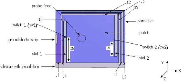
The geometry of the proposed antenna is shown in Fig. 1. The
newly manipulated patch antenna consists of a conventional patch antenna having the following optimal specifications and dimensions as reported in the literatures with little change in the feed location and substrate thickness [20]. The center frequency is 2.4 GHz, the ground plane dimensions are 50.95×59 mm2, the patch dimensions are 41.35 ×49.41 mm2. The dielectric substrate between the patch and the ground plane is of RT/ Duroid 5880 with relative permittivity
εr = 2.2 and thickness of 1.6 mm. The εr is chosen such that it gives better efficiency and larger bandwidth [21]. The antenna is fed by a coaxial probe feed of radius 3 mm. In order to increase the number of resonance frequencies and to enhance the bandwidth and gain of the conventional microstrip antenna a multi-band parasitic resonator elements are inserted into the antenna [13]. To tune the resonant
frequencies of the parasitic resonantors, two slots are added to the patch. Moreover, switches are integrated into the slots where the current paths become shorter and hence the operating frequencies increase [20]. The specifications of the proposed antenna are present in Table 1. The positions and dimensions of the parasitic, slots and switches are optimally chosen to give as many resonant frequencies as possible.
Table 1. Specifications of the proposed antenna.
Elements Dimensions (mm)
Ground plane 50.95x59(LxW).
Patch 41.35x49.41(LxW).
Patch thickness 0.07
Substrate thickness 1.6
Feed point location Xf = - 6.35, Yf = 0.0, the center of the antenna is at (0,0).
Probe feed radius 3.
Parasitic L1=4 mm, L2=L3=1.
Ground shorted strip 1x8(LxW). The slot between the parasitic arms 1.3
Widths of the slots around the patch S1=0.8, S2=1.495, S3=1.5
Slots(Slot 1 & Slot 2) 43x2(LxW) at distances L4=L5=1mm from S1 and S3.
Switches(SW1 & SW2) 1x2(LxW) at 26mm from the open edge of the slots.
3. SIMULATION AND RESULTS
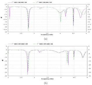
The proposed antenna is simulated using Zeland software’s IE3D simulation package [19]. For an initial design the optimum feed point is found to be at (Xf, Yf) = (−6.35,0) at which the return loss (RL) is −52.9339 dB at frequency 2.3975 GHz which is very closed to the desired operating frequency 2.4 GHz. Figure 2 shows the computed results of the RL as a function of frequency for the conventional antenna as well as for the conventional antenna with the parasitic elements. The results illustrated that when the parasitic resonator elements are enclosed to the patch more resonant frequencies are obtained with RL less than −9.54 dB in the range of 2–5 GHz. The number of the resonant frequencies can be increased using two slots with two switchessw1 and sw2 inserted into the patch. We optimally choose the positions of these two switches. The resonant frequencies depend on the states of the two switches. The computed results of the RL as a function of frequency are shown in Figs. 3(a) and 3(b) for different stares of sw1 and sw2 either on or off. The state at which
Figure 2. Return loss as a function of frequency for the conventional antenna and the conventional antenna with the parasitic.
(a)
(b)
(a) (b)
(c) (d)
(e)
Figure 4. Radiation pattern of E-fields in the ϕ= 0◦ and ϕ = 90◦ planes at different resonant frequencies, (a) fr = 2.0675 GHz, (b)
fr = 2.7875 GHz, (c) fr = 4.2050 GHz, (d) fr = 4.5125 GHz, (e)
(a)
(b)
Figure 5. Behaviors of the gain (a) and directivity (b) of the proposed antenna as a function of frequency.
switches for the multi-wideband operation. Five resonant frequencies in the frequency range with RL less than−9.54 dB are obtained. The variation of VSWR with frequency shows that it is≤2 at the resonant frequency bands corresponding to a RL less than−9.54 dB.
Figure 4 shows the radiation patterns of the|E|-field in theϕ= 0
and ϕ = 90 planes for the proposed antenna at different resonant
frequencies. Wide variations of the radiation pattern are obtained. The results show that the radiated power in the back loops is small compared to the forward radiated power at the frequencies 2.7875,
4.205, and 4.7825 GHz. The advantage of reducing radiation from
Figure 6. Behaviors of the antenna and radiation efficiencies of the proposed antenna with frequency.
the proposed antenna has a high gain and directivity. Its radiation efficiency is higher than 90% over the operated frequency range. Moreover the proposed antenna provides an enhancement of multi-wideband operation. Those advantages of the antenna benefit different applications.
4. CONCLUSION
A new reconfigurable compact microstrip antenna of operating frequencies in the range of 2–5 GHz with return loss less than−9.54 dB
is presented. Two switches are integrated into the slots of the
conventional rectangular patch antenna with parasitic and slots in
order to enhance and control the frequency bands. It has been
illustrated that the behavior of the return loss in the frequency range 2–5 GHz is better at a certain state of the two switches. The suggested design gives more resonant frequency bands with reasonable frequency bandwidths compared with the conventional antenna in the literatures. The positions and dimensions of the parasitic, slots and switches of the newly multi-wideband patch antenna are optimally chosen to give as many wide resonant frequencies as possible.
REFERENCES
1. Garg, R., P. Bhatia, I. Bahl, and A. Ittipiboon, Microstrip
Antenna Design Handbook, Artech House, Inc. 2001.
3. Balanies, C. A.,Antenna Theory: Analysis & Design, 2nd edition, John Wiley & Sons, Inc., 1997.
4. Singhal, P. K., B. Dhaniram, and S. Bannerjee, “A stacked square patch slotted broadband microstrip antenna,” Journal of
Microwaves and Optoelectronics, Vol. 3, No. 2, 60–66, August
2003.
5. Abbaspour, M. and H. R. Hassani, “Wideband star-shaped microstrip patch antenna,”Progress In Electromagnetics Research
Letters, Vol. 1, 61–68, 2008.
6. Kuo, J. S. and K. L. Wong, “A compact microstrip antenna with meandering slots in the ground plane,” Microwave & Opt. Tech.
Letter, Vol. 29, 95–97, April 20, 2001.
7. Eldek, A. A., A. Z. Elsherbeni, and C. E. Smith, “Characteristics of BOW-TIE slot antenna with tapered tuning stubs for wideband operation,”Progress In Electromagnetics Research, PIER 49, 53– 69, 2004.
8. Ang, B. K. and B. K. Chung, “A wideband microstrip patch
antenna for 5–6 GHz wireless communication,” Progress In
Electromagnetics Research, PIER 75, 397–407, 2007.
9. Waterhouse, R. B., “Broadband stacked shorted patch,”
Electronic Letters, Vol. 35, 98–100, January 21, 1999.
10. Ge,Y., K. P. Esselle, and T. S. Bird, “A broadband E-shaped patch antenna with a microstrip compatible feed,”Microwave &
Opt. Tech. Letter, Vol. 42, No. 2, 111–112, July 20, 2004.
11. Wong, K. L. and Y. F. Lin, “Microstrip-line-fed compact broadband circular microstrip antenna with chip resistor loading,”
Microwave Opt. Techno. Lett., Vol. 17, 53–55, January 1998.
12. Gandara, T., R. Urban, L. Fregoli, and C. Peixeiro, “Planar inverted-F antennas integrated into small multi-standard hand-sets,” Automatika, Portugal, ATKAAF, Vol. 48, No. 1–2, 45–52, 2007.
13. Amari, H., “Penta band antenna based on slot matching,”Project
at Laird Technologies, KTH, France, March 2007.
14. Sheta, A. F., A. Mohra, and S. F. Mahmoud, “Multi-band operation of compact H-shaped microstrip patch antenna,”
Microwave Opt. Technol. Letter, Vol. 35, No. 5, 363–367,
December 2002.
15. Sheta, A. F., A. Mohra, and S. F. Mahmoud, “Modified compact H-shaped microstrip antenna for tuning multi-band operation,”
25th National Radio Science Conference (NRSC2008), Tanta
16. Chiou, T. and K. Wong, “Designs of compact microstrip antennas with a slotted ground plane,” IEEE Antennas Propagat. Symp., Vol. 2, 732–735, Boston, USA, July 7–13, 2001.
17. Ollikainen, J., O. Kiveks, A. Toropainen, and P. Vainikainen, “In-ternal dual band patch antenna for mobile phones,” Proceedings
of the AP 200, Millennium Conference on Antennas Propagat.,
Davos, Switzerland, April 9–14, 2000.
18. Polivka, M., M. Drahovzal, J. Rohan, and P. Hazdra, “Multiband patch antenna with perturbation elements generated by genetic algorithm,” Proceedings of the “Eu CAP 2006”, Nice, France, November 6–10, 2006 (ESA SP-626, October 2006).
19. IE3D Software Release 14 developed by Zeland Software, Inc., 2008.
20. Alayesh, M. A., “Analysis and design of reconfigurable multi-band stacked microstrip patch antennas (MSAs) for wireless applications,” M.Sc. Thesis at University of New Mexico, Albuquerque, December 2007.